-
-
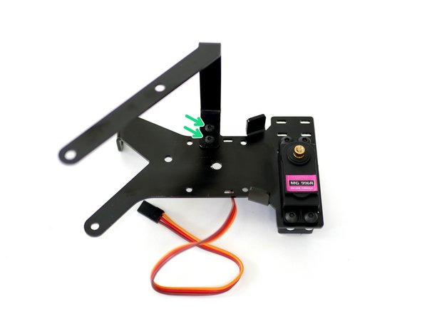
Begin by inserting the servo cable into the DSE (Dual Switching Extruder) Back Plate. The Cable should be on the left hand side.
-
Push the start of the cable up against the left edge of the back plate.
-
Push the other side until the bolts on the servo come through.
-
-
-
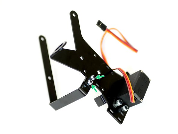
With the cables being pushed against the left edge of the DSE Back Plate firmly push on the right side of the DSE with your thumbs and firmly pull with your finders on the front of the servo to snap it through.
-
Fasten the servo to the DSE Back Plate with four M4 x 10mm bolts and M4 Nyloc Nuts.
-
-
-
Install the second print fan mount with two M3 x 8mm bolts and M3 Nyloc nuts.
-
-
-
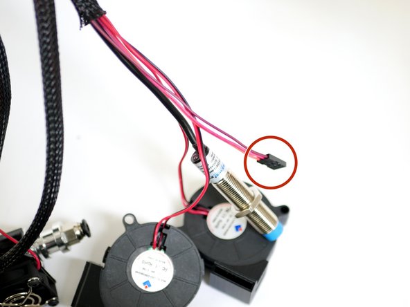
If you haven't already from stage 5 feed the servo cable into the braided cable sleeving with the probe and fans.
-
-
-
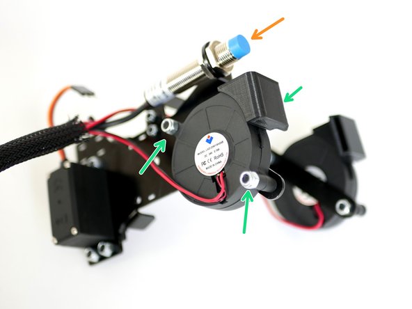
Install the print fan that has it's shroud facing inwards to the back of the DSE Back Plate.
-
M4 x 22mm and M4 Nyloc Nut
-
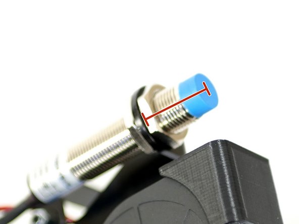
Mount the probe onto the DSE Back Plate.
-
The distance between the bottom of the mount and the bottom of the probe should be between 19-21mm if you have the Flexplate installed.
-
Without the Flexplate it should be between 21-23mm
-
-
-
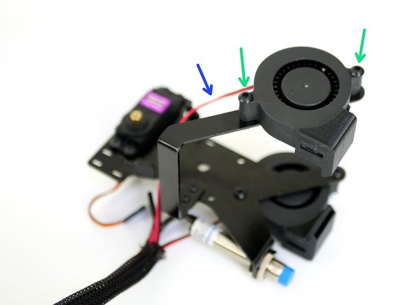
Install the second print fan onto it's mount with two M4 x 22mm bolts and M4 Nyloc Nuts.
-
Pull some of the fans cable out to be able to route it along the length of the mount.
-
-
-
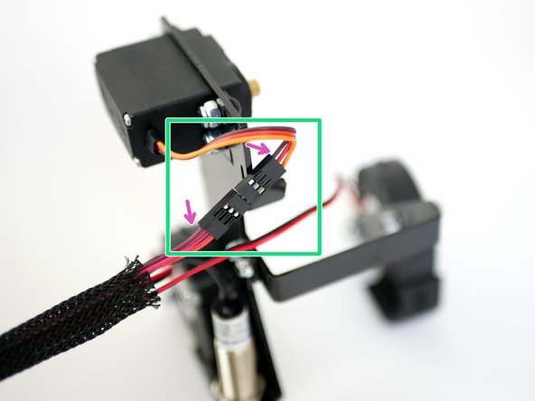
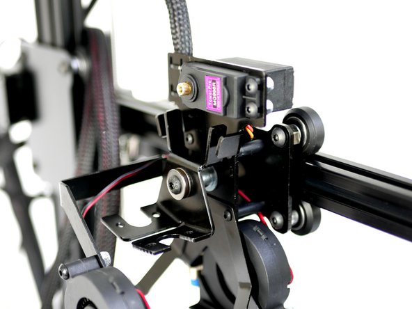
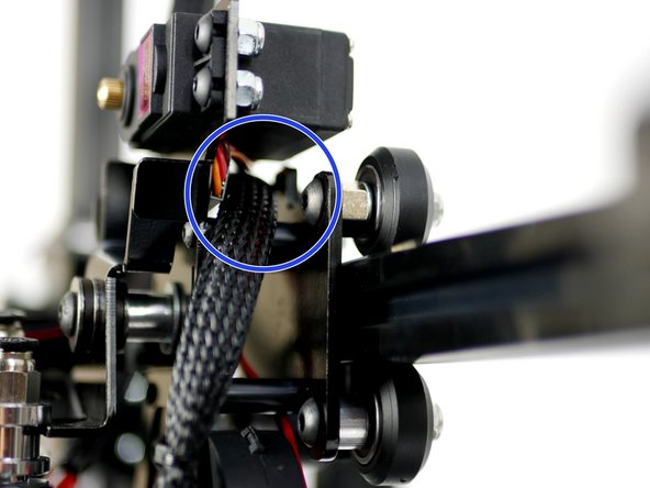
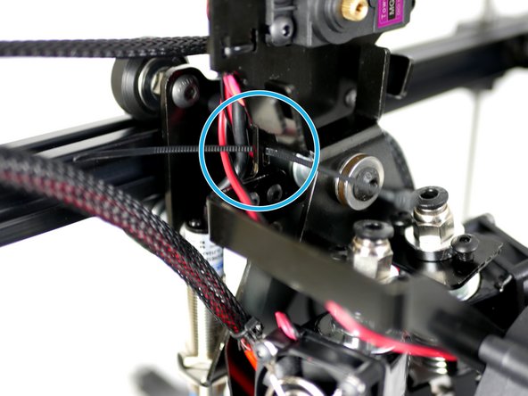
Connect the servo to the servo cable.
-
Brown to brown.
-
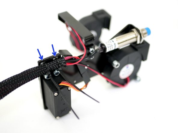
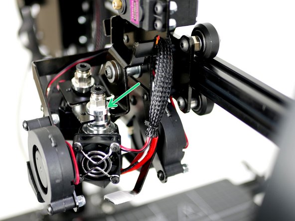
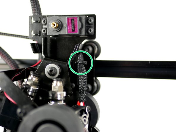
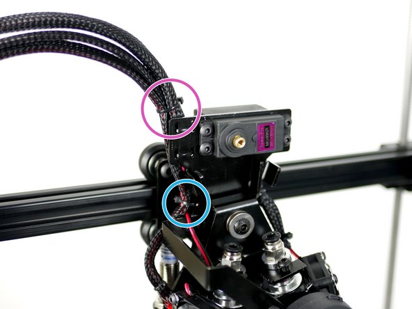
Cable tie the cables to the DSE Back Plate.
-
-
-
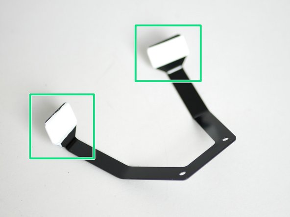
Wrap several layers of PTFE tape around both of the ooze shields like shown.
-
-
-
Prepare the DSE Back Plate:
-
M3 x 25mm Bolt
-
Ooze Shield
-
M3 x 20mm Spacer
-
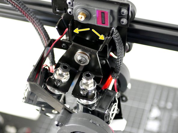
Carefully bring the DSE back plate up to the tool carriage and fasten the bolts into the mounting holes, starting with the bottom two first.
-
-
-
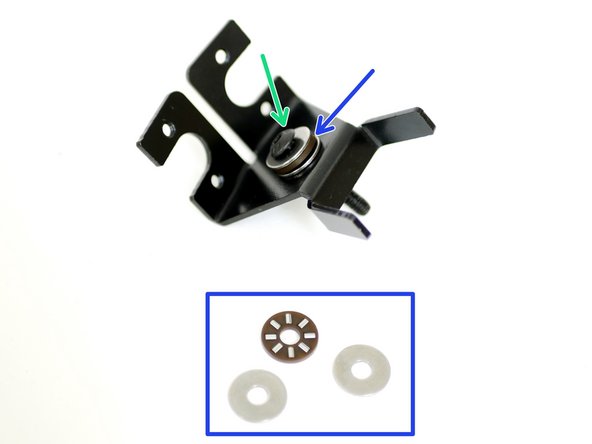
Prepare the DSE Hotend mount:
-
M5 x 30mm Bolt
-
Thrust Bearing Assembly
-
M5 x 9mm Spacer
-
M5 x 15mm Washer
-
-
-
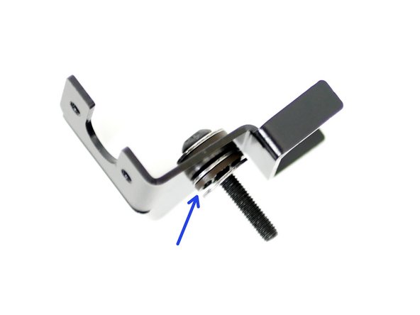
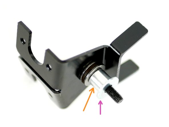
Fix the DSE Hotend Mount assembly onto the DSE Back Plate:
-
M5 x 15mm Washer
-
M5 x 30mm Bolt
-
Use the needle nose pliers to hold the M5 Nyloc Nut.
-
-
-
Follow the steps in Stage 4 to build the second Hotend.
-
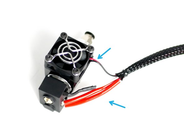
The second hotends cables should be on the right side.
-
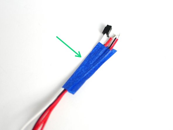
Use tape to mark the ends of the cables to distinguish between the two Hotends.
-
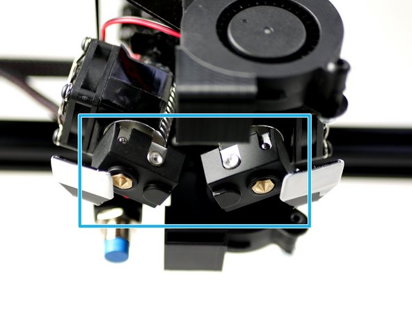
The Hotend with cables on the left side is Hotend #1
-
The Hotend with cables on the right side is Hotend #2
-
-
-
Place the Hotend #1 (cables on the left) onto the left side of the DSE Hotend Mount.
-
Place Hotend #2 (cables on the right) onto the right side of the DSE Hotend Mount.
-
Slide Hotent #2's cables in between the DSE Back Plate and the Tool Carriage.
-
-
-
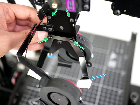
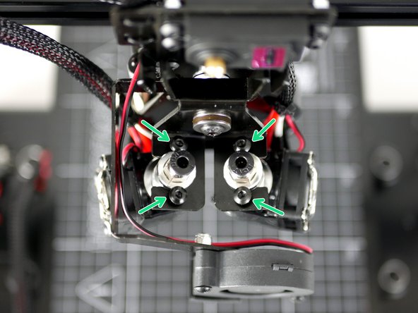
Fix the Hotends onto the mount with four M4 x 8mm Bolt.
-
Angle the bottom of the hotends as shown shown.
-
The DSE Hotend Mount should be able to swivel easily without any bumps or restrictions.
-
-
-
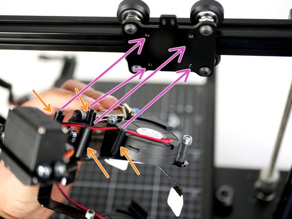
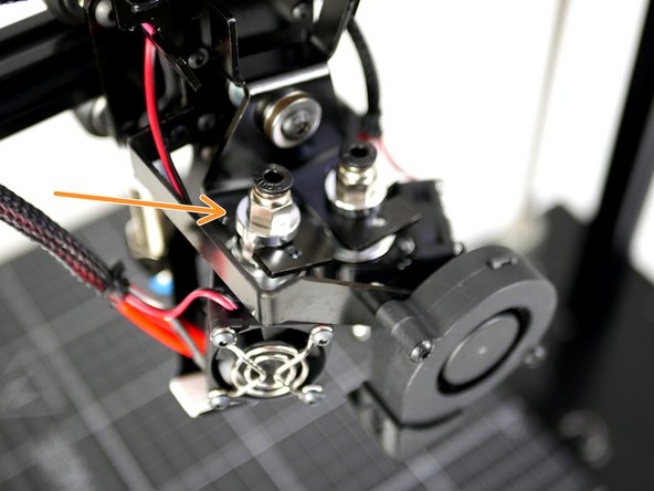
Cable tie Hotend #2's cables to the DSE Back Plate.
-
Cable tie Hotend #1's cables to the DSE Back Plate.
-
Cable tie all of the cables at the top of the DSE Back Plate.
-