
-
-
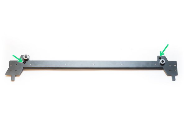
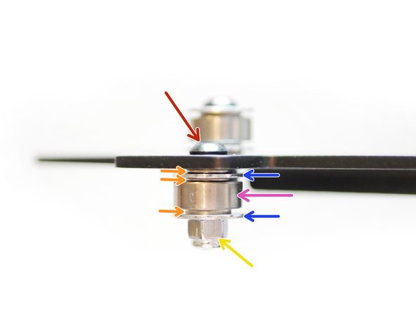
Build the Idler assembly onto the gantry panel as shown.
-
M4 x 30mm
-
M4 Penny Washer
-
M4 Washer
-
624zz Bearing
-
M4 Nyloc Nut
-
The longer bolt is used here, as it also acts as an end stop trigger for the x-axis.
-
Note the orientation of the aluminium gantry beam, double-check the Idler is installed in the correct position and on the correct side.
-
-
-
On the other side of the gantry beam build the remaining top side Idler assembly.
-
M4 x 18mm Button
-
M4 Penny Washer
-
M4 Washer
-
624zz Bearing
-
M4 Nyloc
-
Note the orientation of the aluminium gantry beam, double-check the Idler is installed in the correct position and on the correct side.
-
-
-
Install the two bottom side idler assemblies as shown.
-
M4 x 18mm Button
-
M4 Penny Washer
-
M4 Washer
-
624zz Bearing
-
M4 Nyloc Nut
-
Note the orientation of the aluminium gantry beam, double-check the Idler is installed in the correct position and on the correct side.
-
-
-
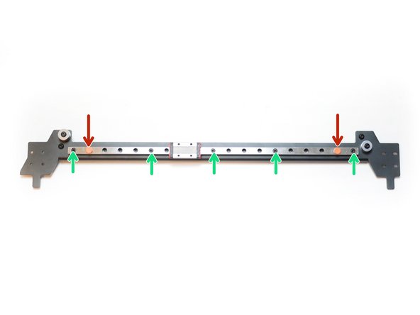
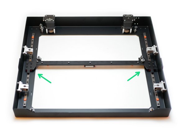
Remove the final rail from its packaging and move the red carriage stoppers inwards one hole space.
-
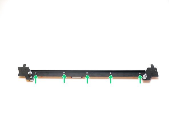
Secure the rail to the gantry as shown with five M3 x 10mm cap head bolts and M3 nyloc nuts.
-
If the aluminium gantry is slightly warped, do not worry; the rail, when secured to it, is designed to give it its structural strength.
That’s now been corrected, M3 x 10mm bolts should be used here.
-
-
-
If you are building the 3.5 upgrade, skip this step.
-
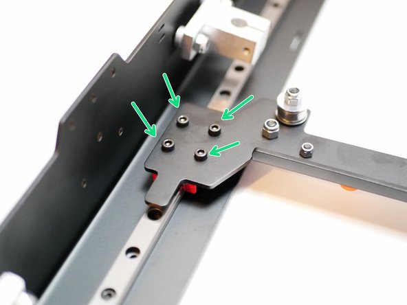
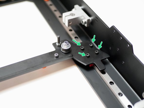
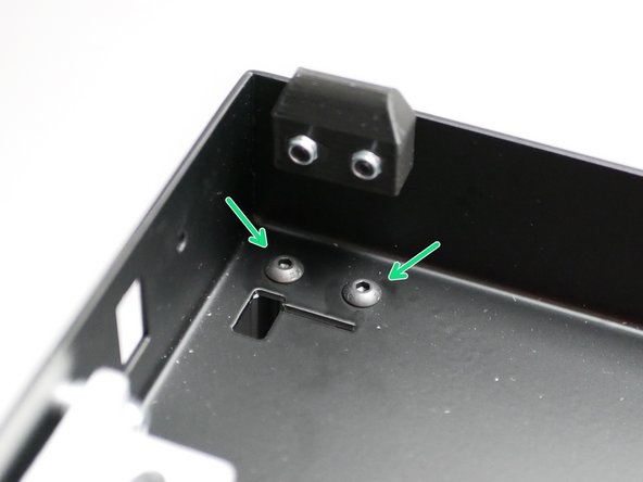
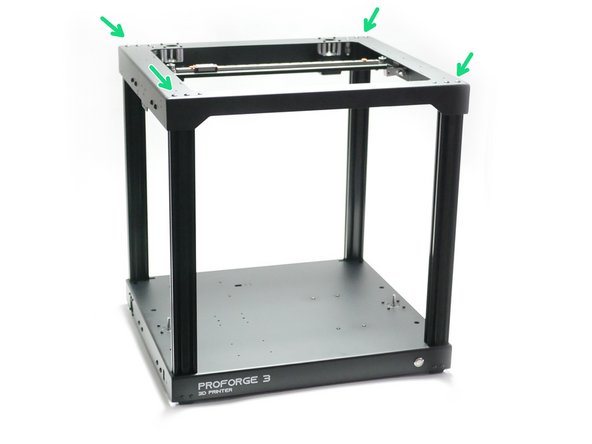
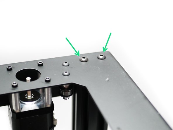
Secure the gantry to the top panel as shown. Note the orientation of the gantry assembly.
-
The gantry fixes onto the carriages of the y-axis rails.
-
M3 x 6mm Cap
-
Secure each bolt lightly to begin with, tighten firmly when all bolts are in place.
Is there a better, more surefire way to make sure this is properly aligned (or does this come later)?
The tension from the belts will align the gantry, you do not need to worry about it at this stage.
-
-
-
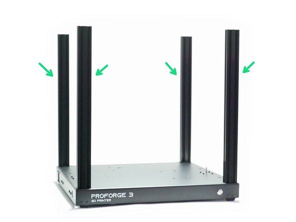
Secure the four 2040 aluminium extrusions to the base.
-
M5 x 6mm Button
I de-burred the threaded holes that the profile sits flat on mating part. Also M5x6 seems a little weak. I propose to use M5x10mm to improve strength
Great suggestion! I used 10mm in place and it feels much better!
Peter -
Why was the legs not offset from the extrusion screw holes? My kit did not include the M5 allen key,
-
-
-
If you are building v3.5 continue this stage from here.
-
Secure the top panel assembly onto the 2040 extrusions.
-
M5 x 6mm Button
-
-
-
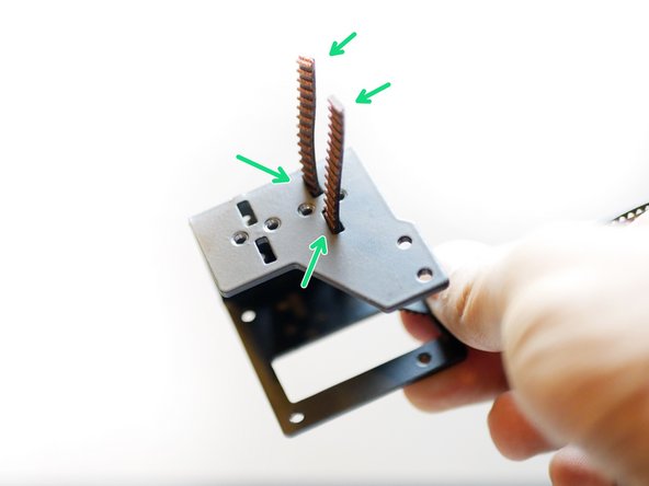
Take the 4M roll of GT2 belt and cut it in half.
-
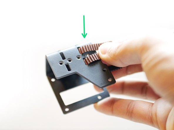
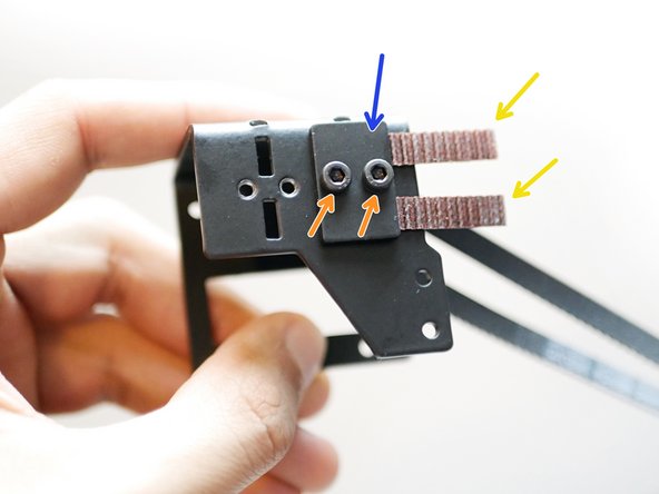
Feed one side of each of the two lengths into the back of the tool carriage as shown.
-
Secure in place with one of the belt clamps.
-
M3 x 6mm Cap
-
Leave approximately a CM of extra length. Make sure that the belts are clamped down straight and horizontal.
-
-
-
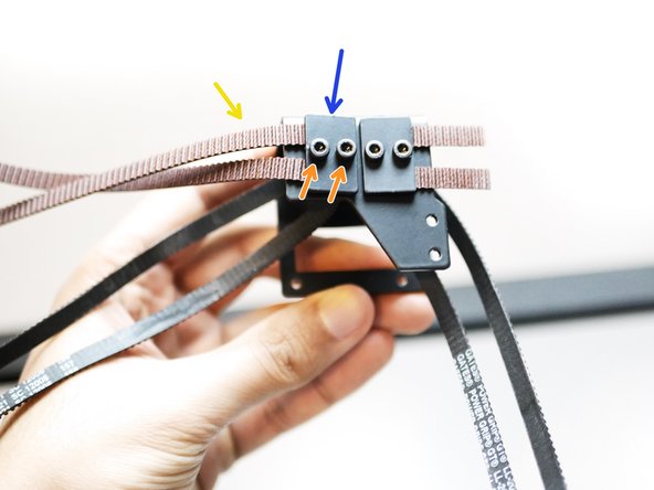
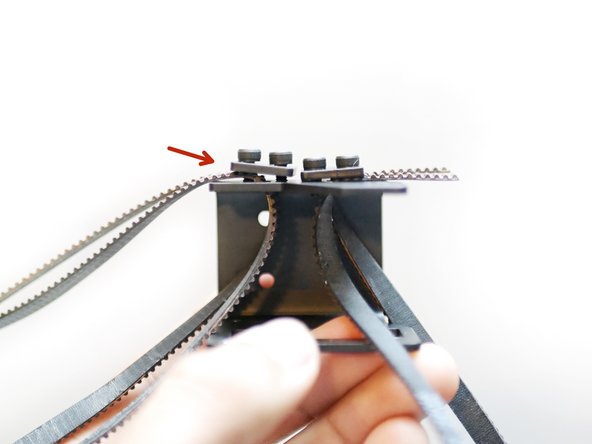
Loop the lengths of belt around, making sure to keep them from getting twisted. The inside of the loop should be the toothed side of the belt. Feed the other end into the corresponding slot on the other side of the tool carriage.
-
Use the remaining belt clamp to hold the belt in place.
-
M3 x 6mm Cap
-
Do not tighten this clamp down fully, but just enough to hold the belt in place. You should still be able to pull and push the belt through the slot.
-
Leave about a few inches free.
So to me, it looks like the inside of the loop should be the tooth'd side… not the smooth side. Am I misunderstanding something here?
Updated now :)
Yes. Teeth inward for the whole loop. This instruction should be updated.
Peter -
-
-
-
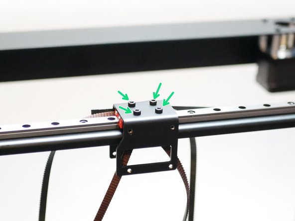
Mount the tool carriage to the gantry as shown. Note the belt claps are facing the rear of the printer, towards the motors.
-
M3 x 6mm Cap
-
-
-
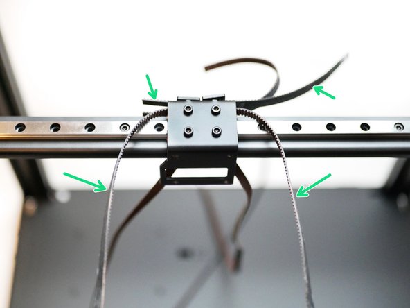
Take the upper belt loop and swing it over the front of the gantry.
-
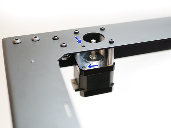
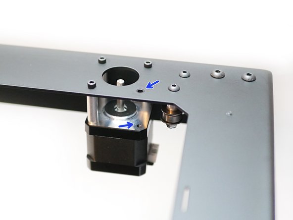
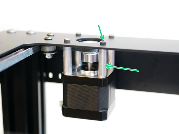
Remove these two bolts and spacers on the motors as shown.
-
-
-
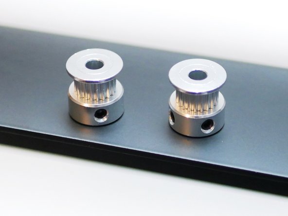
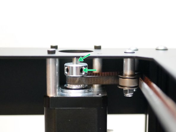
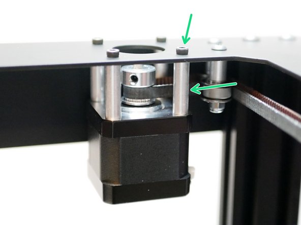
Drop a pulley onto each of the motor shafts.
-
Note, the pulley's orientation for each motor.
-
Left motor pulley
-
Right motor pulley
Do we need to add threadlocker to the grubnuts?
Also I had to change my name for the comment to post lol
If you have some, it wouldn’t hurt.
-
-
-
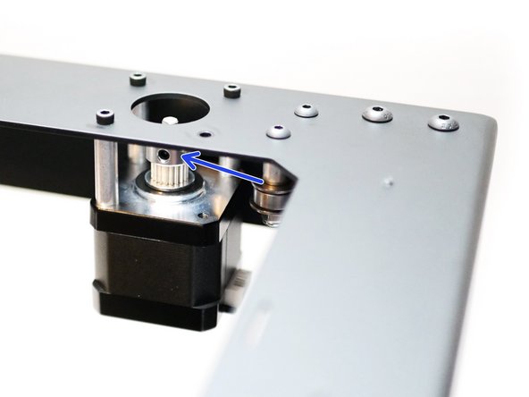
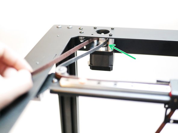
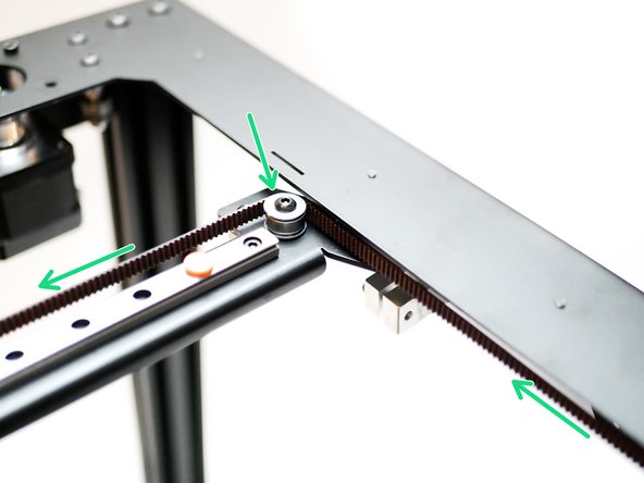
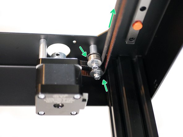
Take the upper belt and begin by wrapping the smooth side around the left idler on the gantry.
-
-
-
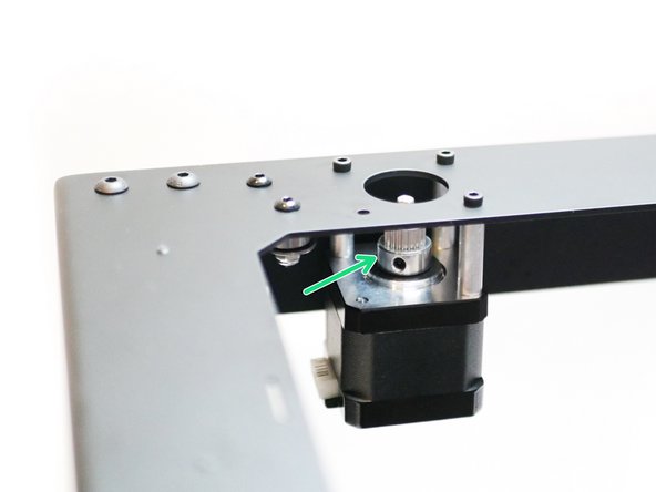
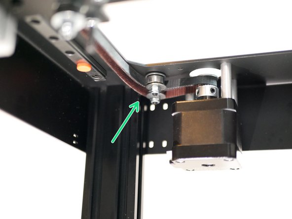
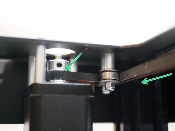
Next, wrap it around the left motor's pulley as shown.
-
The belt's teeth should grip the pulley.
-
-
-
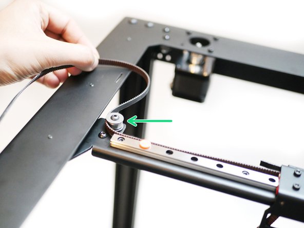
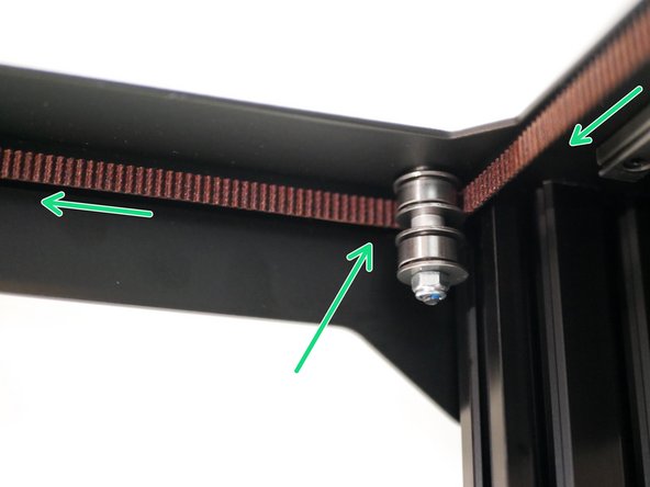
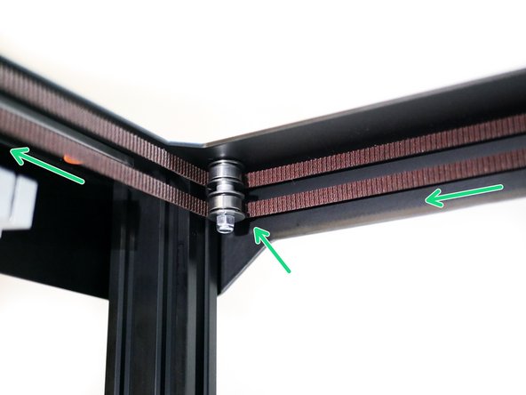
Whilst keeping some tension on the belt to prevent it from falling off the idlers, pull it forward and wrap it around the front idlers like shown.
-
-
-
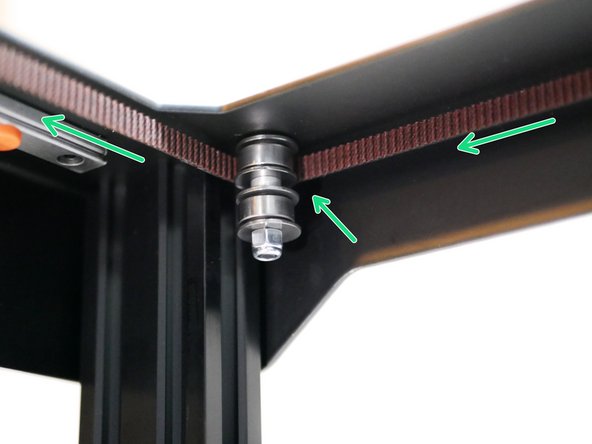
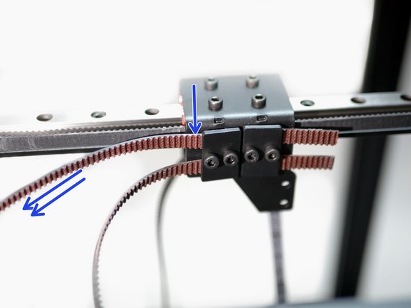
Finally, wrap it around the final idler on the gantry.
-
Pull the belt tight to hold it in place, but do not tighten the clamp down just yet.
-
-
-
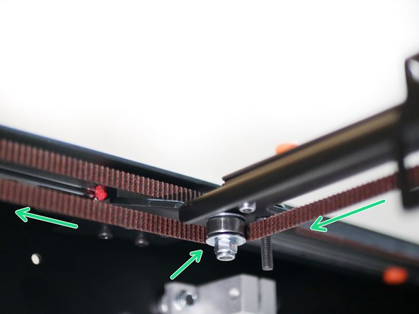
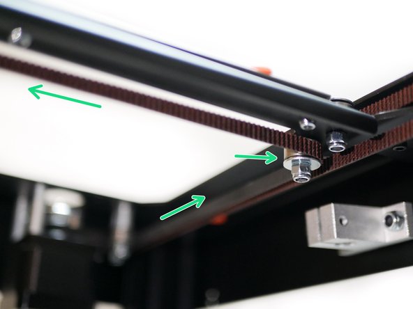
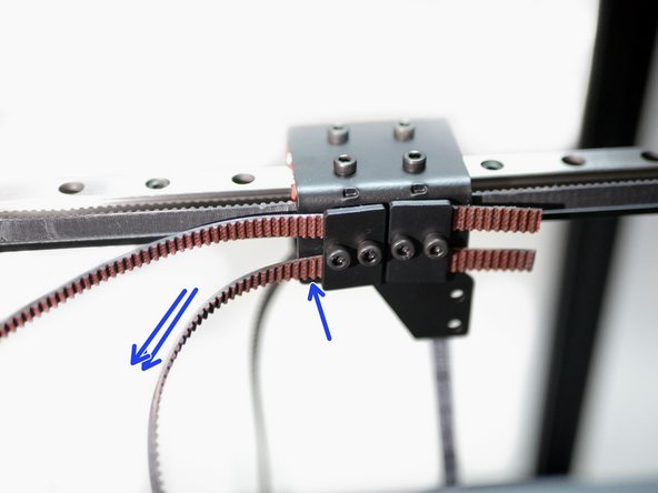
Take the left side of the belt and wrap it around the lower left idler on the gantry as shown.
-
-
-
As before, wrap the belt around the motor pulley first and then around the two rear right idlers like shown.
-
-
-
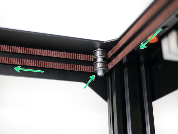
Finally, wrap the belt around the lower right idler on the gantry.
-
And, as before, pull the belt tight on the tool carriage.
-
-
-
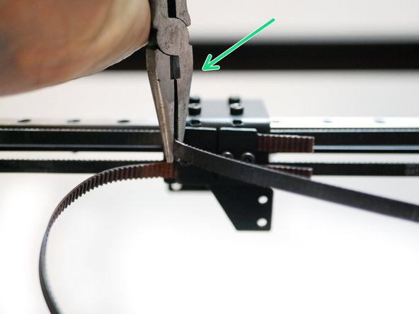
Use a pair of needle nozzle pliers (included) to tighten the belts.
-
Grip the belts with the pliers and twist against the carriage to tighten.
-
Before starting, make sure that the clamp is tightened down enough to allow you to pull more belt through, but not allow the belt to slip back.
-
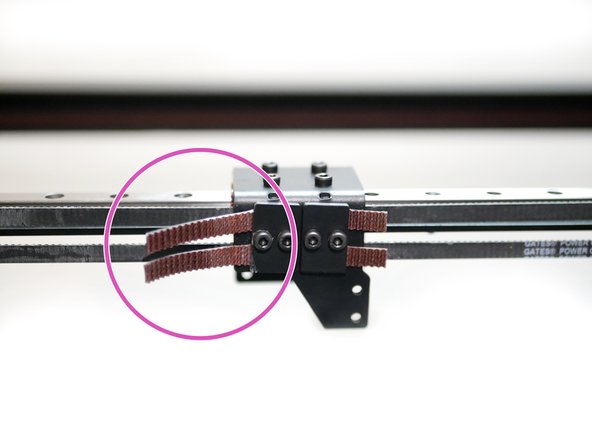
As a rule of thumb, the belts should be guitar string tight. However be cautious not to over tighten as that could cause the idlers to twist.
-
Trim away excess belt leaving approx an inch dangling.
It’s worthwhile to double check your belts are around all of the idlers before aggressively trimming the belts. It’s easier to continue to trim than to find out you’ve cut and inch too far because you’re ordering more belt or cannibalizing from another project at that point.
-
-
-
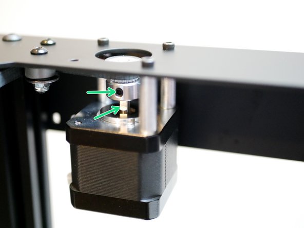
Move the tool carriage around by hand to set the pulley's to the correct heights.
-
Align the flats of the motor's shaft's to the pulley's grub screws and firmly secure the pulley's in place.
-


Cancel: I did not complete this guide.
6 other people completed this guide.

3 Comments
Note that you have to remove the orange rail bumpers once you’ve got everything securely in place - otherwise the x/y end stop triggers are way out of reach.
The lower belt keep on jumping when the carriage is moved.
I will be replacing the besting/washers assemblies with proper flanged idlers. Any reasons mot too ? Or changes to apply ?
I have the same issue - the washers seem slightly too small to properly guide the belt. Replacing with flanged bearings seems like a good idea, although bigger washers may do the trick as well.