
-
-
Feed the motor cables through the slots in the base.
-
Use electrical tape to hold the cables onto the extrusions.
-
-
-
Connect the X/Y motors to the control board as shown.
-
The left motor connects to the Y position on the board.
-
The right motor connects to the X position on the board.
-
-
-
Take the expansion board out of its packaging.
-
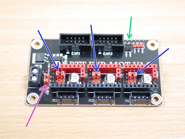
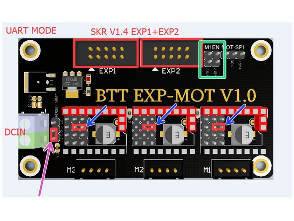
Remove the two jumpers from here.
-
Arrange these jumpers as shown.
-
Ensure that this jumper is set to 3V.
-
-
-
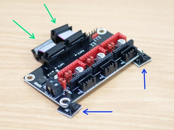
Connect the ribbon cables to the expansion board.
-
Use cable ties to fix the cable tie mounts to the mounting holes as shown.
-
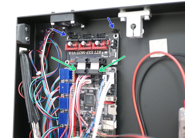
Connect the expansion board to the main board.
-
Fix the cable tie mounts to the base.
-
-
-
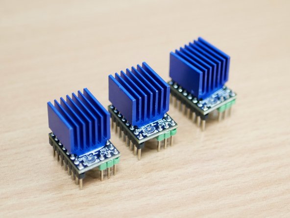
Unpack the three TMC2209 drivers and add to them the heatsinks.
-
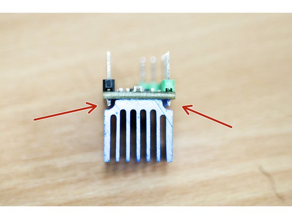
Ensure the heatsink is not touching any of the pins.
-
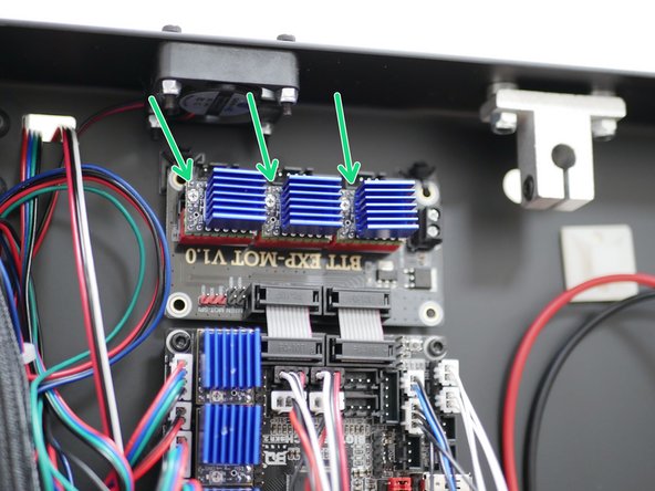
Plug the drivers into the expansion board as shown.
-
Make sure that the trimpots are pointing towards the rear of the printer as shown.
-
-
-
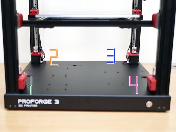
The Motors are numbered 1 - 4. Starting with the one in the near left side corner and working clockwise.
-
Cables - Two are from the original Z-motors, that are connected to the control board. The other two are from the top panel motors.
-
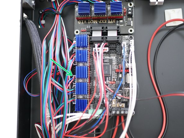
Motor 1 connects to the main board.
-
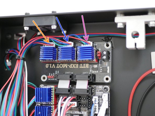
The remaining three are connected to the expansion board.
-
Motor 2
-
Motor 3
-
Motor 4
-
-
-
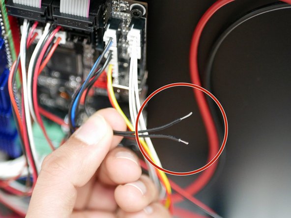
Take the central wire from the servo extension cable and make a cut a few inches from the connector.
-
Expose the wire.
-
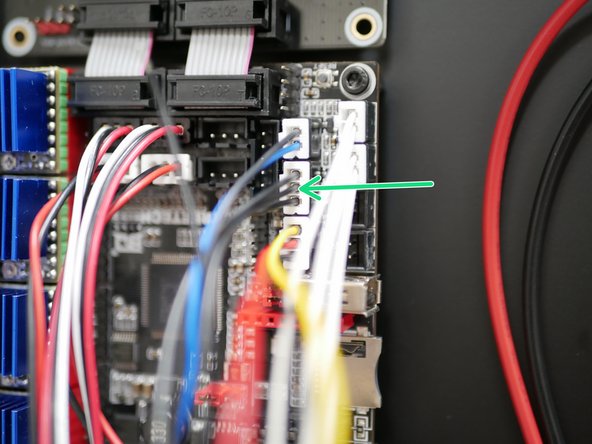
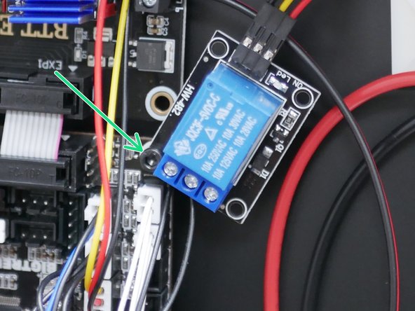
Connect the exposed wire to the relay switch as shown.
-
Connector Side
-
Servo Side
-
-
-
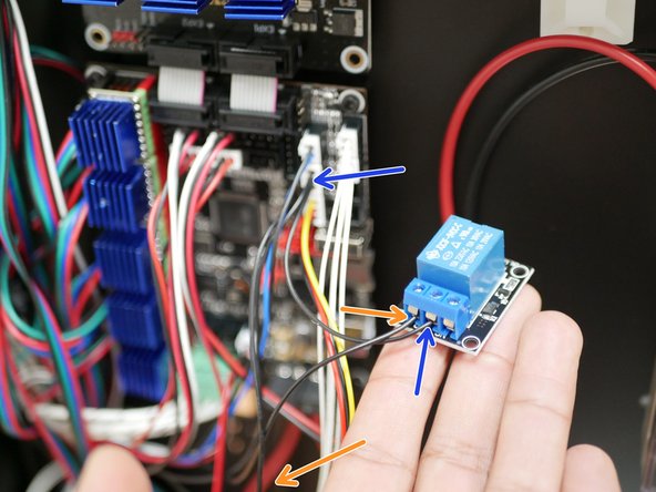
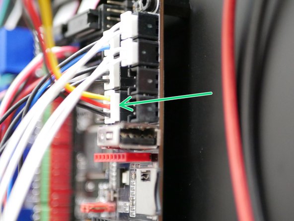
Plug into the control board the three colour cable.
-
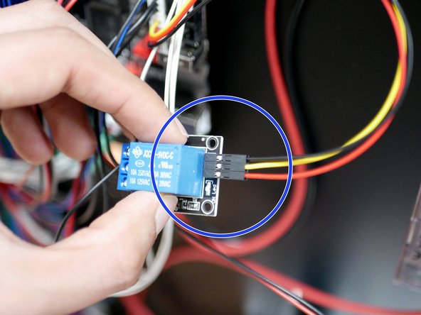
Connect the single connector sides of the cable to the relay switch in the order shown.
-
-
-
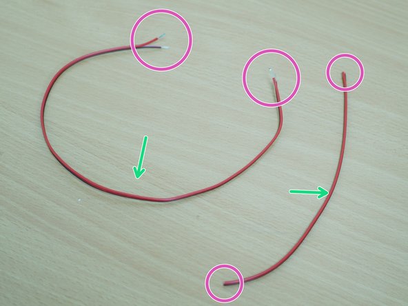
Take the 60CM cable and cut it into 40CM and 20CM lengths.
-
Strip the ends of both. (The smaller cables ends are not stripped in the image, but need to be also).
-
-
-
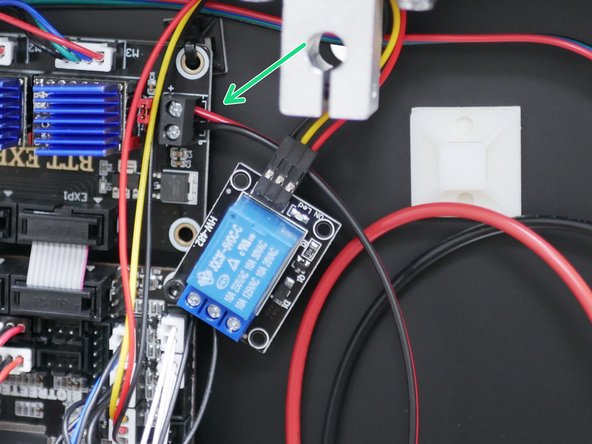
Take the longer 40CM cable.
-
Connect it to the terminal on the expansion board, with red to positive and black to negative.
-
-
-
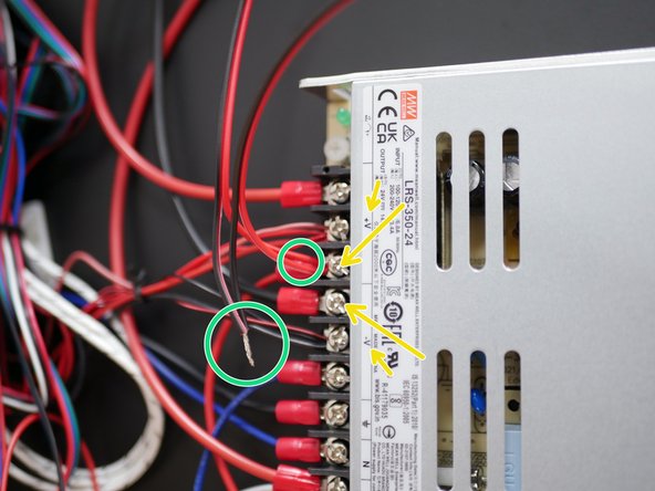
Take the other end of the cable and wind it together with the exposed end of the shorter (20CM) power cable.
-
Black to black, and red to red.
-
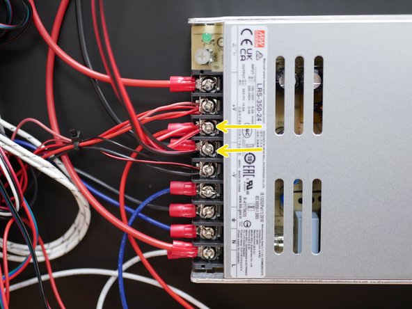
Fix the cables to the terminals on the power supply. Red to positive and black to negative.
-
-
-
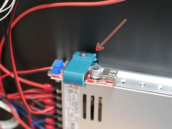
If you have the old converter installed, you can discard it and its mount.
-
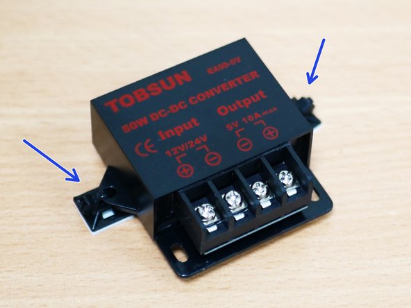
Take the new converter and add to it two cable tie mounting pads.
-
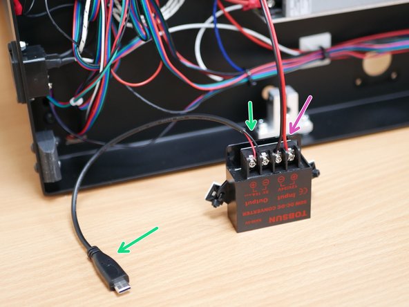
Connect to its terminals:
-
USB Power Cable
-
Short length (20CM) power cables
-
Ensure that red goes to positive and black to negative.
-
-
-
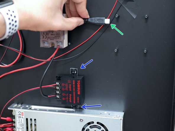
Fix the 5V converter to the base with the cable tie mounting pads.
-
Ensure that the USB cable can reach where the Pi board would be mounted as shown.
-
-
-
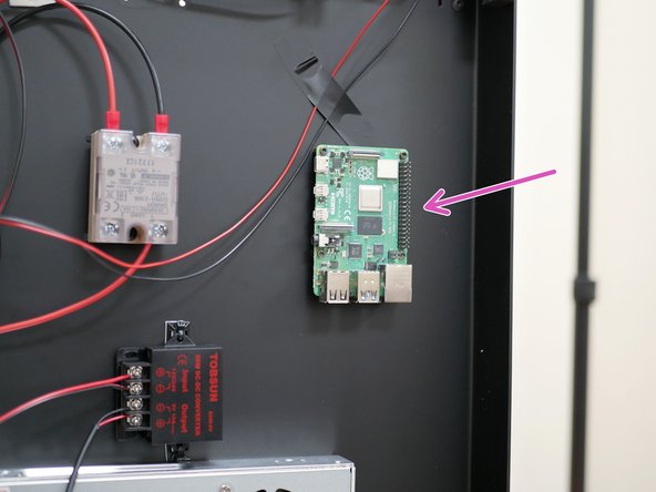
Mount the Raspberry Pi board to the base.
-
A Raspberry Pi 4 (1GB Ram minimum) is recommended. Due to stock shortage we were not able to supply one with the upgrade. You will have to source this part locally. A raspberry Pi 3B+ is also compatible.
-
Mounting requires 8x M2.5x6mm bolts and 4x M2.5 threaded spacers. Due to an oversight these were not included in the upgrade kit, if you don't already have these from the original printer's Octopi upgrade use cable tie mounts instead.
-
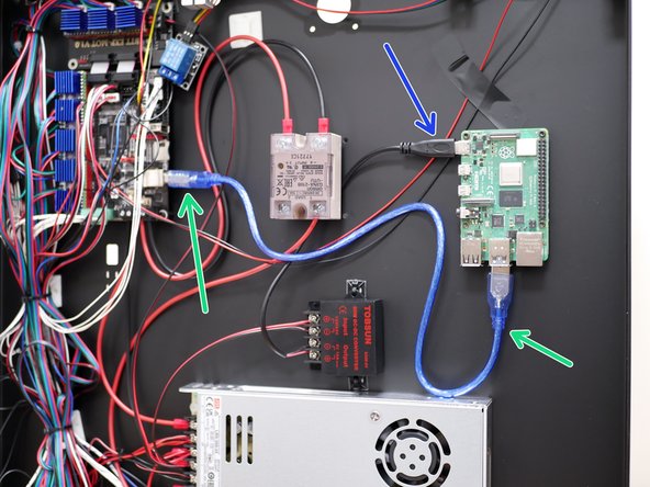
Connect the USB power cable to the Raspberry Pi.
-
Connect the control board data cable to the USB port on the Raspberry Pi. You should already have this cable, it was included with the main control board. If not, it is a standard USB type B printer cable.
-


Cancel: I did not complete this guide.
3 other people completed this guide.
