
-
-
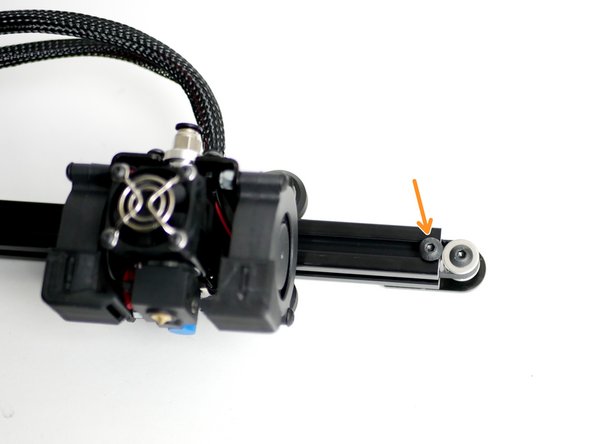
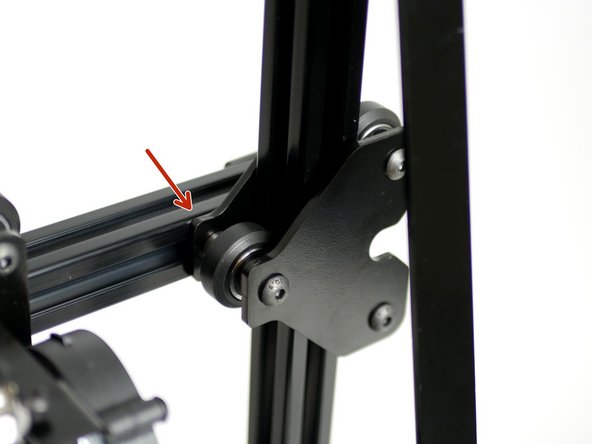
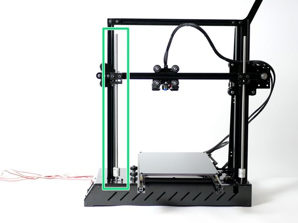
Slide the Z-Axis Carriage of the Gantry onto the 2040 beam of the frame.
-
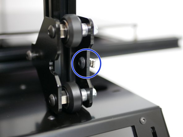
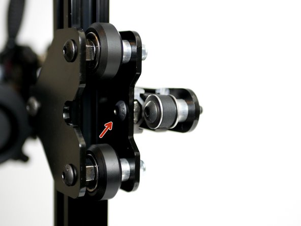
Adjust the eccentric spacers to remove any wobble between the rollers and grooves in the beam. Tighten the M5 nyloc nuts to secure.
-
-
-
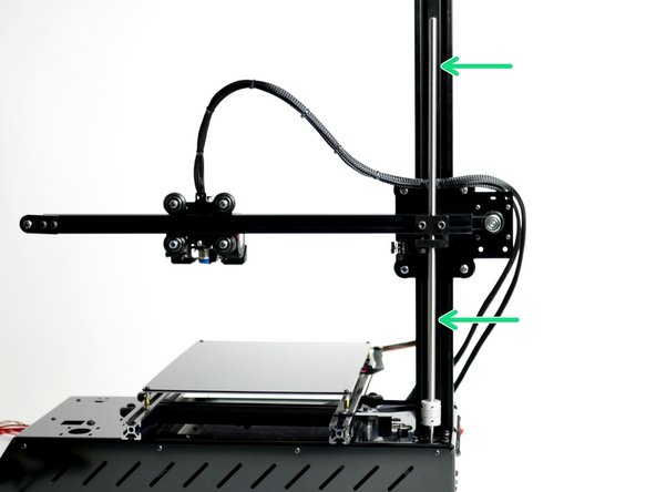
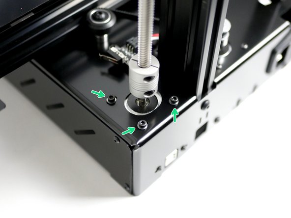
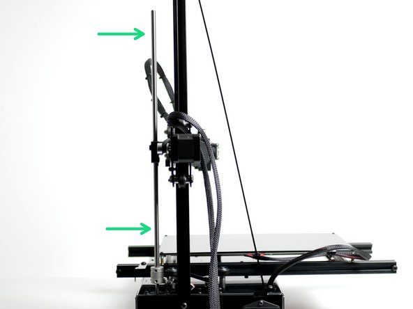
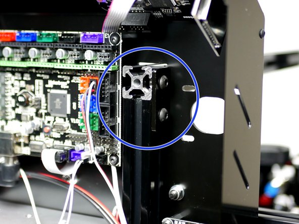
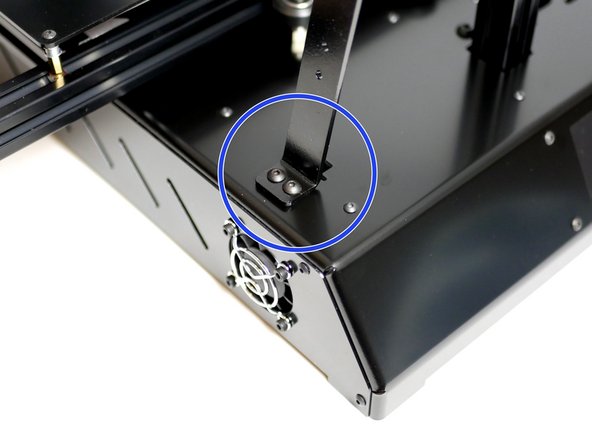
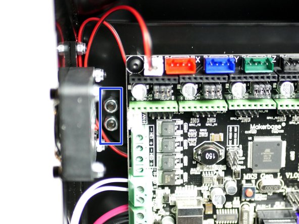
Fix the bottom of the support beam to the Base:
-
Two M4 x 10mm Bolts
-
Two M4 Nyloc Nuts
-
You may need to temporarily remove the IEC switch to get better access to the nyloc nuts.
-
-
-
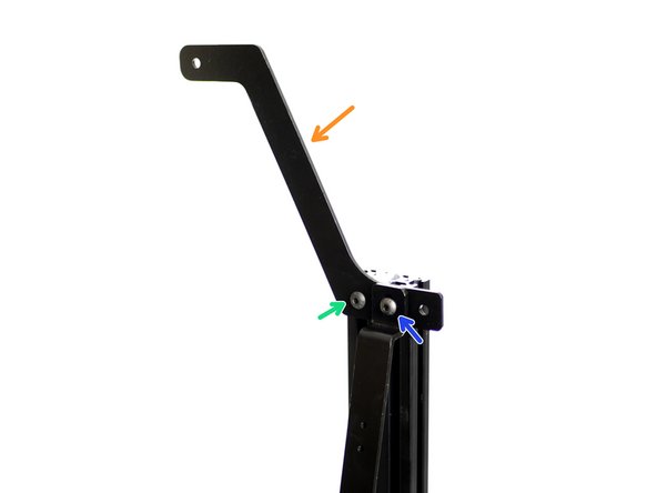
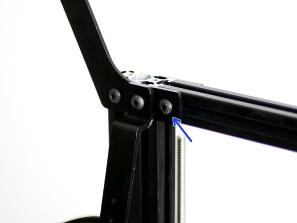
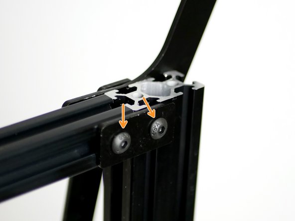
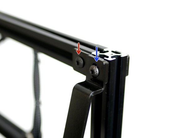
Fix the top of the support beam to the top of the 2040 beam with the spool holder fixed in between.
-
Spool Holder
-
M5 x 8mm + T-Nut Assembly
-
M5 x 10mm + T-Nut Assembly
-
-
-
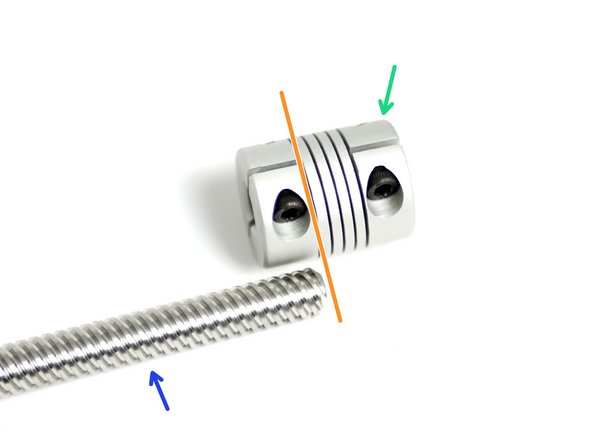
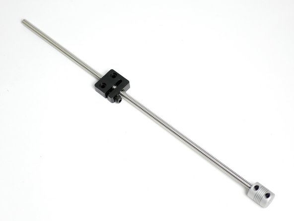
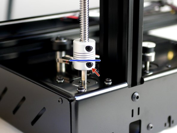
Assemble the Leadscrew to the Spring coupling.
-
Lead Screw
-
Spring Coupling
-
Push the lead screw up to the spring part of the coupling marked in the first image.
-
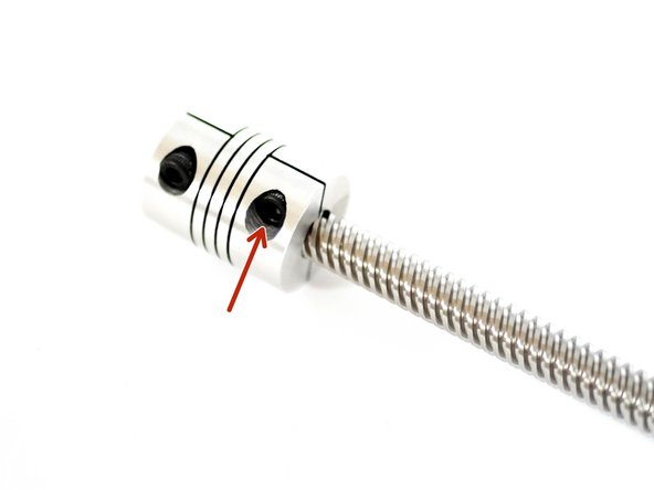
FIRMLY secure the bolt.
-
-
-
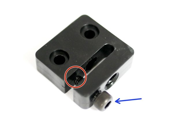
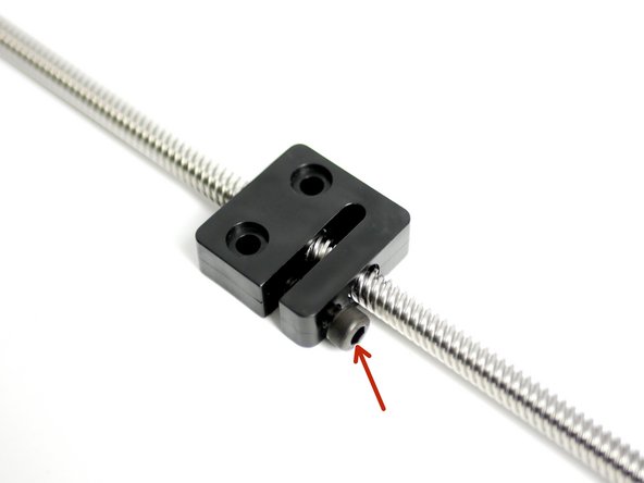
Prepare the Anti-Backlash Nut with an M5 x 14mm bolt.
-
Do not let the end of the bolt touch the nut yet.
-
-
-
Thread the Anti-Backlash Nut onto the Leadscrew with the bolt side facing towards the coupling.
-
SLOWLY tighten the M5 bolt on the nut to remove any wobble between the nut and leadscrew.
-
-
-
Push the Spring Coupling onto the shaft of the Z motor. Again clamping only up to the spring part of the coupling as marked on the first image.
-
Clamp it down FIRMLY.
-
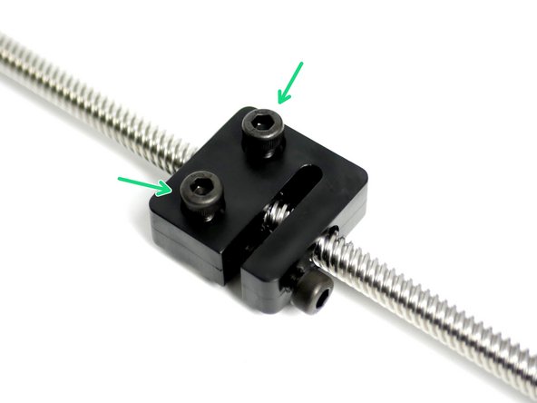
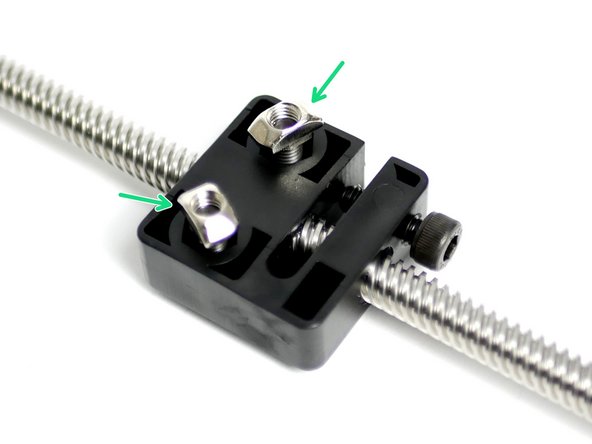
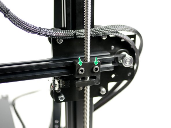
Fix the anti-backlash nut onto the gantry beam.
-
Adjust the position of the anti-backlash nut until your happy that when looking at it side on the lead screw is straight.
-
-
-
Loosen the bolts holding the z-Motor and adjust its position until the leadscrew is straight when looking at it from behind.
-
Tighten the motors bolts when happy with the position.
-
The alignment of the leadscrew doesn't have to be perfect, but the closer to being straight the better. The spring coupling will compensate for any imperfections.
-
-
-
All steps after and including this one are for the Proforge 2S assembly.
-
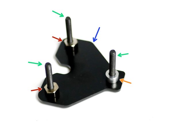
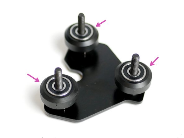
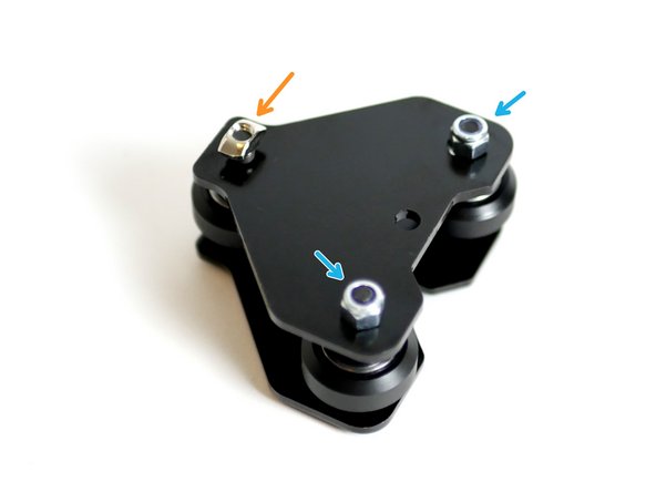
Install the rollers onto the the guided Y-Idler bracket:
-
Guided Y-Idler bracket
-
Lay flat matching the image.
-
Three M5 x 35mm Bolts
-
Four M5 Spacers. One against bracket, three on top of rollers
-
Two Eccentric Spacers
-
Roller Assembly
-
-
-
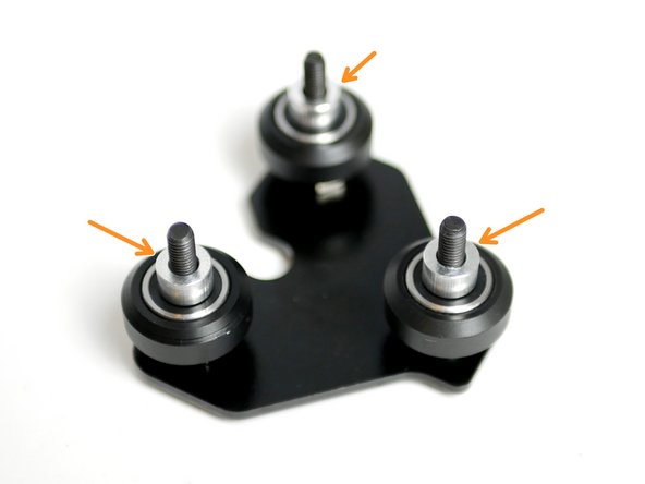
Complete the assembly by securing the guided Y-Idler support bracket:
-
Two M5 Nyloc Nuts
-
Tighten loosely so that the eccentric nut can still turn.
-
One M5 T-Nut
-
-
-
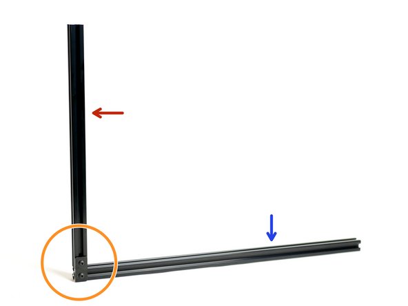
Secure together the two remaining aluminium beams:
-
With the 500mm beam laid flat and the 360mm beam on top of it vertically, the metal bracket should be fixed to the right hand side like shown in the image.
-
2020 x 500mm
-
2020 x 360mm
-
Extrusion Bracket
-
Two M5 x 8mm bolts and T-nut Assemblies
-
-
-
Slide onto the 500mm beam the guided Y-Idler assembly.
-
Insert the 500mm beam into the front of the Base.
-
Fix the end of the 360mm beam to the spool holder with an M5 x 8mm Bolt and M5 T-Nut.
-
Secure the other side with an extrusion bracket, two M5 x 8mm bolts and M5 T-Nuts.
-
-
-
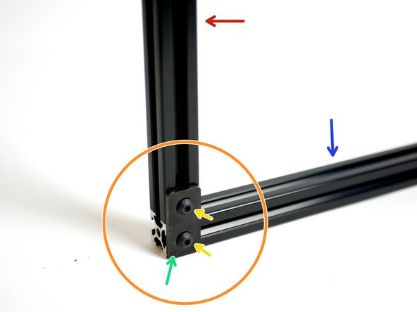
Fix an extrusion bracket with two M5 x 8mm bolts and M5 T-Nuts onto the bottom of the 2020x500mm beam connecting it to the 2020x360mm beam under the base.
-
Only one of the frame here will have an extrusion bracket fixed to it.
-
Make sure the bottom of the 500mm beam is level with the side of the 360mm one.
-
-
-
Fix the bottom of the support beam to the base with two M4 x 10mm bolts and M4 Nyloc Nuts.
-
-
-
Fix the Support Beam to the top of the frame with an extrusion bracket in between:
-
M5 x 8mm Bolt + M5 T-Nut
-
M5 x 10mm Bolt + M5 T-Nut
-
-
-
Remove the M5 x 8mm + M5 T-Nut from the end of the gantry beam.
-
Fix the M5 x 8mm + M5 T-Nut onto the Y-Idler guided assembly.
-
-
-
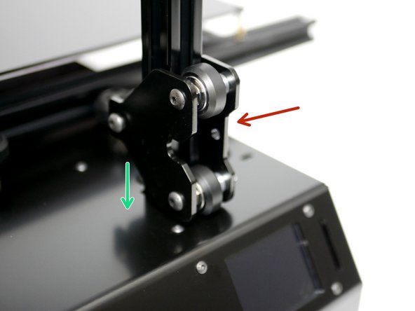
Fix the Guided Y-Idler Assembly onto the gantry beam.
-
The beam should be flush with the end of the idler assembly. Adjust the position of the Z-axis bracket onto the 2020 450mm beam if needed (Stage 3 Step 3).
-
Make final adjustment of Y-Axis belt tension.
-
Trim Y-Axis belt
-
-
-
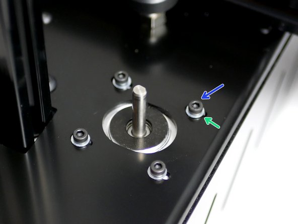
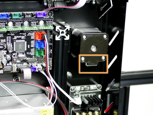
Fix a NEMA 17 Motor to the front of the base:
-
Four M3 x 6mm Cap Heap Bolts
-
Four M3 Washers
-
Match the cable connector orientation as shown in the second image.
-
-
-
To install the leadscrew repeat steps 4-9 of this stage.
-


Cancel: I did not complete this guide.
24 other people completed this guide.
