
-
-
Download the Marlin firmware depending on your configuration (updated 9 April 2022):
-
-
Unzip and copy the firmware.bin file to the micro SD card.
-
Insert the SD card into the control board.
-
-
-
Double check all of your wiring with the wiring diagram.
-
In particular, the wiring of the power supply and heated bed.
-
-
-
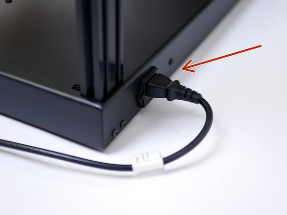
Plug the power cable into the back of the printer.
-
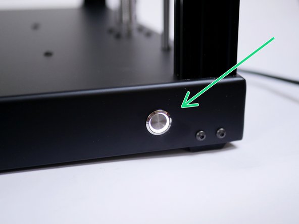
Power on with the switch on the front of the base.
-
If you find your power switch getting stuck 'ON', it is likely secured on too tightly. Loosen the nut holding it to the base.
-
-
-
Powering on for the first time should result in the following:
-
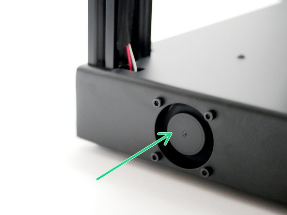
Electronics Fan should spin.
-
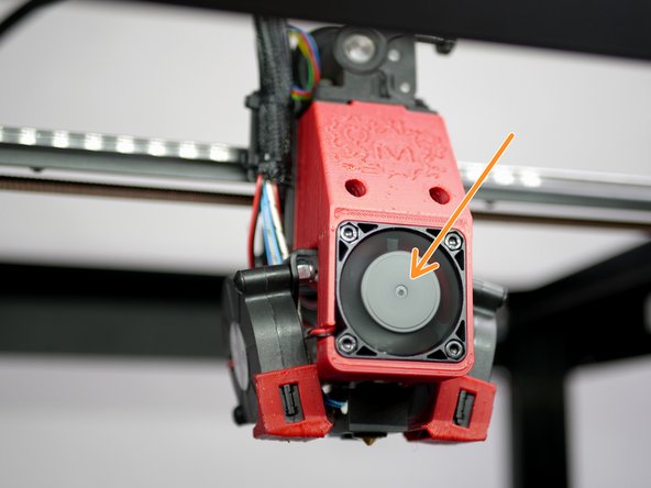
Hotend Cooling Fan should spin
-
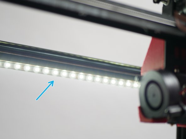
LED's should light up.
-
If after a 2-3 minutes you do not get your hotend fan spinning, power off, wait 10 seconds and power on again.
-
-
-
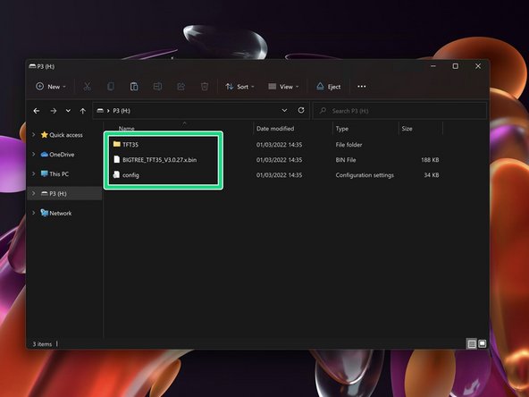
Download the display firmware for the Direct Drive set-up here.
-
Delete any files on the SD card and copy these files onto the SD card.
-
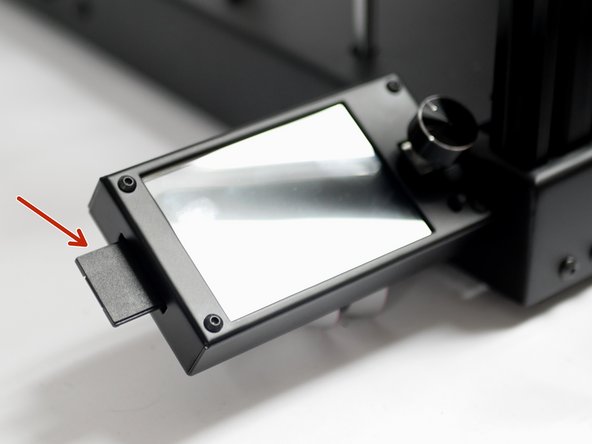
With the printer powered down, insert the SD card into the display with the adaptor.
-
-
-
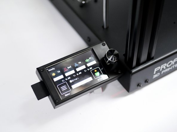
Powering on should result in the touch screening being updated. The update can take a few minutes.
-
Note, if you get a bed mesh error, that is normal, as no bed mesh has been set yet.
-
-
-
If your touch screen shows an Illegal flash app error:
-
1. Wipe the SD card and put an empty text file named reset.txt onto it.
-
2. Power off the printer, insert the SD card into the display and power on again.
-
3. After the reset, power down, wipe the SD card, and copy the firmware files again and retry the installation.
I wanted to update my post but can’t do because of the 5 minutes limit. So here is the Update
Electronics fan and LEDs work fine.
I heated the nozzle to 60°C but the Hotend cooling fan isn’t spinning at any time (nozzle temp was over 90°C). Connected to an other 24V pin the fan is running. What can i do?
Update was successfull. I had to reverse the two white display cables to get the Display to work.
Because of the identical dimensions in X and Y, more an issue than a Problem: I checked the wiring but my X-axes was moving in the wrong direction (X- was running to the right and X+ to the left). So Homing X would end in a crash at the right side. I change the two motor cables with each other but that converts X in Y and Y in X.
Now i changed the right motor cable to one that have no crossed cables. My X and Y is reversed now so that i had to reverse the limit switches too. But its ok for the moment because both have 300mm length.
Thank You
The Hotend cooling fan is’nt spinning at any time, Electronics fan and LEDs work fine. Update was successfull but after it the display is just blinking (background light). Idownloaded the file again,checkthe filesize onthe image above but all the same. What can i do?
Thank You
-
-
-
Once the touch screen has been updated remove the SD card.
-
Delete the contents of the SD card, it should now be ready to use with your printer.
-
-
-
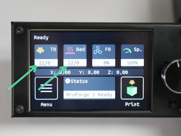
Thermistors should read room temperature.
-
You may find that the hotend thermistor is a little off/jumpy, that's OK as it's a high temp thermistor and designed to be accurate at temps above 100C.
-
-
-
Before starting, make sure that none of the endstops are being triggered.
-
Click on Menu
-
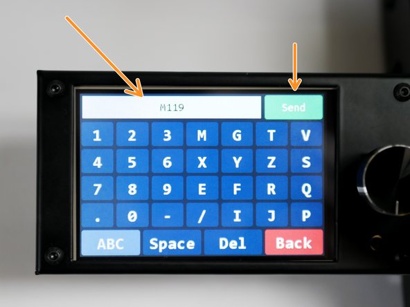
Select terminal.
-
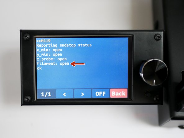
Send an M119 command.
-
You should receive back that X and Y endstops are open.
-
The Z probe should also be open, and the filament sensor should be triggered (as there's no filament loaded).
-
-
-
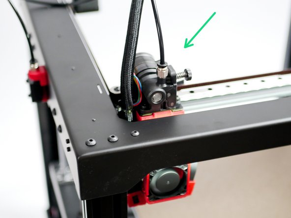
Move the tool head to the bottom left as shown.
-
Both the X and Y endstops should be triggered.
-
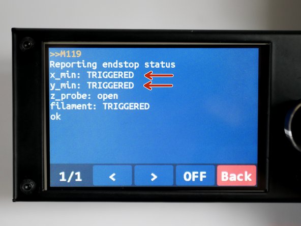
In the terminal, send the M119 command again.
-
You should receive the following back with the X and Y endstops reporting as triggered.
The y endstop cannot be triggered as the carriage bumps into the frame before the gantry gets close to the microswitch.
What have I done wrong ?
Could you please post the issue on the forum with an image, if you’ve not already. Thank you.
-
-
-
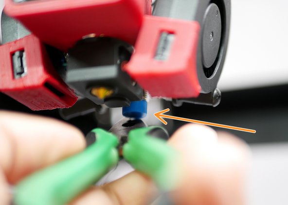
Use a piece of filament to check that the sensor is working.
-
Sending M119 should return back OPEN.
-
-
-
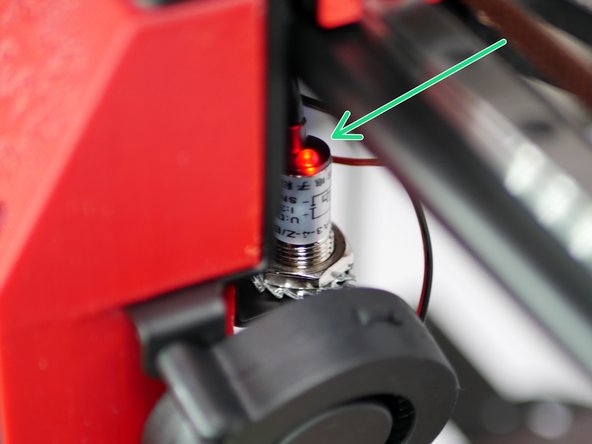
Place a metal object underneath the probe.
-
The LED on the probe should now light up.
-
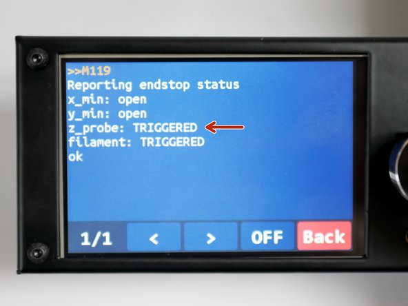
With the metal object still under the probe, send the M119 command again - it should return as TRIGGERED.
-
-
-
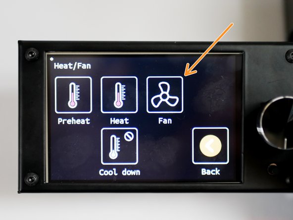
In the menu screen, go to Heat/Fan
-
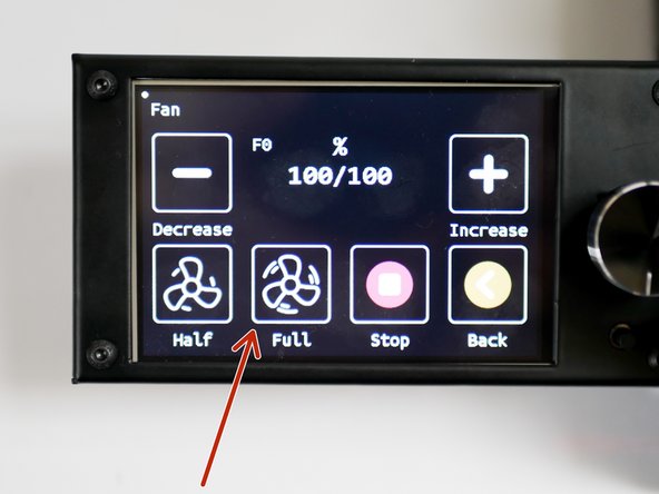
Click on Fan
-
Set fan to Full
Is it normal for fans to have a whine noise when it is 1% to 99%? I believe this is a speed controlling noise correct? Sounds like my R/C car’s throttling.
-
-
-
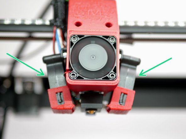
Both part cooling fans should be spinning.
-
Switch the fans off when done.
-
-
-
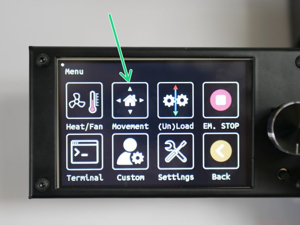
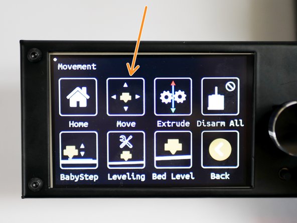
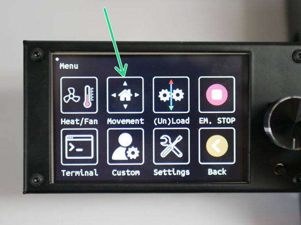
In the menu go to Movement
-
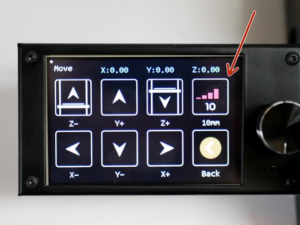
Click on Move
-
Set the motion increments to 10mm.
-
Use the buttons to move the X, Y and Z axes around and confirm that the printer is making the desired movements.
-
-
-
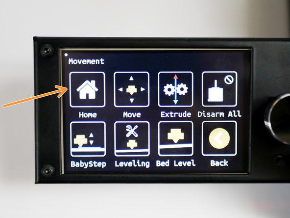
Go to the Movement menu
-
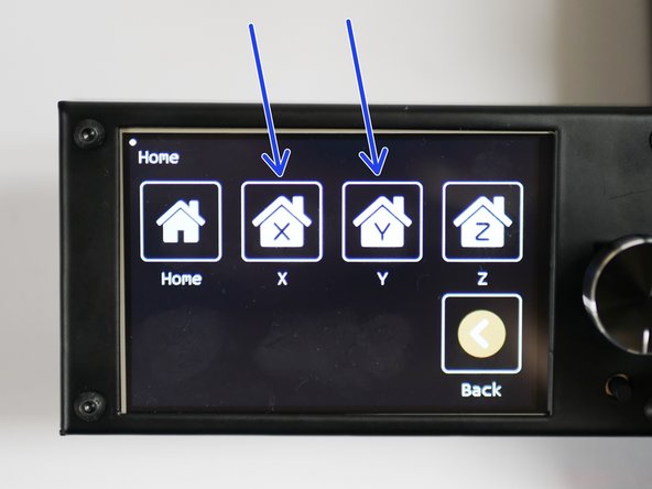
Click on Home
-
Home X and Y
-
The printer should home those axes.
-
-
-
Before starting, place the flexplate onto the heated bed, if you've not already done so.
-
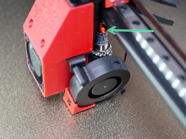
Before homing the Z-axis, manually raise the platform to meet the tool carriage at the centre of the print platform.
-
Before being able to move the carriage by hand, you will need to disable the stepper motors. This button can be found in the movement menu (Disarm All).
-
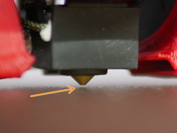
The platform should trigger the probe (red light comes on) before the tip of the nozzle touches the flexplate.
-
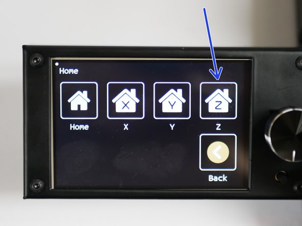
With the above confirmed, home the Z-axis from the display.
I have the same problem. When I move 10mm in X and Y the printer head actually moves 20mm in Z it is the other way around and it moves only 5mm. The jumpers are set correct (checked 3 times). I’m currently paying around with the steps per mm setting in the “settings/machine/settings/steps per mm sub menu” and have adjusted the values to 80 for X and Y and to 800 for Z not knowing if these are the correct values.
Double check that you have the 0.9degree motors moving the x/y axes and 1.8degree motors moving the Z axis.
Homing Z results a displacement of the printerhead to its maximum value of X and Y, so that the probe is outside the platform. When the platform raises, it pushes to the left ventilator and I have to perform a emergency stop by the power switching off.
I also noticed that the step of 10 mm in X or Y direction is more than 10 mm.
Finally I couldn’t perform the Z homing. And for the same reason I couldn’t perform the Probe Offset.
Power off the printer and double check that the jumpers are correctly installed underneath the stepper drivers. You can find this in the wiring stage.
Is there anybody from Makertech with some help or advice?
-
-
-
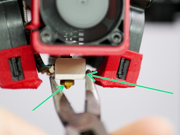
With the hotend hot, hot tighten the nozzle.
-
Do this using two pliers. Use one to hold the heater block, use the other to tighten the nozzle.
-
Be careful doing this, the hotend is hot enough to cause burns!
-
-
-
With the hotend hot you can send an extrude command to check the extruder.
-
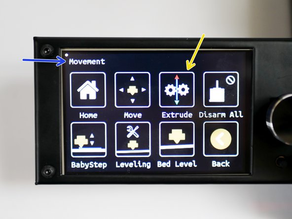
In the main menu go to Movement
-
Then go to Extrude
-
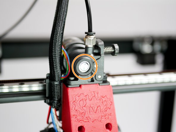
Orbiter Extruder:
-
Load: Turn clockwise
-
Unload: Turn anticlockwise
-
-
-
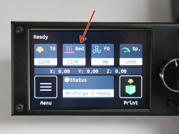
From the home screen, click on Bed
-
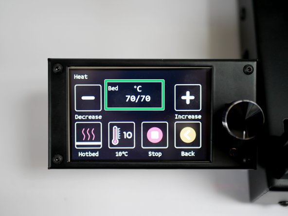
Heat the bed to 70C.
-
MIC-6 NOTE: The printer reads the temperature of the silicone heater, not the platform. Therefore, even though the printer may report back that it has reached its temp, it will take approx 5-10 min for the platform surface to actually reach that temp.
-
-
-
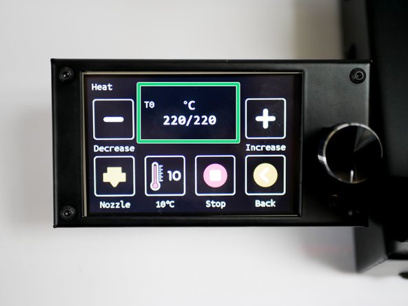
Before beginning this step, make sure that the heated bed and hotend are heated up to your desired printing temp. We recommend 220C on the hotend and 70C on the heated bed as a good starting point.
-
The hotend and platform, when hot, would have expanded. Therefore, the z-offset is different for when the printer is hot versus cold.
-
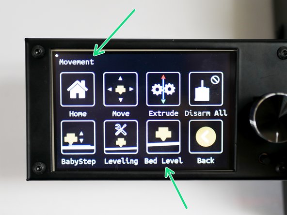
Go to the Movement menu and then to the Bed Level menu.
-
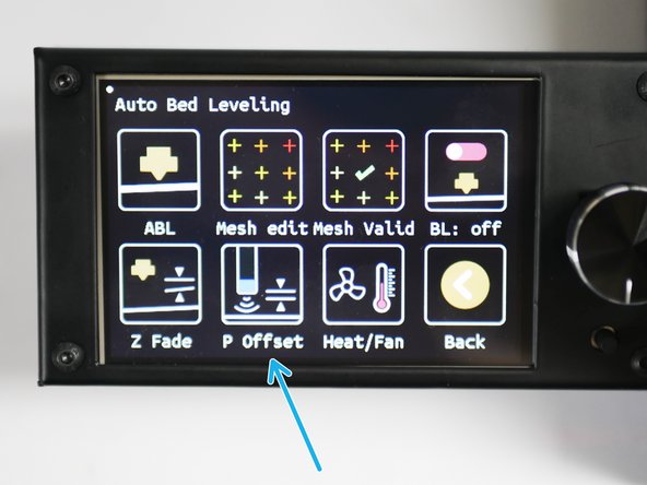
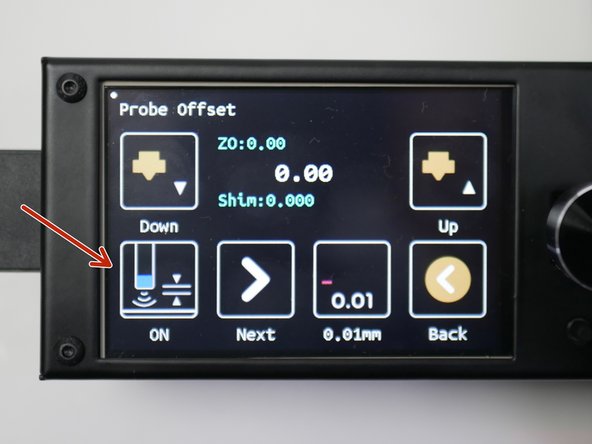
Click on P Offset
-
Press ON to begin the offset calibration.
-
-
-
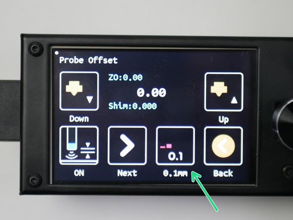
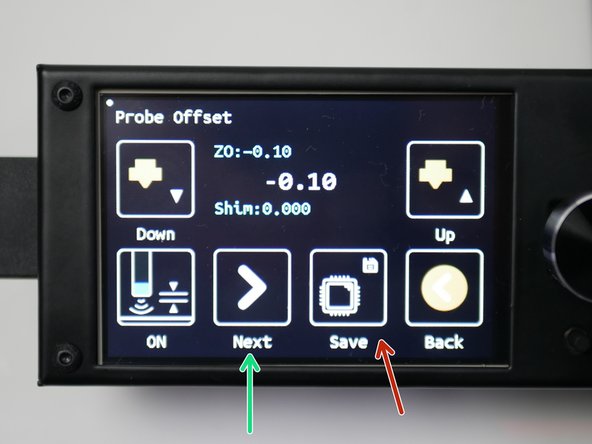
Toggle the adjustment increment to 0.1mm.
-
Place a sheet of paper under the nozzle.
-
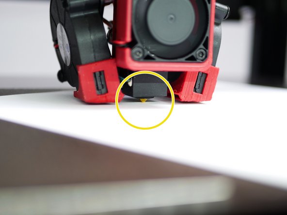
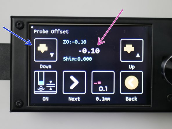
Lower the nozzle (raise the bed) in 0.1mm increments until the sheet of paper is trapped between the nozzle and platform. Feel free to drop down to 0.01mm for finer tuning.
-
In our case, we had to lower the nozzle by just 0.1mm before this happened.
when I press ‘on’ it the print head moves but the button on the touch screen doesnt change, it stays as ‘off’.
after calibrating with the sheet of paper I save the setting, which seems to save ok.
but then when I go to the next step, auto leveling, the print head moves around in a square of about 100mm and says ‘bed leveling failed’ at the end of the process.
Does the auto leveling move aroud the whole bed? If so it seems to think that the bed is about 100mm square?
Anyone got any ideas?
We’ll look into this and see if we can recreate the error. Are you running a MIC-6 platform?
-
-
-
Press next until the save button appears.
-
Press the save button and then press OK to save the offset to the printers' memory.
-
-
-
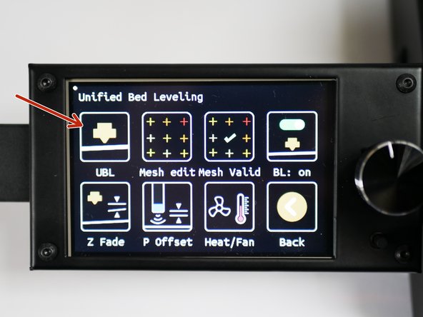
In the Movement -> Bed Level menu, click on UBL
-
Click Start
-
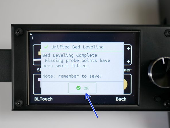
The Proforge 3 should then run through the auto-levelling procedure.
-
Click OK when done.
I got the Preassembled Printer, all tests so far where successful.
However Bed Leveling always fails.
I am 99% certain that it is because my Print-Bed is really visibly crooked and it seems the bed-leveling only moves the bed a certain amount which is not enough to get to the point the z-endstop triggers for some probe points.
Any idea what i can do to manually get the bed more level by default? The Bed has no spring leveling system like some other printers. Only idea i had so far is adding some washers to one side to get the bed a bit higher on one side.
-
-
-
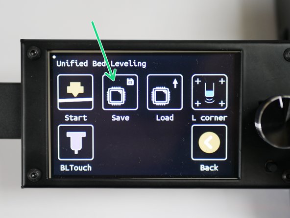
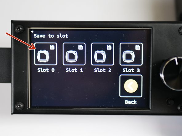
Click Save to save the mesh.
-
Save to slot 0
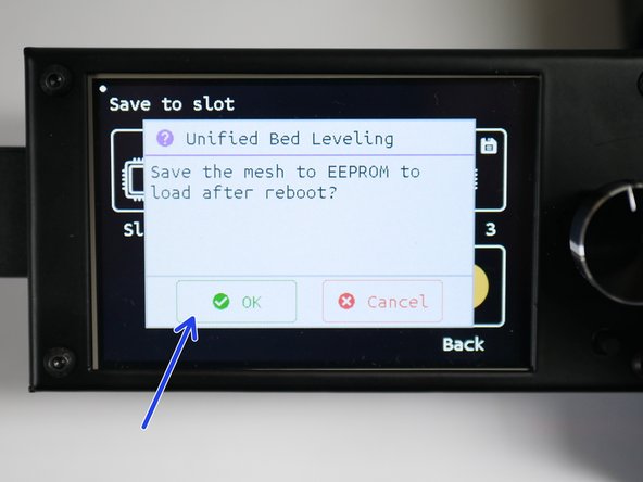
-
Press OK to confirm the save.
-
-
-
With all of these steps now completed, you are ready to begin your first print.
-


Cancel: I did not complete this guide.
2 other people completed this guide.
Attached Documents

2 Comments
The drill hole for the included HW-273 board is missing. You got it on the pictures, but it is not drilled
That board mounts to the side of the PSU with the 3d printed mount. Instructions for it are to be released soon in the OctoPi guide.