Reputation over time
It looks like this user hasn't gained any reputation yet.
Once they have, you'll be able to view a graph of their reputation gained over time.
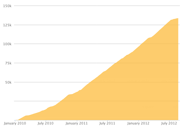
Here's a preview of what the graph will look like:
Reputation Breakdown
No reputation gained yet.
237
Remove the 630mm extrusions from the -platform and attach them individually to the Z brackets. Then, you can align the extrusions flush with the brackets. Finally, drop the rest of the platform onto the 630 mm extrusions and then center it up.
After tightening everything up, I found it easier to remove the 630mm extrusion and attach it to the Z bracket in step 18. It is much more difficult to handle the platform fully assembled.
I found it best to loosen the corner brackets from step two to get good alignment and then retighten the bolts on the corner brackets.
Start all four bolts in the rubber feet and only add a few turns to line them up. You need to have some space between the frame and the base. Otherwise, you will not have space to start the 4th and final bolt, as the hole in the base is less than a millimeter or so off. That is enough that you cannot run the bolt in if the base is pressed to the frame.
I found that if you level the bottom of the bolt with the top of the nut gave the best result. if you over tighten it will curve the pad.
I was a bit confused by this diagram at first. I thought I would clear up what is going on power-wise. The bed heater takes AC power, so the DC output for the heater bed from the octopus board triggers a relay from the printer board. The relay connects the neutral and line, and energy flows into the heater. The heater pad probably gets hot fast as it's 110v in the USA and 220v in the EU vs. 48v DC out of the board.