-
-
Complete this stage:
-
If you are upgrading from an already built Proforge 2/2S Single Extruder setup.
-
Skip this stage and continue here:
-
If you are building the Dual Switching Extruder from the Proforge 2/2S build guides
-
-
-
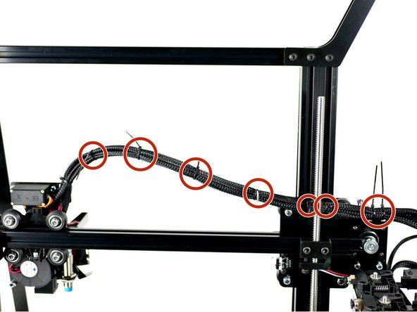
Push the Extruder Carriage out as far as it will go.
-
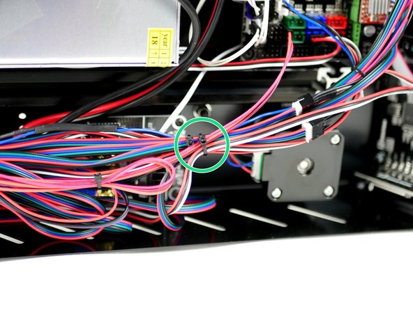
Use cable ties to bunch together the cables up to the Z-axis Bracket.
-
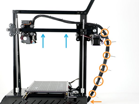
Raise the gantry to its highest position on the frame.
-
Use cable ties to bunch together all of the cables down to the base and feed into the base through the square hole.
-
-
-
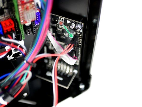
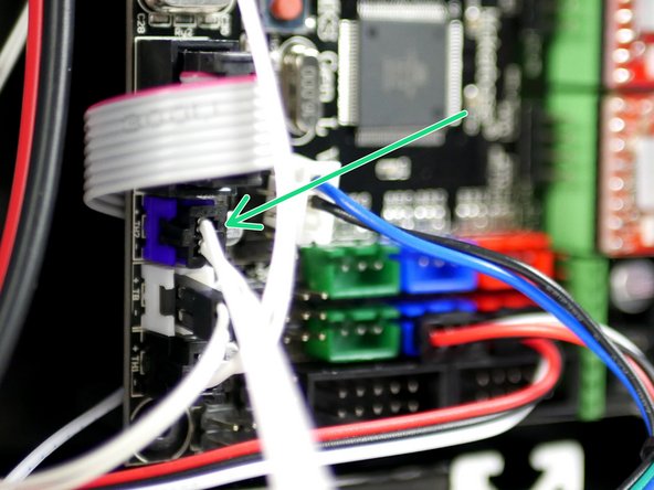
Connect the 2nd filament sensor cable to the touch screen.
-
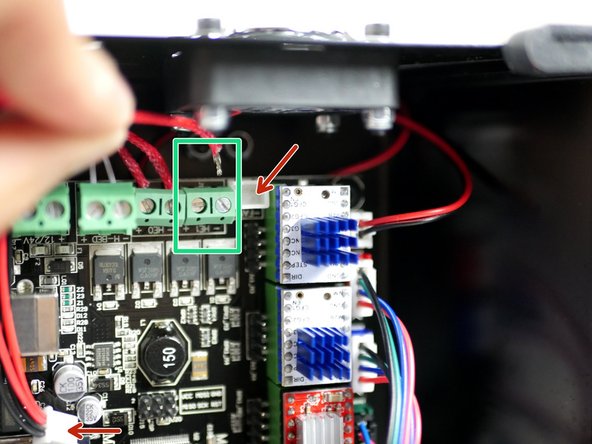
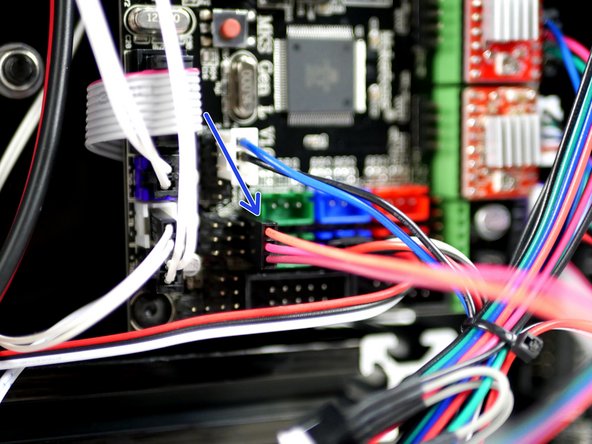
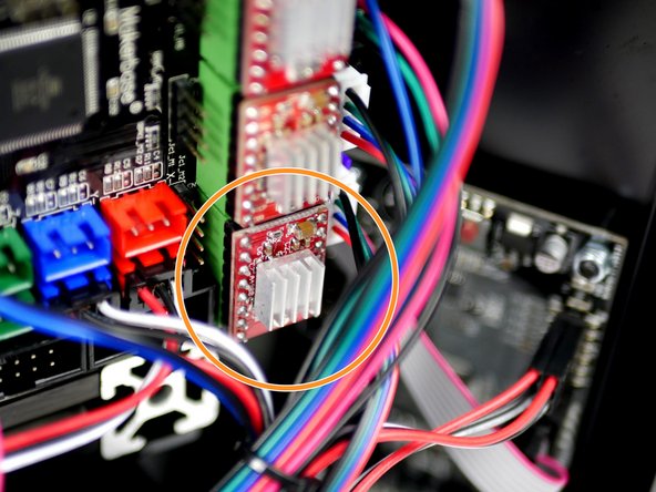
Connect the 2nd extruder motor cable to the main board in the E1 position.
-
-
-
Connect the Hotend heater cables to the electronics board.
-
Unplugging the print fan cable for the board should give you better access.
-
If you're struggling to the get the cables in, removing the electronics board from the base will give you better access to the terminals.
-
-
-
Connect the hotends thermistor to the electronics board (TH2).
-
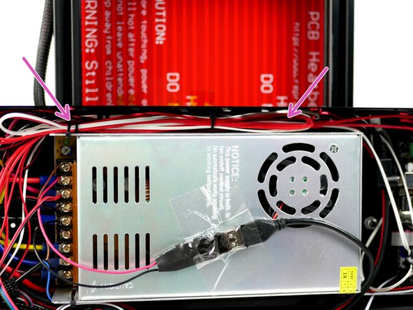
Connect the hotends fan cables directly to the power supply terminals.
-
Red to Positive
-
Black to Negative
-
-
-
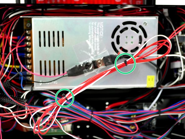
Cable tie together the Hotend cables making sure not to have any sharp bends in the cables.
-
Tuck the cables in between the side panel and power supply.
-
Cable tie the cables to the power supply to hold in place.
-
-
-
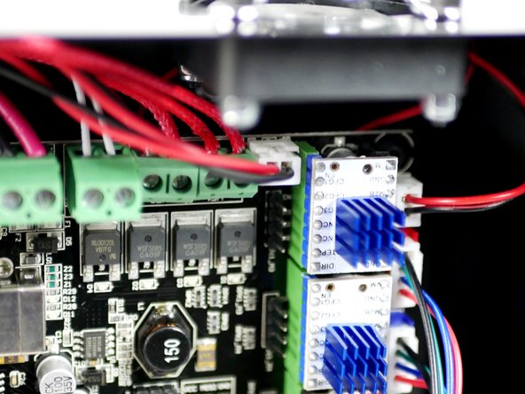
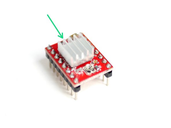
Prepare the A4988 Stepper Driver by sticking the heatsink to the black chip on the driver.
-
Make sure that the heatsink is not touching any of the pins. Orient the fins of the heatsink as shown.
-
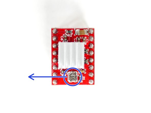
Adjust the trimpot so that the flat side is facing left, like shown in the second image.
-
Fix the stepper driver onto the electronics board, matching the orientation shown in the third image.
-
Installing a stepper driver the wrong way round will destroy it.
-
-
-
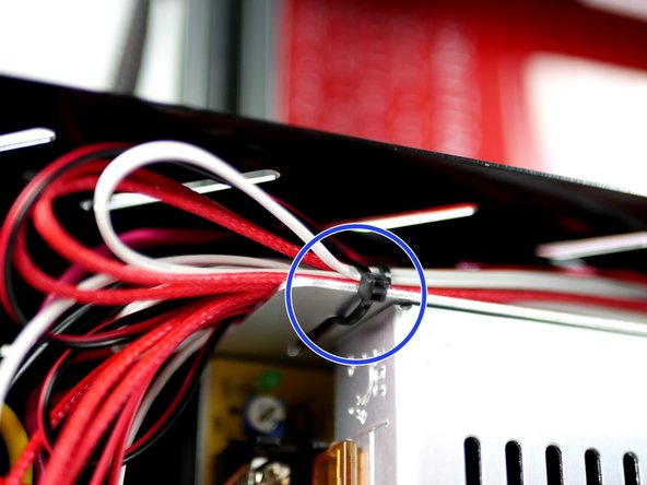
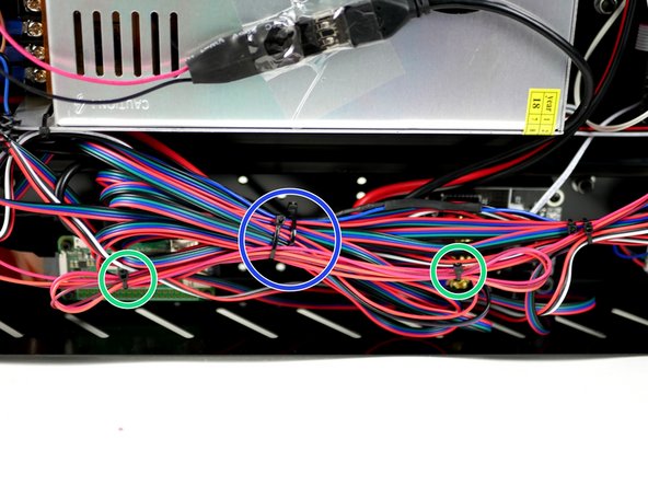
Use cable ties to loop and tie the loose cables.
-
Cable tie this loop to the original loop.
-


Cancel: I did not complete this guide.
9 other people completed this guide.
