Parts
No parts specified.
-
-
Fix one of the NEMA 17 motors to the base like shown.
-
Nema 17 motor
-
M3 x 6mm
-
The cable connector should to be facing upwards.
-
-
-
Align the Z-Pillar to the base like shown in the first image.
-
Align a Motor underneath it also with the connector pointing upwards.
-
Fix everything together with four M3 x 6mm bolts.
-
-
-
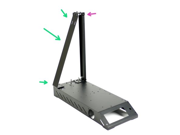
Take the Z-Pillar and align it into position with the base assembly.
-
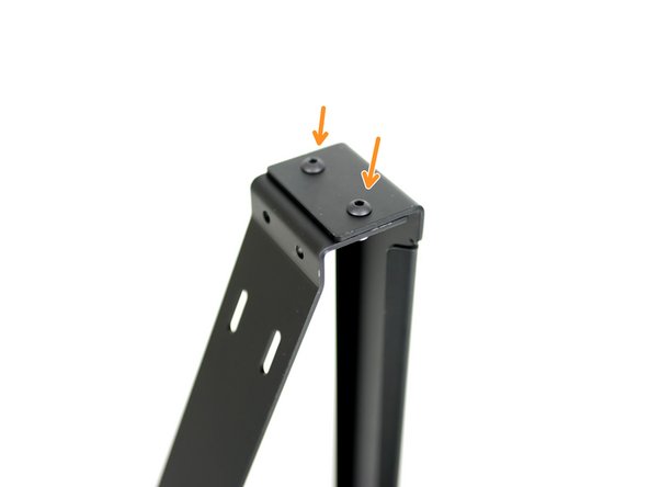
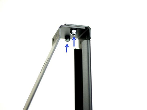
Fix the top of the support pillar to the main pillar with two M4x10mm bolts and M4 nyloc nuts.
-
M4 x 10mm bolt
-
M4 Nyloc Nut
-
-
-
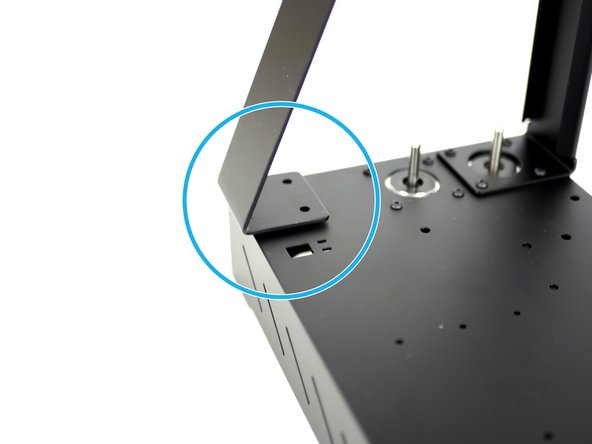
Fix the support pillar to the base.
-
M4 x 10mm bolt
-
M4 nyloc nut
-
-
-
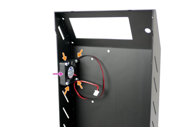
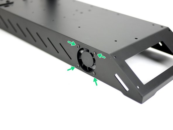
Fix the 40mm electronics fan onto the side of the base.
-
M3 x 16mm bolt
-
M3 nyloc
-
Ensure that the sticker side is facing into the base.
-
-
-
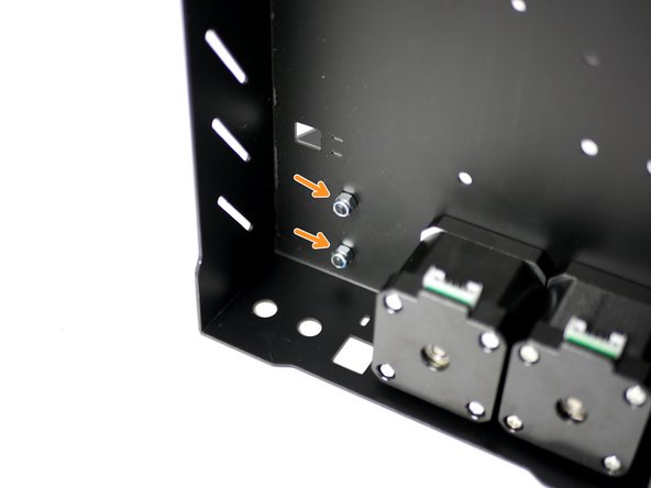
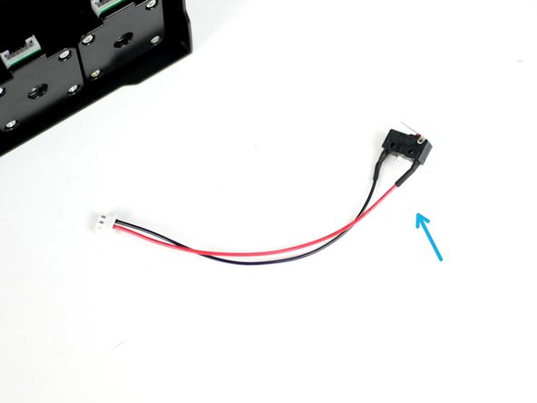
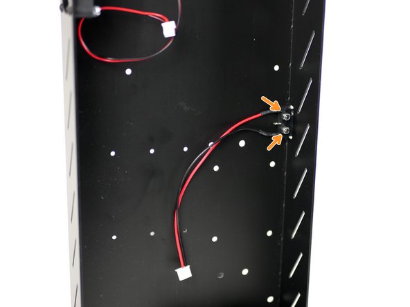
Fix the X-Endstop (it is the one with the shorter cable) to the inside of the base.
-
M2.5mm bolt
-
M2.5 nyloc nut
-
Make sure that the switch's lever is pointing towards the back of the base.
-
-
-
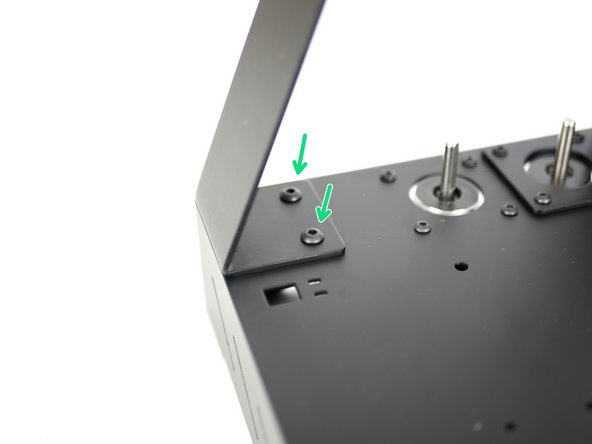
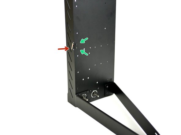
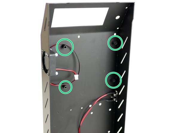
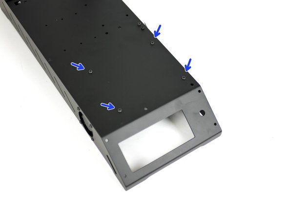
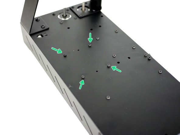
Fix the control board mounts onto the inside of the base like shown.
-
M3 x 10mm stand-off
-
M3 x 6mm bolt
-
-
-
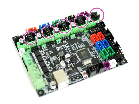
Take the MKS Gen_L v2 control board out of its packaging. Avoid doing this on carpet or when wearing socks on carpet as static could damage the board.
-
Touching a large metal object will ground you.
-
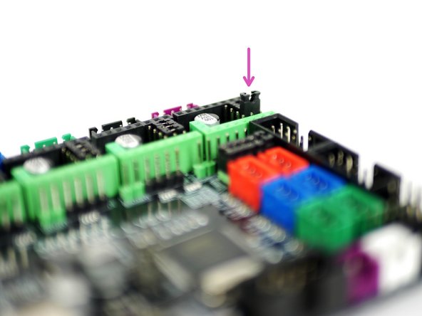
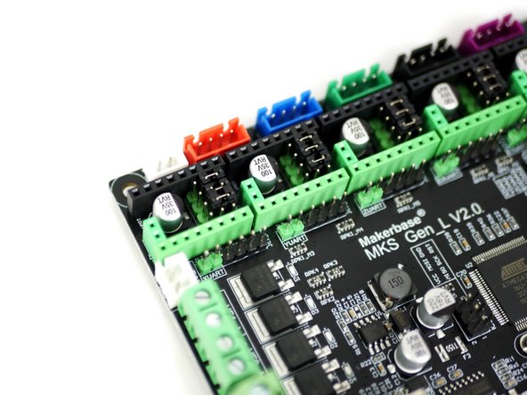
Install the jumpers as shown on all of the motor positions on the board.
-
-
-
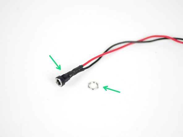
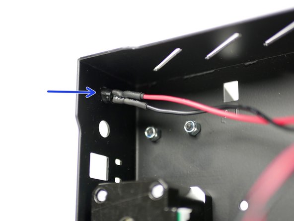
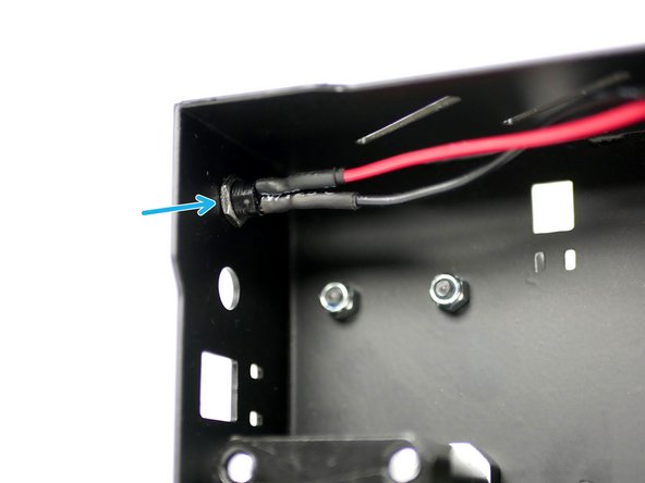
Take the power port mount and remove the nut.
-
Thread it into the back of the base through the hole nearest the base side.
-
Fix it in place by re-threading on the nut.
-
-
-
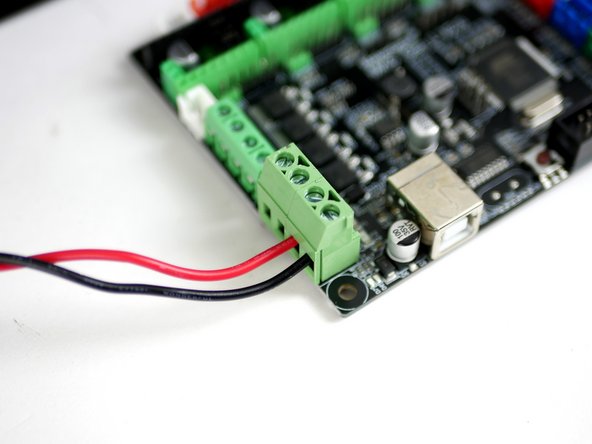
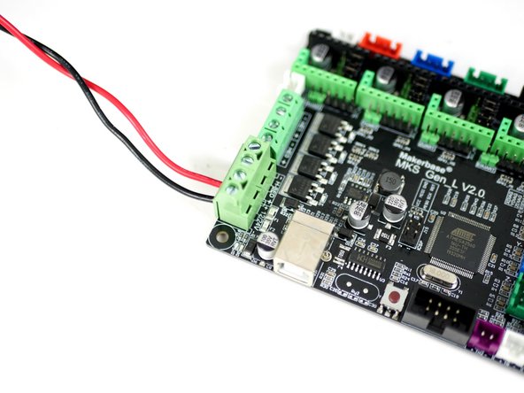
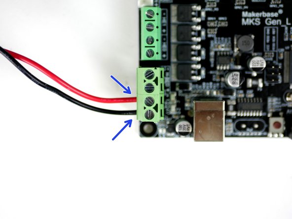
Using a small flat head screw driver fix the power cables into the control board like shown.
-
Red cable to positive and black to negative.
-
-
-
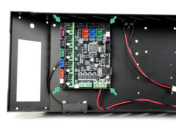
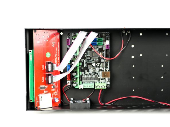
Fix the control board onto the mounts. Make sure to match the orientation shown in the image.
-
M3 x 6mm bolt
-
Don't over tighten these bolts, over tightening can cause the board to warp and become damaged.
-
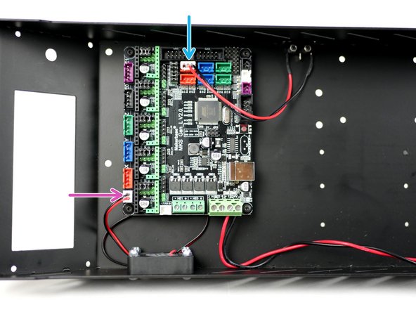
Connect the fan to the control board.
-
Connect the X-Endstop to the control board.
-
-
-
Complete this step even if you do not have the LCD screen upgrade.
-
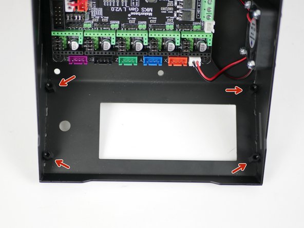
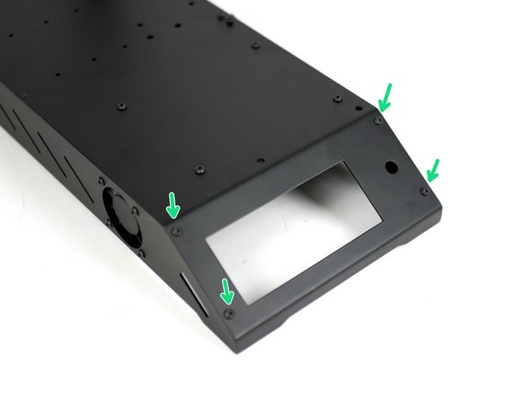
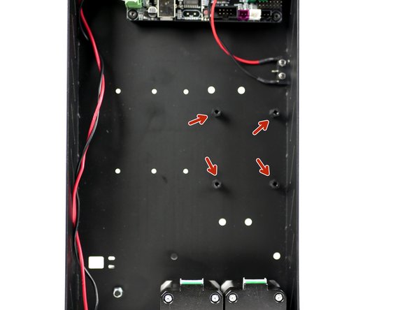
Fix the LCD screen mounts onto the base.
-
M3 x 10mm stand off
-
M3 x 6mm bolt
-
-
-
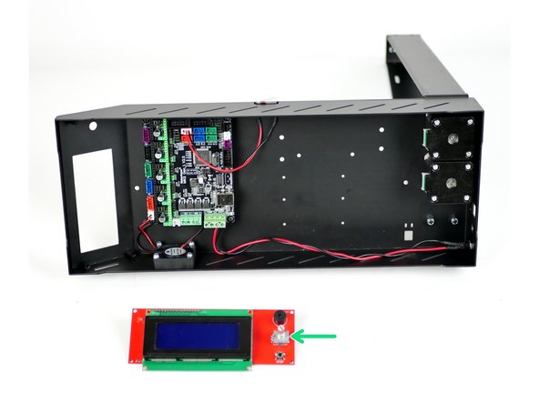
Take the LCD screen out of its packaging. Like with the control board, avoid doing this on carpet or when wearing socks on carpet as static could damage the board.
-
Touching a large metal object before handling will ground you.
-
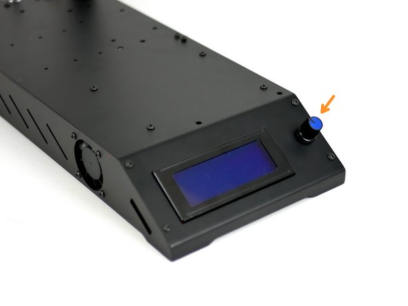
Start by removing the control knob from the screen.
-
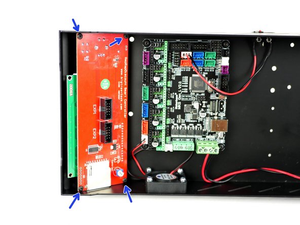
Mount the screen like shown.
-
M3 x 6mm bolt
-
Fix the control knob back on.
-
-
-
Connect the cables from the LCD screen to the control board like shown.
-
-
-
Complete this step even if you do not have the heated bed upgrade.
-
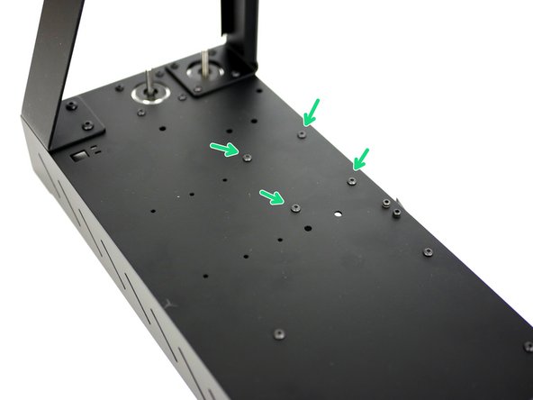
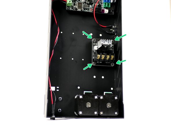
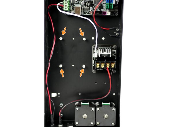
Like the control board, fix the MOSFET stand-offs onto the base in the position shown.
-
M3 x 6mm bolt
-
M3 x 10mm standoff
-
-
-
Mount the MOSFET onto the base. Make sure that the power terminals are facing towards the motors.
-
Four M3 x 6mm bolts
-
-
-
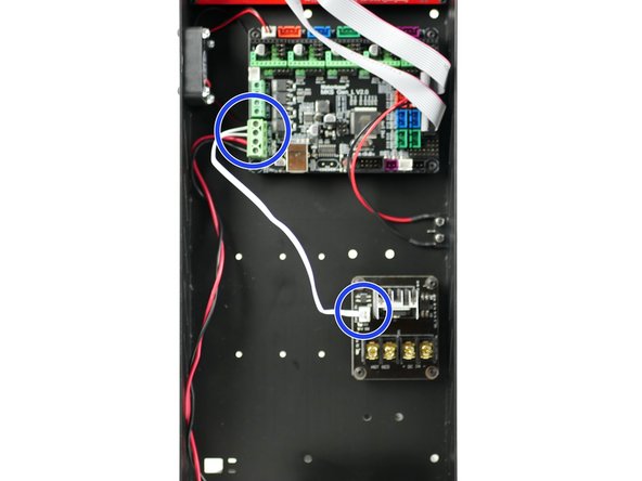
Connect the short white signal cable from the MOSFET to the control board.
-
The polarity into the control board doesn't matter.
-
You may find it easier to install by unmounting the control board first.
-
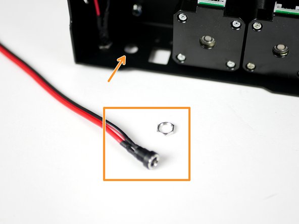
Fix the power mount for the heated bed in the same way as before.
-
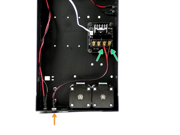
Connect the power mounts cables to the MOSFET like shown. Red to positive and black to negative.
-
-
-
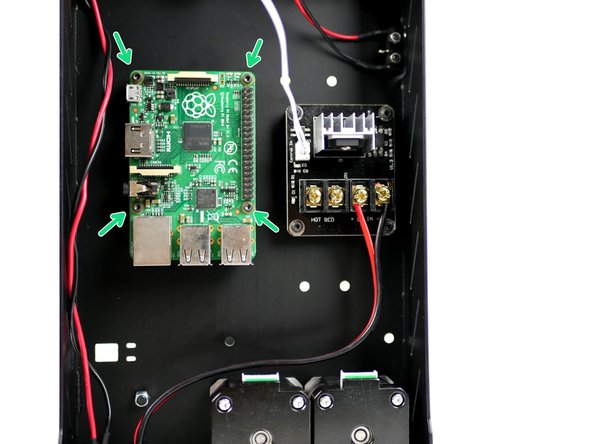
Mount the Raspberry Pi 3B+ in the position shown.
-
Fasteners can be found in the OctoPi upgrade.
-
M2.5 x 6mm bolt
-
M2.5 x 10mm stand-off
-