-
-
Box A - Frame
-
Box B:
-
Docking Bracket
-
Gantry Assembly
-
Idler bearings
-
Idler Fasteners
-
-
-
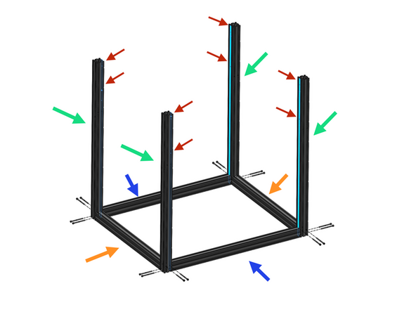
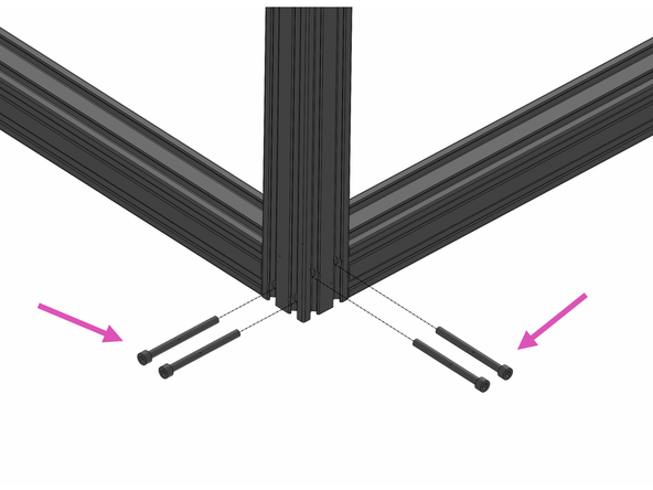
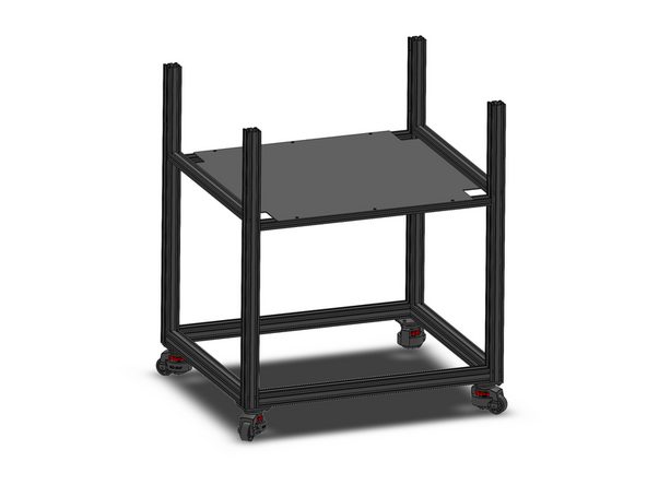
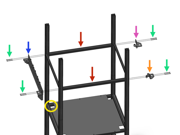
Start by assembling the lower part of the frame as shown in the diagram.
-
4040 - X - 680mm
-
4040 - Y - 570mm
-
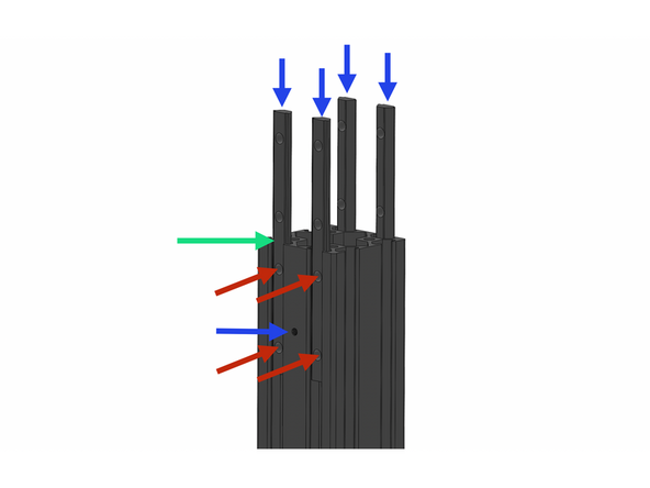
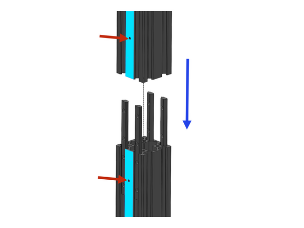
4040 - ZB - 800mm
-
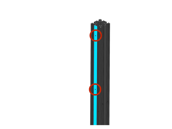
The ZB extrusion will only have two M3 threaded holes on its side. Ensure these are facing inwards as shown in the diagram by the red arrows.
-
M5 x 60mm Bolts
-
-
-
Fix 2 2040 extrusions as shown.
-
2040 - X - 680mm
-
These should NOT have any tapped M3 holes on their side.
-
M5 x 60mm Bolts
-
-
-
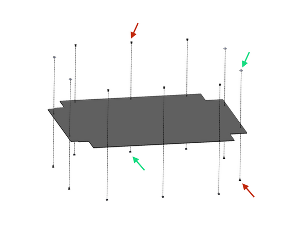
If you have the enclosure prepare the bottom panel as shown, otherwise skip this step.
-
The panels can be found in Box C.
-
Enclosure fastener kit can be found in Box B
-
Peel away the protective film and loosely fasten the nut to the bolt.
-
M5 x 6mm Bolt
-
M5 T-nut
-
Note the orientation of the bolts and nuts in the diagram, the ones on the short sides are flipped.
-
-
-
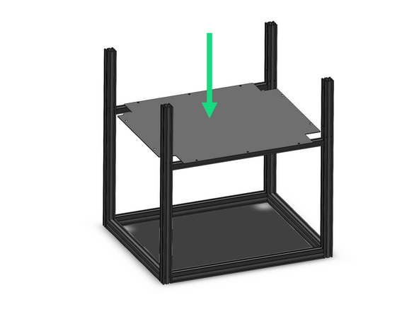
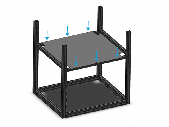
Drop the panel into place but to not secure it to the frame yet.
-
-
-
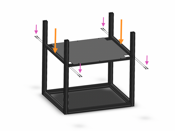
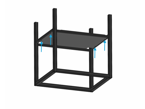
Fix the remaining two z-support beams
-
2040 - Y - 570mm
-
M5 x 60mm
-
Align the t-nuts to the slots in the 2040 extrusions and tighten the bolts to lock the T-nuts against the grooves of the extrusions, securing the panel in place.
-
-
-
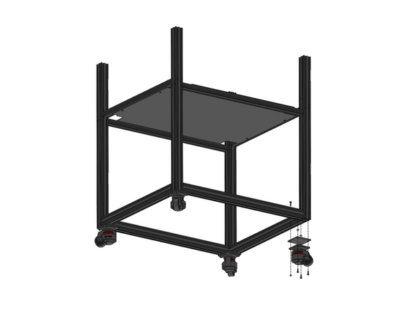
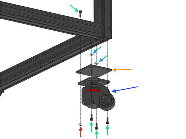
Install the four wheels to the bottom of the frame assembly.
-
M5 x 14mm
-
Wheel Bracket
-
Wheel
-
M5 T-Nut
-
M5 Nylon Nut
-
-
-
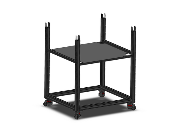
Add to each the ZB extrusions 4 connector links.
-
Secure them in place with the included M5 Grub screws.
-
Set the connectors half way into the grooves on the extrusions.
-
Secure two on the inside face (the face with the M3 tapped holes), and two on the outside face of the extrusion.
-
-
-
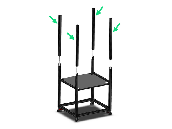
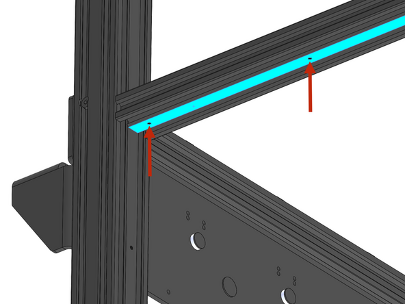
Secure to the connector links the ZA 4040 Extrusions.
-
4040 - ZA - 800mm
-
Drop the extrusions onto the connectors and secure in place with grub screws.
-
The ZA extrusion will have three M3 threaded holes on its side. Ensure these are facing inwards as shown in the diagram so to line up with the M3 threaded holes on the face of the ZB extrusions.
-
-
-
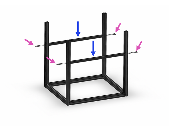
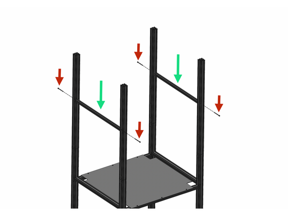
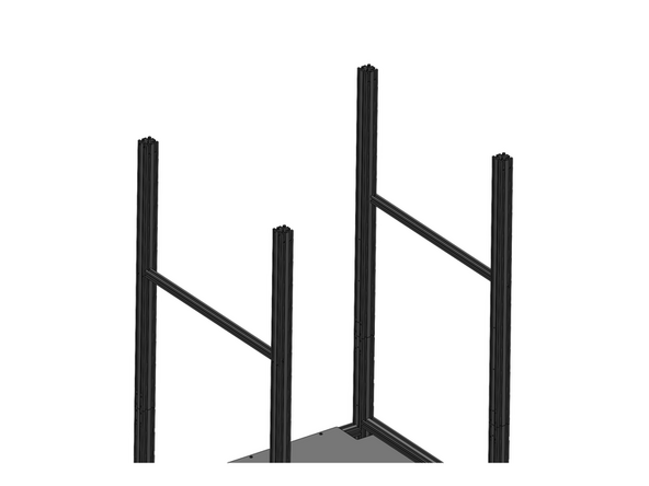
Fix to the frame the two Y-support extrusions.
-
2020 - Y - 570mm
-
M5 x 60mm
-
-
-
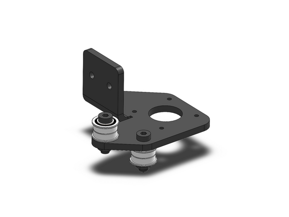
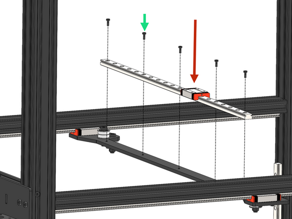
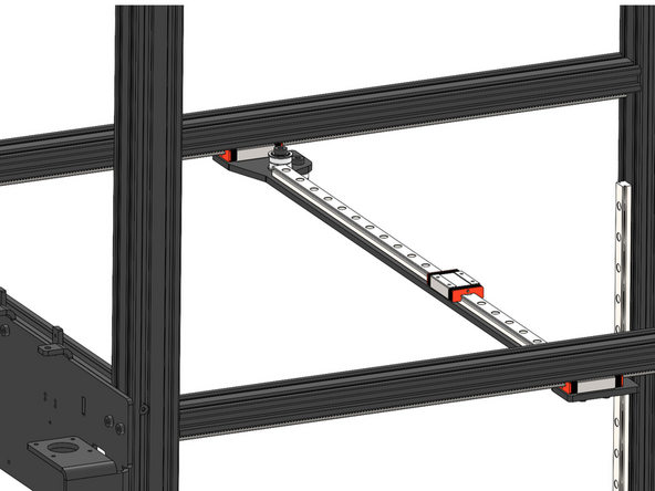
Prepare the dock bracket by loosely fastening these bolts.
-
Dock Bracket (Box B)
-
M5 x 8
-
M5 T-Nut
-
-
-
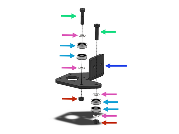
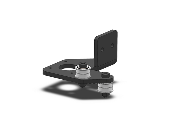
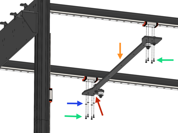
Assemble the belt idlers to the front motor bracket. Fasteners and bearings can be found in Box B.
-
Front Motor Bracket
-
M6 x 25mm
-
M6 12x0.5mm Shim
-
F606ZZ Bearing
-
M6 Nyloc
-
-
-
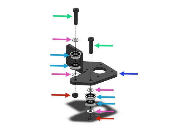
Assemble the belt idlers to the rear motor bracket.
-
Front Motor Bracket
-
M6 x 25mm
-
M6 12x0.5mm Shim
-
F606ZZ Bearing
-
M6 Nyloc
-
-
-
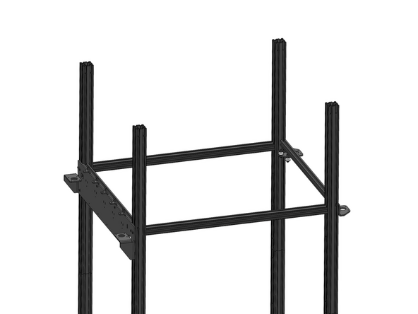
Fix the three brackets to the frame as shown.
-
2040 - X-Rail - 680mm
-
Ensure that the extrusion is mounted with the M3 tapped holes facing downwards.
-
Dock Bracket (Left Side)
-
Mount to the left side of the frame, if you have the enclosure panel installed, this will be the side with the small notches (for cables).
-
Rear Motor Mount
-
Front Motor Mount
-
M5 x 60mm Bolt
-
-
-
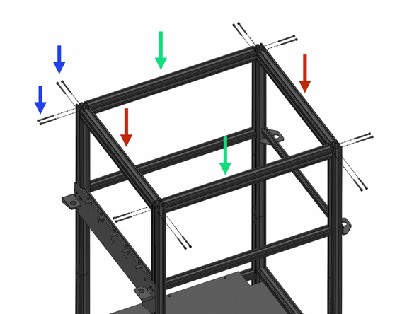
Complete the Frame by securing the remaining 4040 extrusions to the top.
-
4040 - X - 680mm
-
4040 - Y - 570mm
-
M5 x 60mm
-
-
-
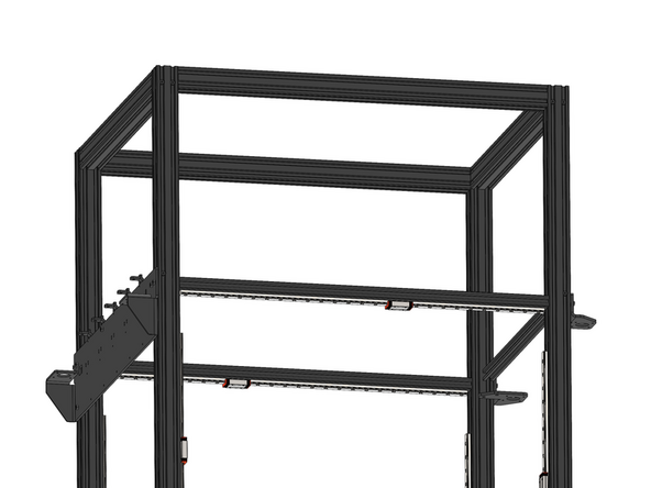
Secure to the frame four Z-Rails.
-
MGN12H Rail - 560mm
-
M3 x 8mm
-
Ensure that the rubber stoppers are secure on the ends of the rails to prevent the carriage from falling off.
-
Take care when tightening to not strip the threads on the extrusion by applying too much force.
-
-
-
Secure to the frame two X-Rails.
-
MGN12H Rail - 670mm
-
M3 x 8mm
-
Ensure that the rubber stoppers are secure on the ends of the rails to prevent the carriage from falling off.
-
Take care when tightening to not strip the threads on the extrusion by applying too much force.
-
-
-
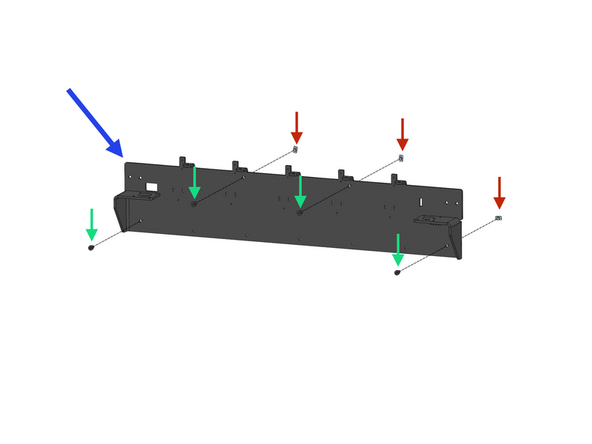
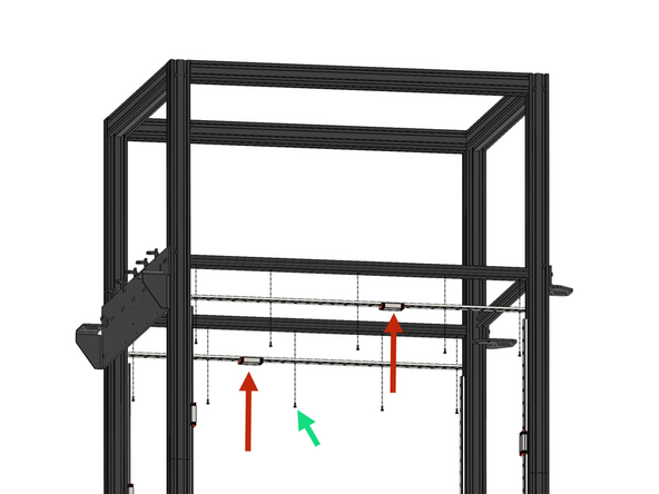
Fix the Gantry to the X-Rail carriages as shown.
-
The gantry is not symmetrical and the side with the notch cut-out and slotted holes should point to the rear of the machine!
-
Gantry Idlers come pre-assembled here however double check all 4 are tight but still able to spin and also match the image.
-
Gantry (Box B)
-
M3 x 8mm
-
M3 Shim
-
-
-
Secure to the gantry the Y-Rail.
-
MGN12H Rail - 500mm
-
M3 x 8mm
-
Ensure that the rubber stoppers are secure on the ends of the rails to prevent the carriage from falling off.
-
Take care when tightening to not strip the threads on the bracket by applying too much force.
-

Cancel: I did not complete this guide.
11 other people completed this guide.
