
-
-
For this upgrade you will need a Raspberry Pi board. We recommend the Raspberry Pi 4 2GB for this.
-
Compatable boards:
-
Pi 3B+ (USB WiFi adapter required)
-
Pi Zero 2 W
-
There is a current shortage for these boards. Supply is returning, but we're struggling to secure any in bulk. You should be able to find local distributors selling them on a one per customer policy.
-
-
-
Fix the four Raspberry Pi standoffs to the Base with four M2.5 x 6mm bolts.
-
M2.5 x 6mm bolt
-
M2.5 x 10mm standoff
-
-
-
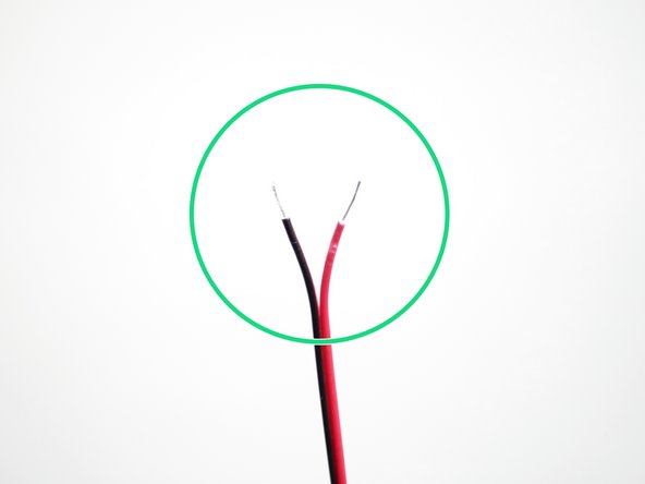
Strip both ends of the black and red power cable.
-
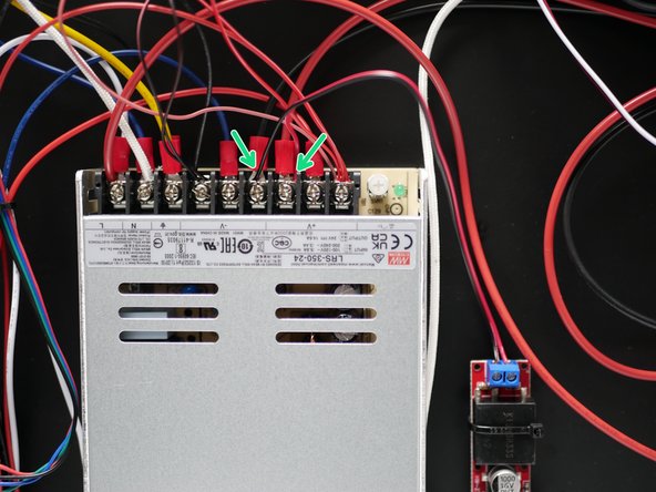
Connect one side to the USB power adapter as shown. Red on the left side, black on the right.
-
-
-
Due to an unfortunate oversight, you may have an M3 x 20mm bolt instead of an M4 x 20mm bolt and the 3D printed KIS3R33S bracket will have a 3mm hole instead of a 4mm hole. If this is the case see the next step.
-
Take the KIS3R33S bracket and use it to mount the USB adapter to the side of the PSU with an M4 x 20mm bolt.
-
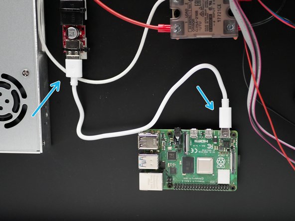
Connect the wires to the +/- terminals as shown. Red to positive and black to negative.
-
-
-
Use two cable tie mounts to secure the KIS3R33S USB adapter to the base.
-
Connect the wires to the +/- terminals as shown. Red to positive and black to negative.
-
-
-
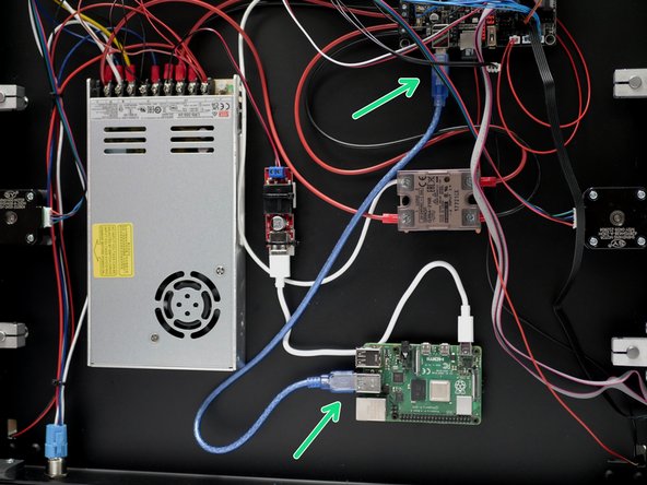
Connect the blue USB cable from the BTT control board to the Raspberry Pi board.
-
-
-
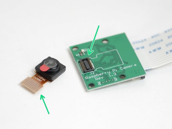
Unclip the camera from the Pi Cam board.
-
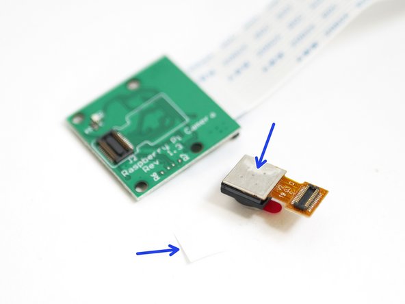
Peel away the protective layer from the sticky pad underneath the camera module.
-
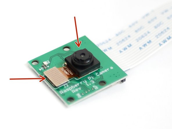
Secure the camera module back onto the baord.
-
Secure the connector first, then press the camera down.
-
-
-
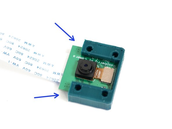
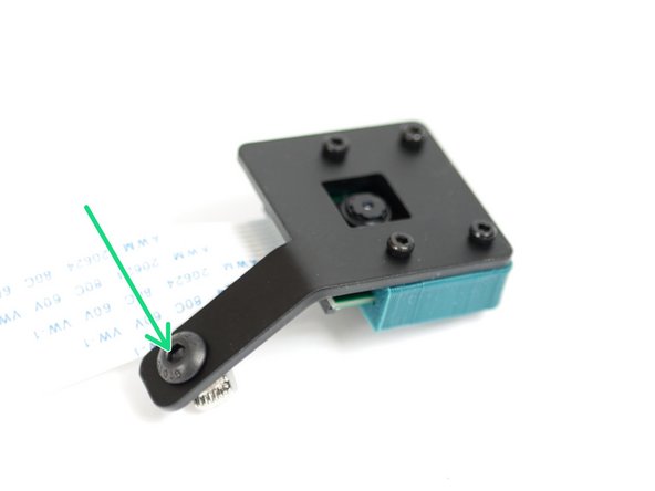
Slide the Camera into the 3D printed casing.
-
You may need to use a craft knife to cut away any excess plastic from the 3D printed part.
-
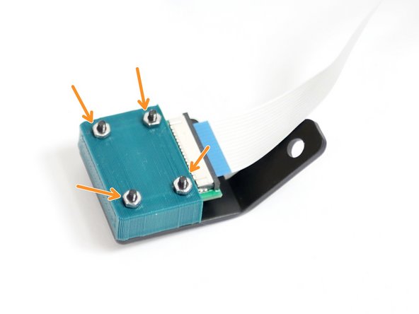
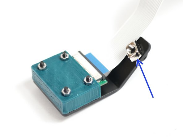
Secure the camera and the casing to the metal mounting bracket.
-
M2 x 14mm Bolt
-
M2 Nut
-
-
-
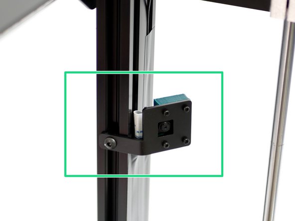
Mount the camera assembly to the frame as shown.
-
Route the cable down into the base.
-
Use electrical tape to secure the cable to the extrusion.
-
-
-
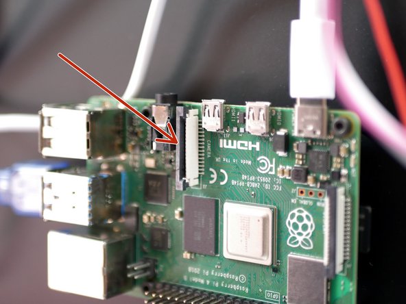
Pull up on the tab on the Pi board.
-
Slide the camera cable in as shown.
-
Push the tab back down to secure in place.
-


Cancel: I did not complete this guide.
2 other people completed this guide.
