
-
-
Before installing this upgrade you will need a Raspberry Pi board. If you don't already own one from a previous project you can purchase one relatively easily locally.
-
We also sell the Raspberry Pi (recommended) here on our webstore.
-
-
-
From Stage 1 of the main build you should have already mounted the standoffs and the Pi board.
-
M2.5 x 6mm bolt
-
M2.5 x 10mm stand-off
-
-
-
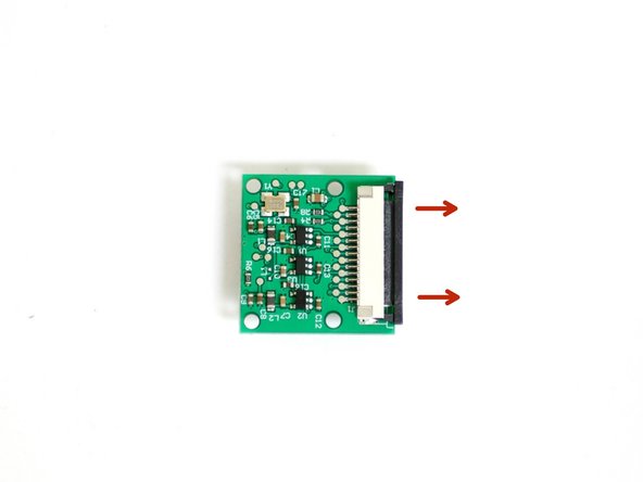
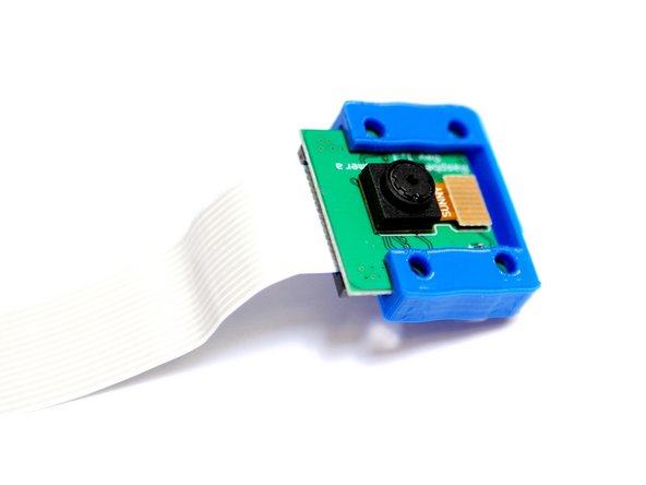
Carefully pull back the black bar on the connector on the back of the Pi camera.
-
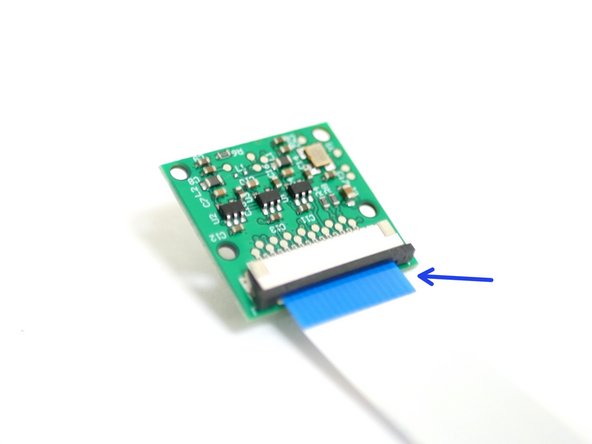
Connect the 60cm ribbon cable to the Pi Cam with the blue tab facing towards you.
-
-
-
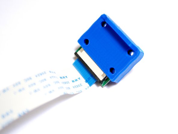
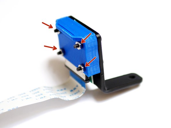
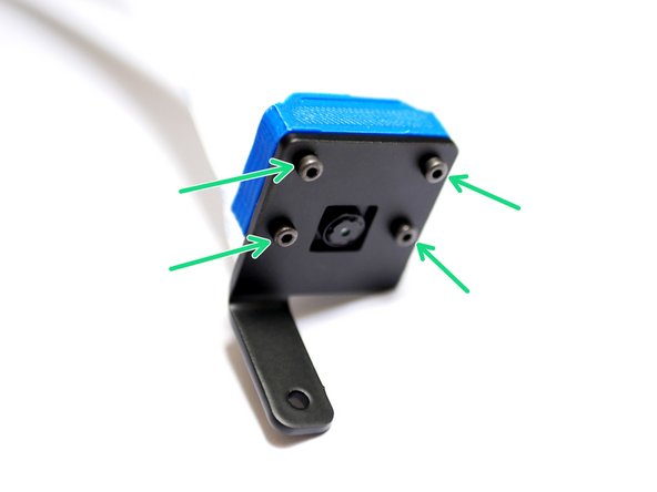
Fix the metal casing to the camera and printed case.
-
M2 x 12mm bolt
-
M2 Nut
-
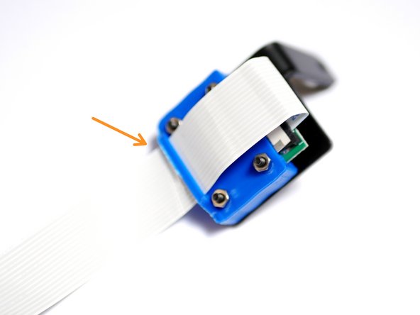
Finally feed the ribbon cable through the slot on the casing.
-
-
-
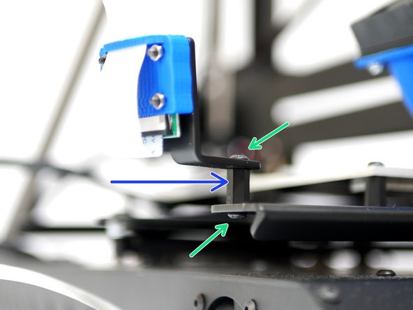
Mount the Pi Cam assembly to the bottom left of the platform.
-
M3 x 6mm bolt
-
M3x10mm stand-off
-
-
-
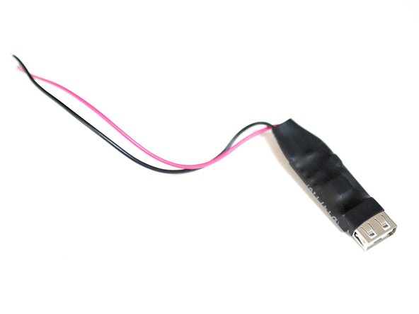
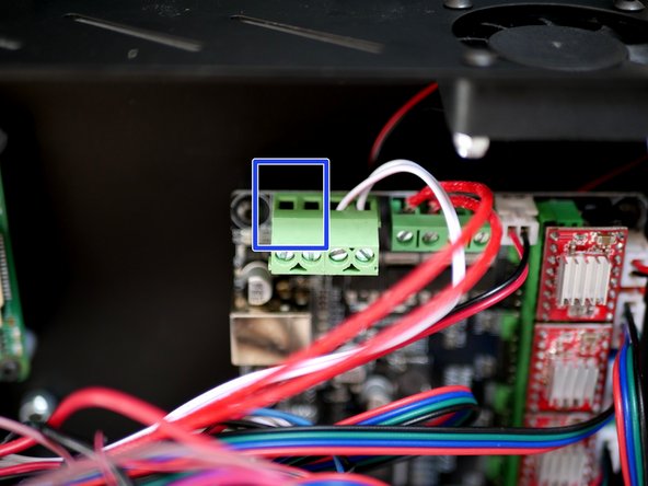
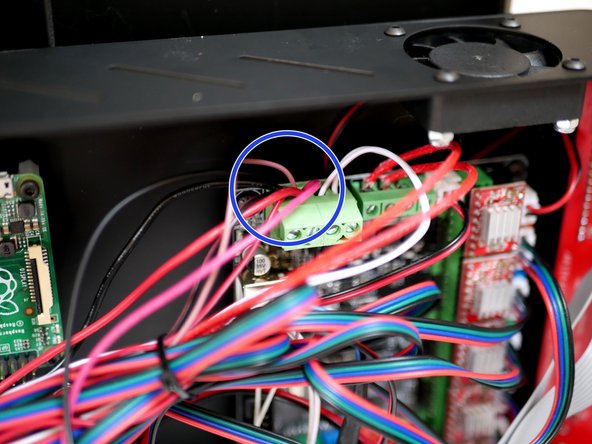
Connect the USB convertor in line with the power supply cables at the control board.
-
Make sure to connect the red cable to the positive terminal and the black cable to the negative terminal.
-
-
-
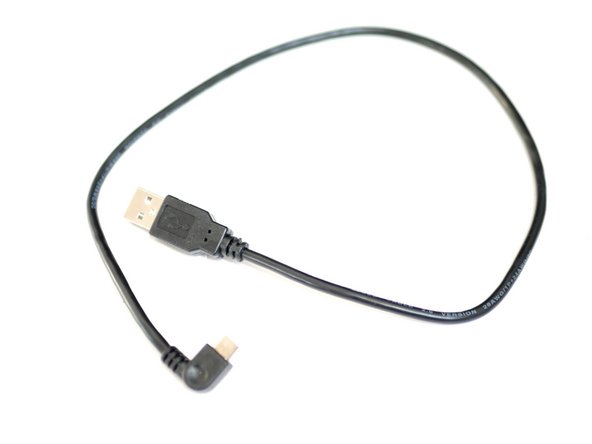
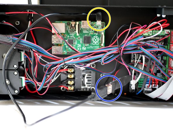
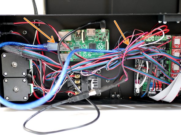
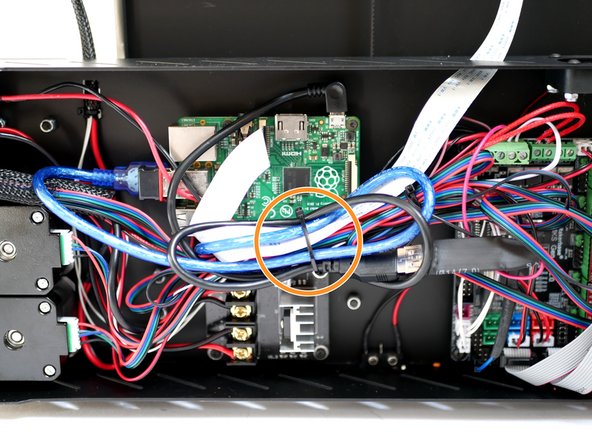
Plug one side of the micro USB cable into the Raspberry Pi.
-
Plug the other end into the convertor.
-
-
-
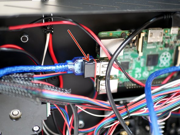
Connect the blue USB cable from the control board to a USB port on the Raspberry Pi.
-
-
-
Plug the USB Wi-Fi adapter into one of the USB ports on the Raspberry Pi.
-
-
-
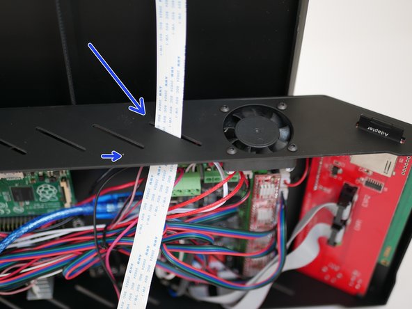
Feed the Pi Cam ribbon cable into the base through one of the slits.
-
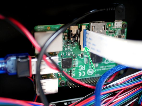
Plug the Pi Cam ribbon cable into the Raspberry Pi like shown.
-


Cancel: I did not complete this guide.
4 other people completed this guide.
