Difficulty
Moderate
Steps
25
Time Required
- Stage 01: Hotend Assembly 25 steps

In Progress
This guide is currently being written. Reload periodically to see the latest changes.
Quiz
0
-
-
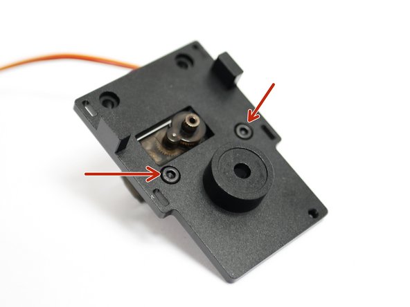
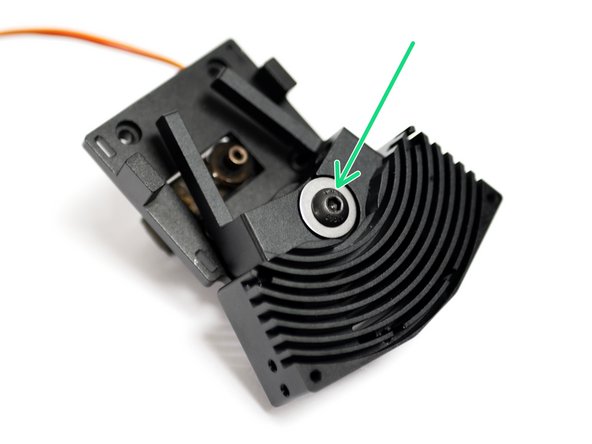
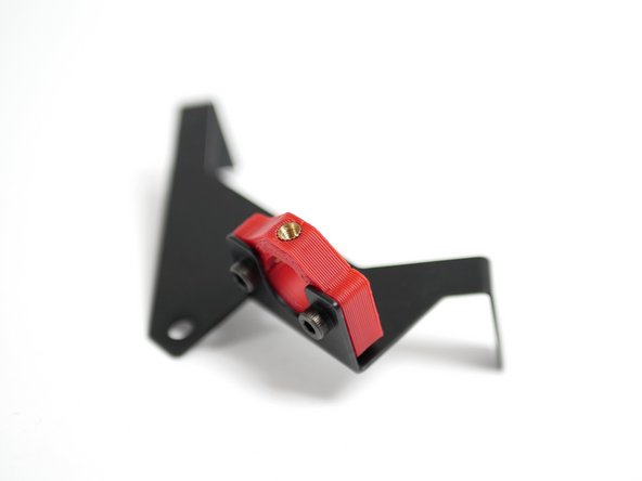
Use two M2.5 x 6mm bolts to fix the servo onto the backplate.
-
Make sure that the servo shaft is centrally aligned with the backplate.
-
-
-
Insert an M5 x 20mm bolt with a needle bearing and shim.
-
M5 x 20mm Bolt
-
Thrust Bearing
-
Shim
-
On the other side of the heatsink slide on another thrust bearing.
-
-
-
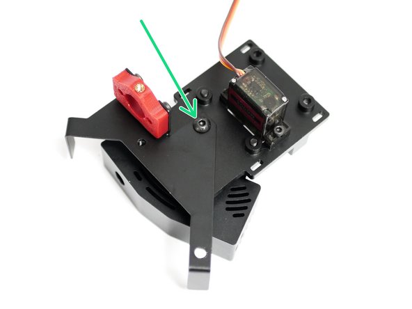
Begin by preparing the backplate with two M3 x 8mm bolts as shown.
-
Drop an M5 nut into the back of the Backplate.
-
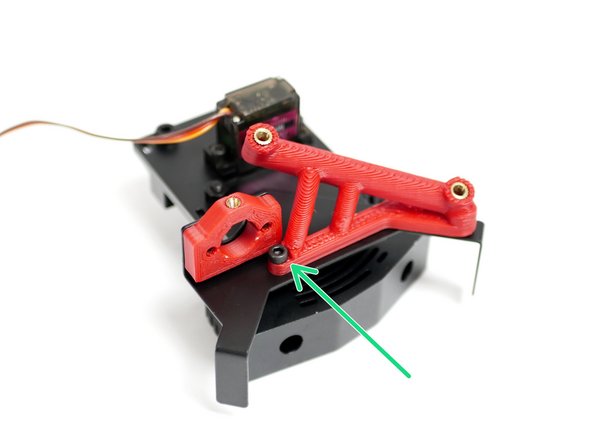
Fix the assembly together, making sure that there is no play in the switching motion.
-
The bolt should be tightened down enough to allow the heatsink to rock, but there shouldn't be any play along the axis of rotation or on the plane of contact.
-
-
-
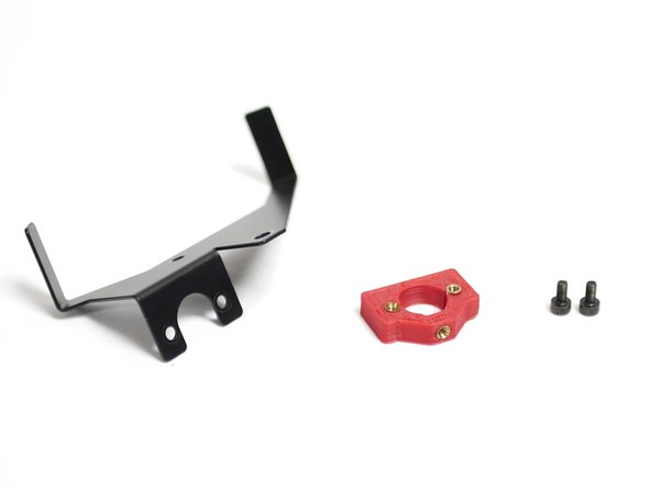
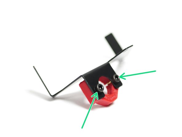
Fix the Probe mount onto the metal fan and probe mount as shown.
-
M3 x 8mm Cap
-
-
-
Fix the Probe and Fan Mount onto the backplate with just one M4 x 6mm bolt.
-
-
-
Fix the Angled Fan Mount to the Backplate with one M3 x 8mm bolt.
-
Remove the support material from under the angled fan mount before mounting.
-
On the front of the assembly, use an M4 x 6mm bolt to secure the angled fan mount.
-
-
-
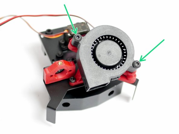
Secure the part cooling fan to the mount with two M4 x 20mm bolts.
-
-
-
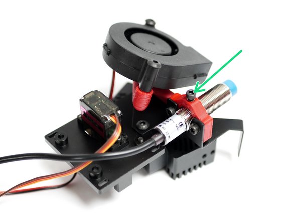
Insert the probe here and lightly secure it with an M3 x 8mm bolt.
-
We'll be adjusting the height of the probe later.
-
-
-
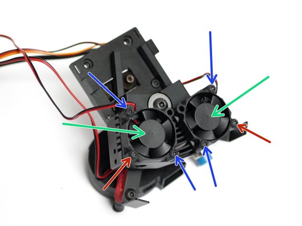
Fix the two 30mm fans to the heatsink:
-
M3 x 12mm bolt
-
M3 x 20mm bolt
-
-
-
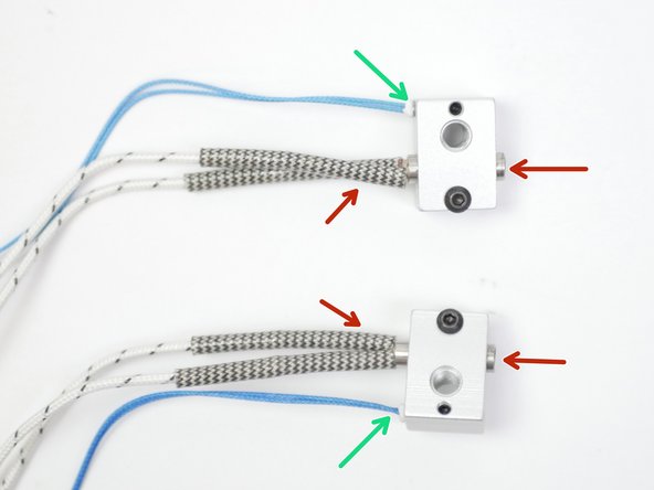
Take the two heater blocks and fix into them the two heater cartridges as shown.
-
Fix two thermistors to the blocks. We've shown two high temp. thermistors being installed here, but it is identical for the low temp thermistors too.
-
Make sure to match the orientation as shown in the photos. The two assemblies should mirror each other.
-
-
-
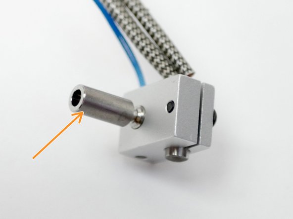
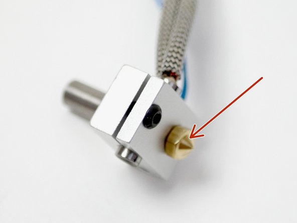
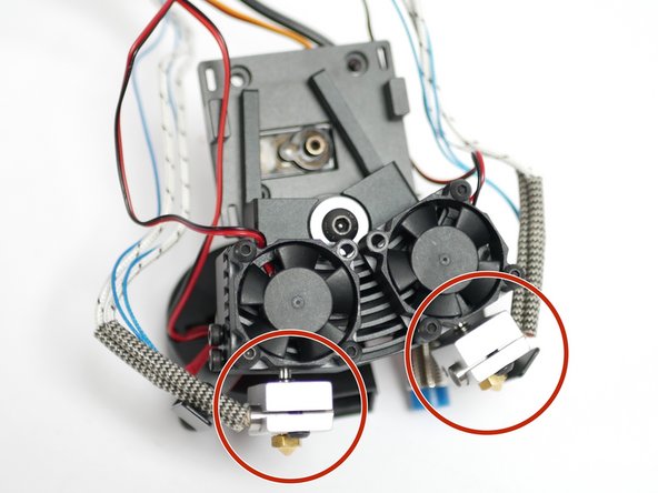
Fix onto both the heater blocks, the heatbreak.
-
and the nozzle.
-
Make sure that the nozzle is tight against the heatbreak, but leave a slight gap between the nozzle and heater block when tightening. The nozzle will need to be tightened again when hot.
-
-
-
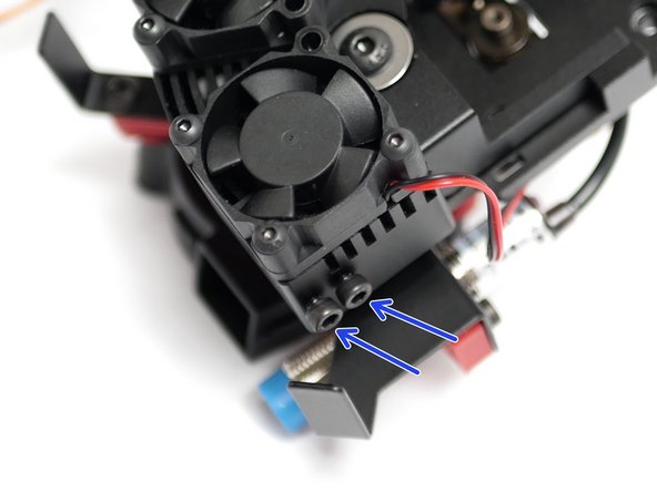
Prepare the heatsink by inserting two M3 x 12mm bolts onto each side.
-
Take the two heater block assemblies from the previous step and push them into the heatsink.
-
With the heater block assemblies pushed in all the way, tighten the bolts to secure them in place.
-
Note the orientation in the image. The heater side of the block should be facing forward.
-
-
-
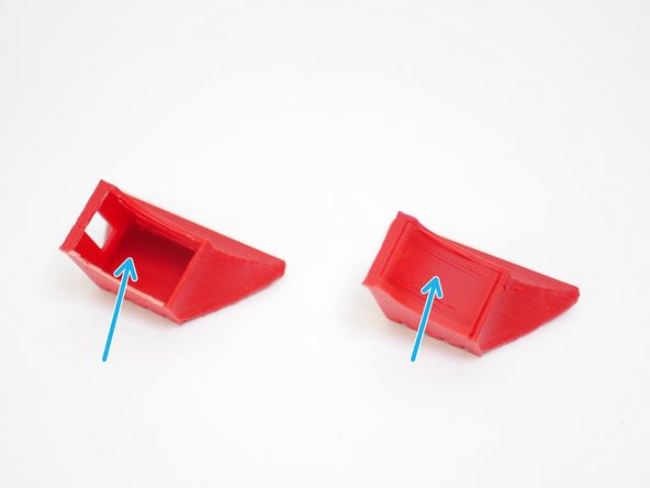
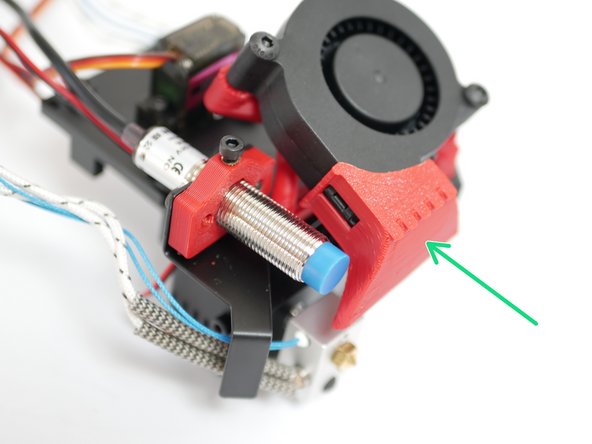
Break the support material away from the fan shroud.
-
Clip the fan shroud onto the blower fan as shown.
-
-
-
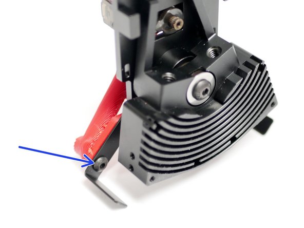
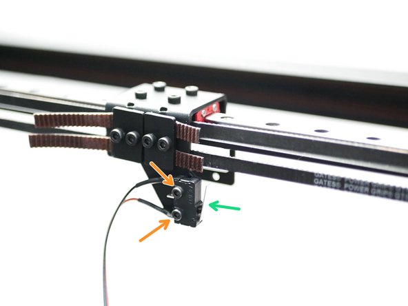
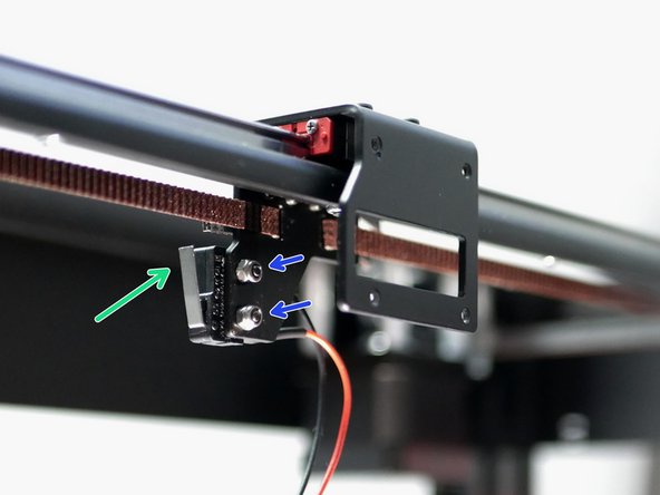
Install the X-Endstop as shown.
-
Note that the X-Endstop is the one with the longer 2M cable.
-
M2.5 x 12mm Bolt
-
M2.5 Nyloc Nut
-
-
-
Lay the DSH assembly onto the platform and arrange the cables as shown
-
Left Hotend and blower fan cables
-
Servo and Probe cables
-
Right Hotend cables
-
-
-
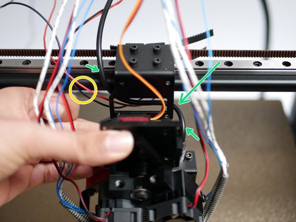
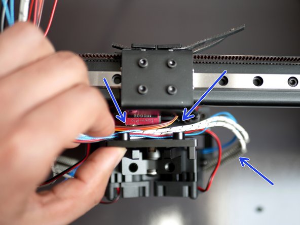
Bring the X-Endstop cable around to the front of the gantry.
-
Route the probe cable behind the tool carriage.
-
Push the servo into the hole in the tool carriage along with its cable.
-
Take the cables from the right hotend and place them over the servo.
-
-
-
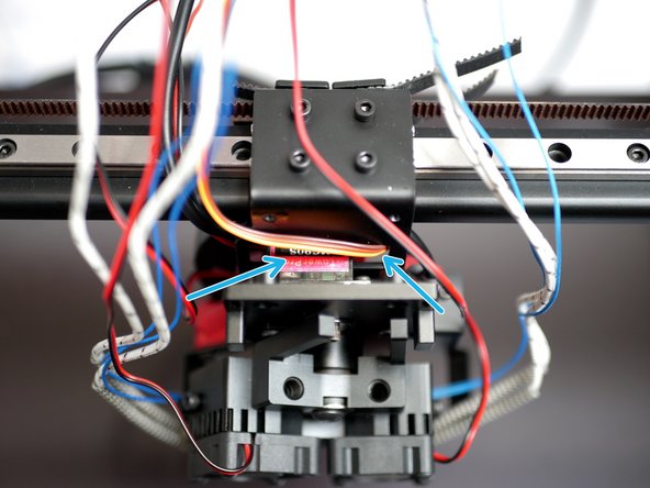
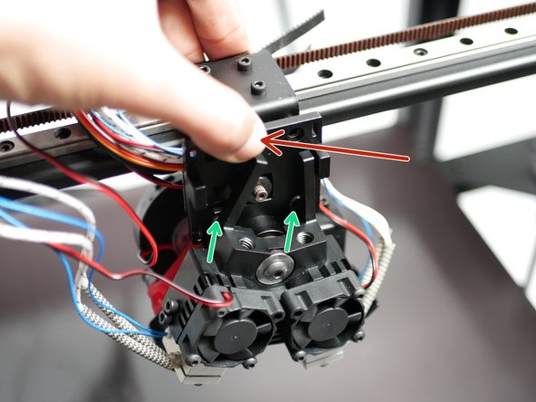
Press the DSH assembly onto the tool carriage, make sure that none of the cables are getting pinched.
-
Tighten the two M3 x 8mm bolts. Do this in alternation in order to allow the hotend to rotate out of the way.
-
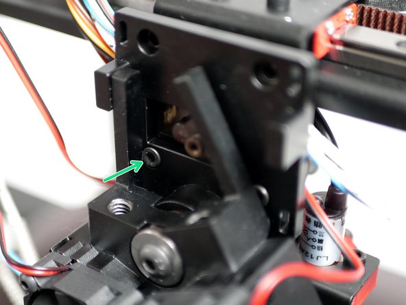
Finally, use two M3 x 8mm bolts to completely secure the DSH to the carraige.
-
-
-
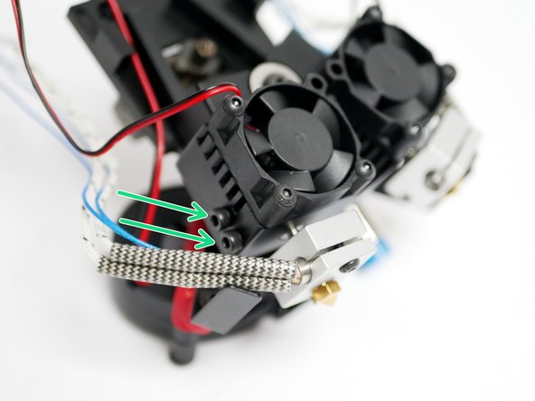
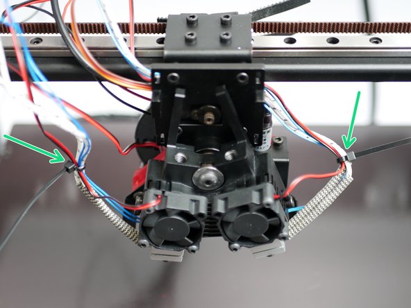
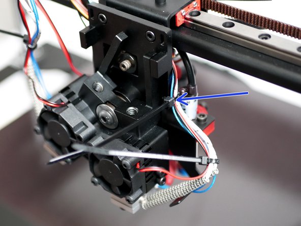
Cable tie together the heater, thermistor and 30mm fan cables from each hotend.
-
Cable tie the right hotends cables to the backplate also.
-
Ensure that when parked the highlighted part of the right hotends cables are horizontal.
-
-
-
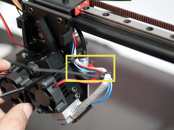
Connect the servo cable to the servo extension cable as shown.
-
-
-
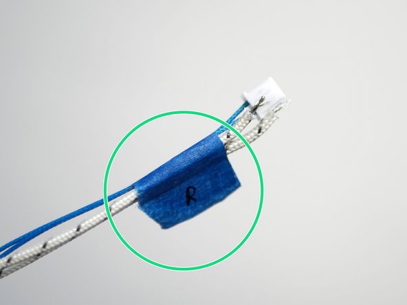
Use tape to mark, in this case, the right hotend heater cables and thermistor.
-
-
-
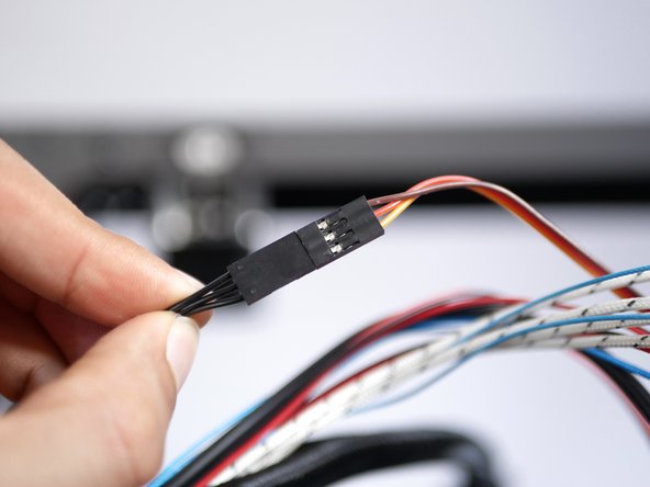
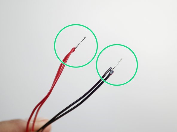
Take the hotend heatsink fan cables and use side cutters, scissors, or wire strippers to remove the connectors from their ends.
-
Strip away the outer sleeving to expose some of the wire.
-
Wrap the black and red wires together as shown.
-
-
-
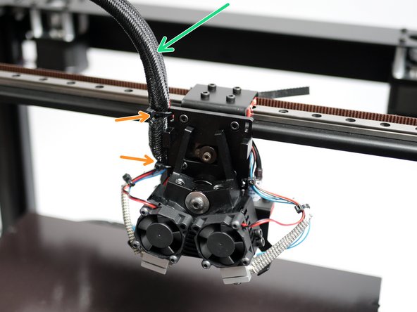
Wrap the cables with the braided cable sleeving.
-
Cable tie the cables to the backplate as shown.
-
-
-
Push the tool carraige to the bottom left of the print area.
-
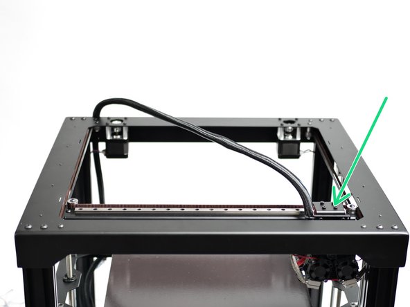
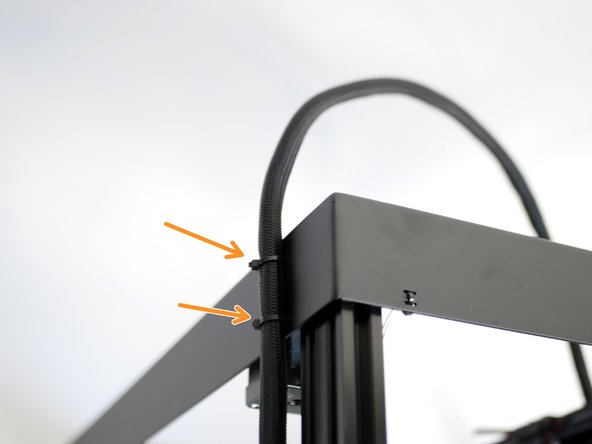
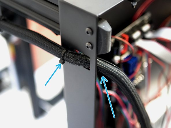
Use cable ties to secure the loom to the rear of the top panel.
-
Feed the loom of cables into the base and secure with a cable tie.
-
-
-
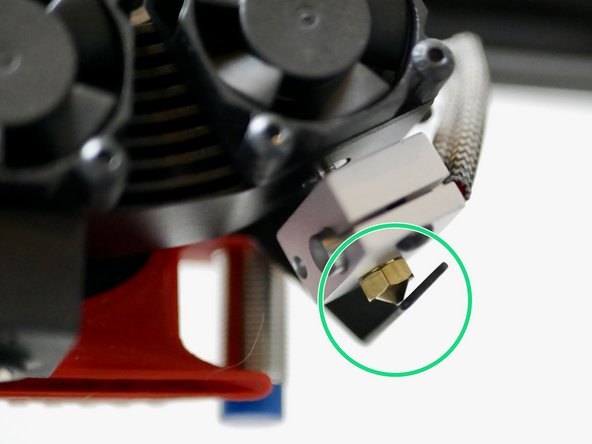
Adjust the ooze shields by bending the metal sleds until they are able to make contact with the tips of both nozzles.
-
-
-
The Hotend covers simply slide in place over the heater blocks.
-