Difficulty
Easy
Steps
8
Time Required
00:30:00 - 00:45:00
- Stage 2: Base 8 steps

In Progress
This guide is currently being written. Reload periodically to see the latest changes.

Private
This guide will not appear in search results and can only be viewed by team members!
Quiz
0
-
-
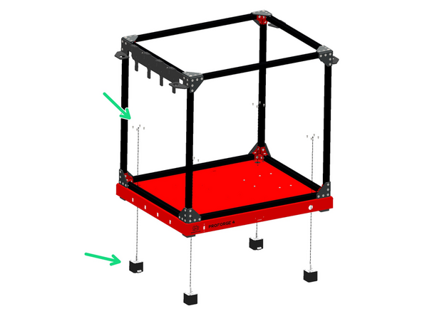
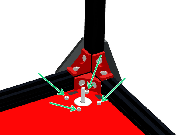
Prepare the base as shown:
-
M5 x 8mm Button
-
M5 T-nut
-
As before, do not tighten these nuts, they just need to be placed on by a few turns - they will be tightened down in the next step against the extrusions.
-
-
-
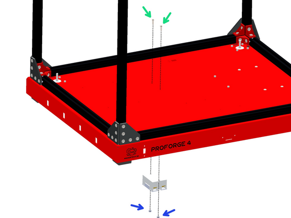
Secure the base to the bottom of the frame, orientating it as shown.
-
M6 x 75mm Bolt
-
Also add to each corner a rubber foot.
-
Align the foot so that it slots in place into the cutouts on the base.
-
-
-
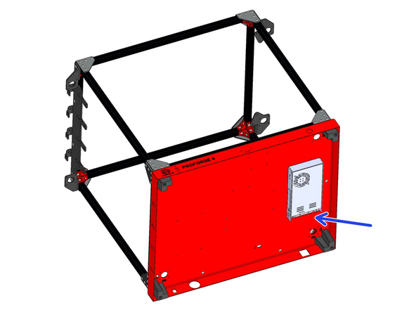
Before mounting the PSU, check that it's voltage input is adjusted correctly. The switch on the side of the unit should be set to your mains voltage. In the UK this would be 230v, in the USA it would be set 110v.
-
-
-
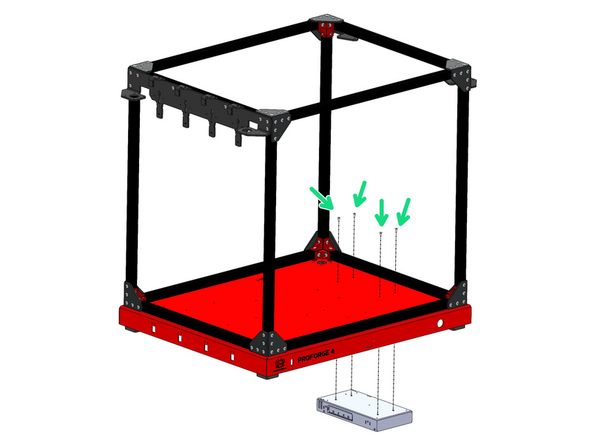
Mount the 24V PSU to the base.
-
M4 x 6mm Button Head Bolts
-
Ensure that it's mounted with its terminals pointing to the rear of the machine.
-
-
-
Before mounting the PSU, check that it's voltage input is adjusted correctly. The switch on the side of the unit should be set to your mains voltage. In the UK this would be 230v, in the USA it would be set 110v.
-
-
-
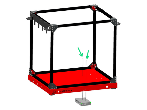
Mount the 48V PSU to the base.
-
M3 x6mm Cap Head Bolt
-
Again - ensure that it's mounted with its terminals pointing to the rear of the machine.
-
-
-
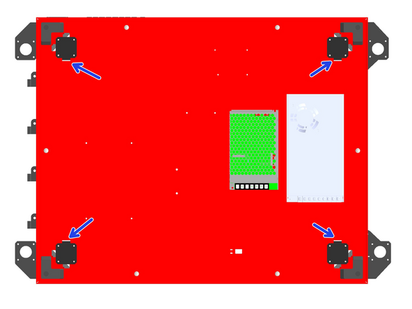
Mount the four NEMA-17 Motors to the base with M3 x 6mm cap head bolts.
-
These motors are not the high speed LDO ones.
-
Ensure that the cable connectors on the motors are all facing inwards under the base as shown.
-
-
-
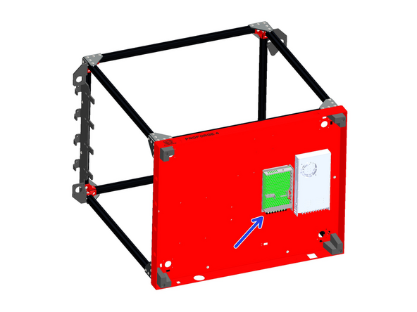
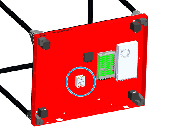
Mount the SSR Relay to the base.
-
M4 x 12mm Button
-
M4 Nyloc
-
Mount the SSR with the load side terminals facing the rear of the base.
-