
-
-
-
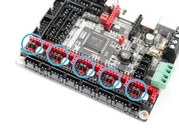
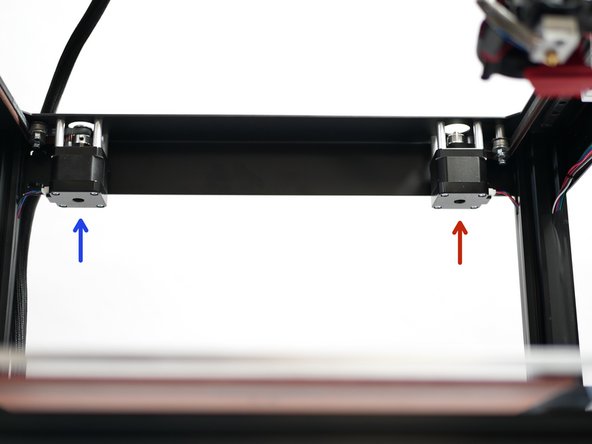
Make sure the jumpers under the steppers are positioned as shown.
-
You will need to pull the other jumpers out, so you have just one connected at each stepper location, as shown.
-
-
-
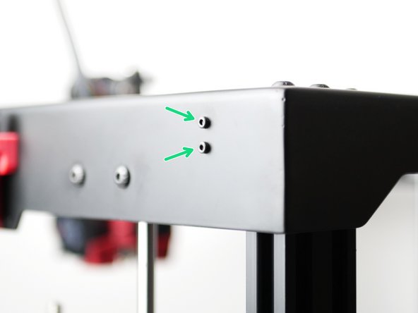
Fix the Y-Endstop to the top panel.
-
M2.5 x 12mm
-
M2.5 Nyloc
-
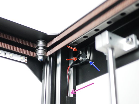
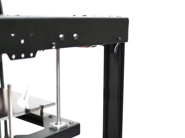
Route the cable down the 2040 extrusion.
-
Optional - Use electrical tape to better secure and hide the cable.
-
-
-
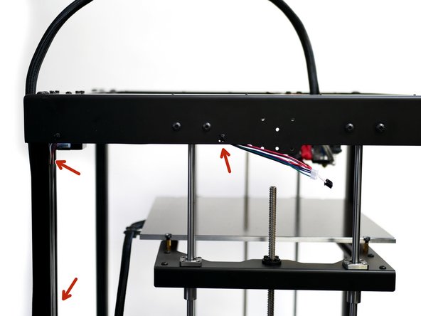
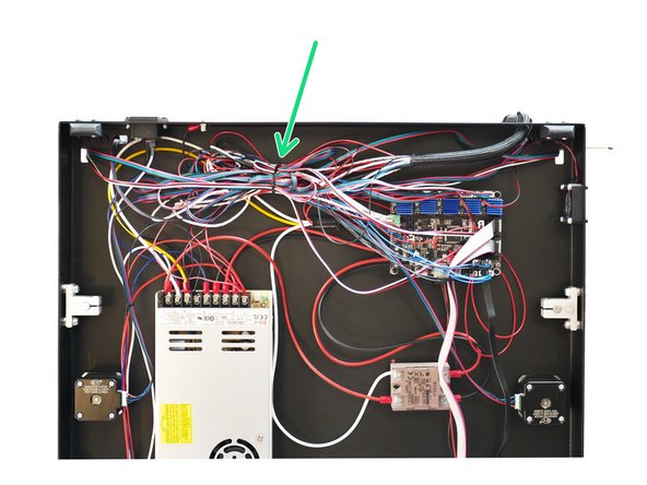
Take the filament sensor and motor cables together and fix with a cable tie to the top panel.
-
Route the cables down the 2040 extrusion as shown. Use electrical tape to cover the cables.
-
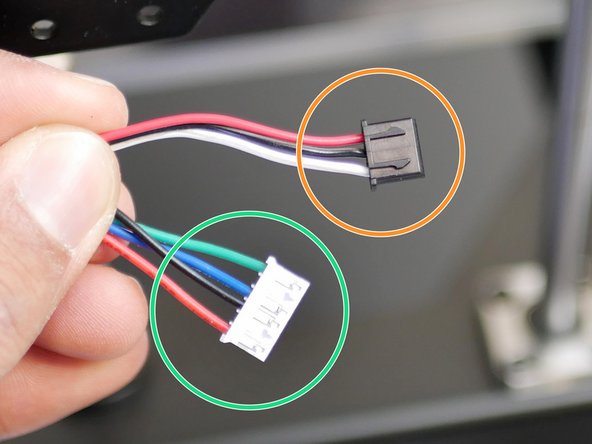
Make sure that the sides of the cable that are fixed to the top panel are those that are shown in the photo.
-
Motor cable
-
Filament sensor cable
-
-
-
Repeat the previous step, but this time on the right side of the printer.
-
-
-
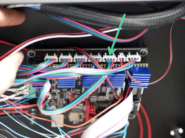
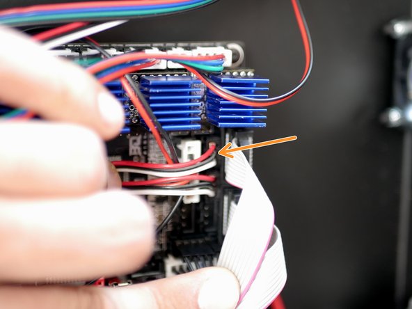
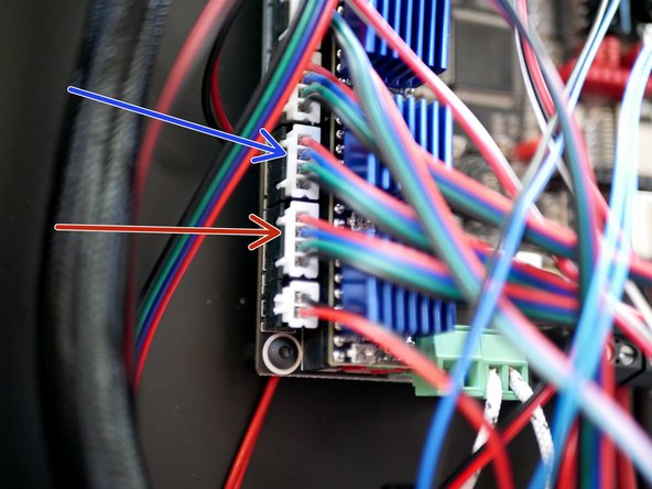
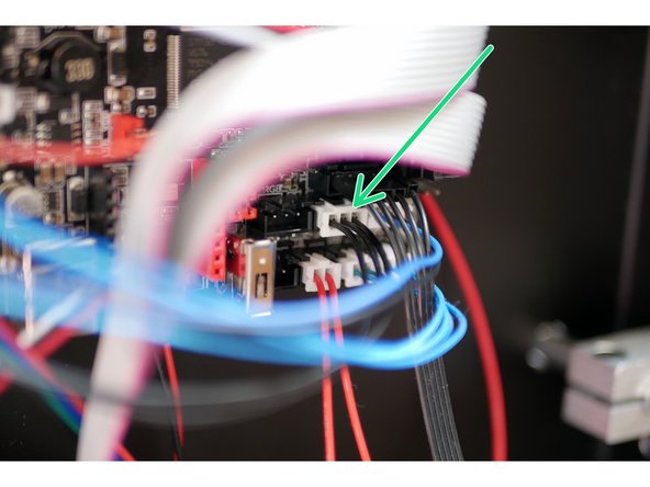
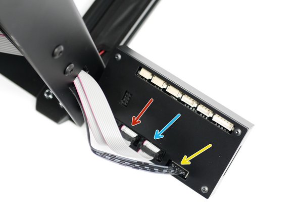
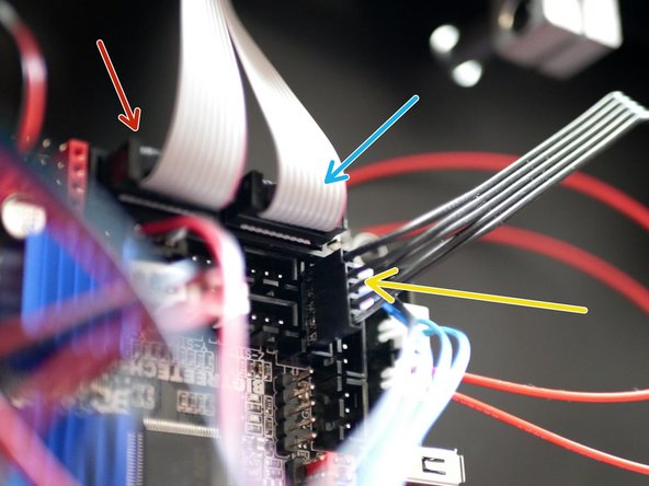
Connect the left side extruder motor cable to the control board.
-
Connect the left side extruder filament sensor to the control board.
-
-
-
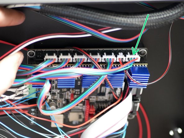
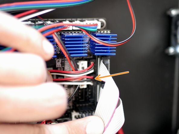
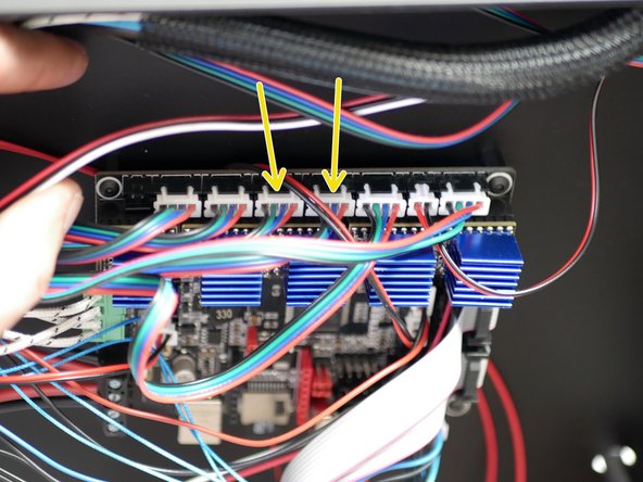
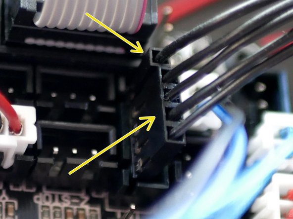
Connect the right sides motor cable to the control board.
-
Connect the right sides filament sensor to the control board.
-
-
-
Connect a motor cable to the X/Y Motors and route them down the side of the 2040 Extrusion.
-
Use electrical tape to hide and secure in place.
-
Connect the motor cables to the control board.
-
Left Motor
-
Right Motor
-
-
-
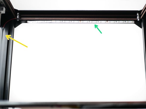
Stick the LED strip light to the inside front of the top panel.
-
Route the cable down the front right side. Again, use electrical tape to hide and hold the cable in place.
-
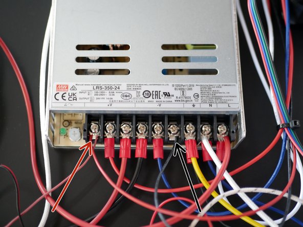
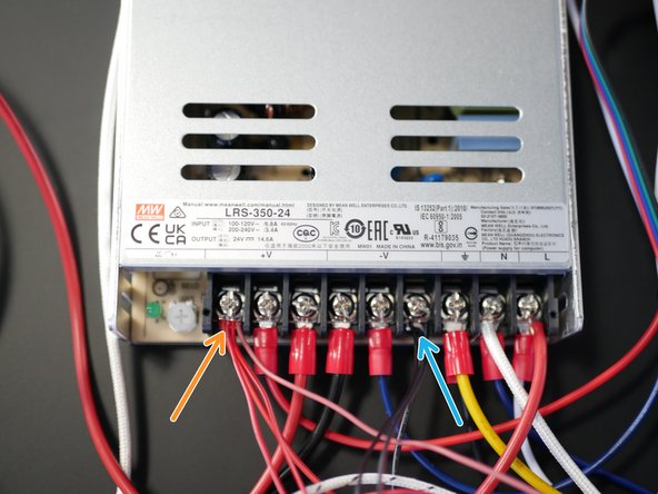
Wire the LED's directly to the power supply.
-
Red to positive
-
Black to negative
-
-
-
Connect the remaining two motor cables to the two z-axis motors.
-
Connect the other side to the control board.
-
-
-
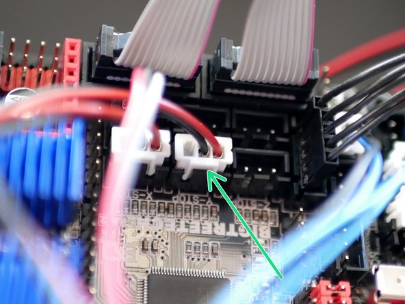
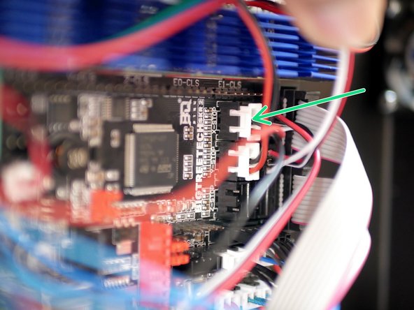
Connect the X-Endstop to the control board.
-
This is the endstop cable from the tool carriage wiring loom.
-
-
-
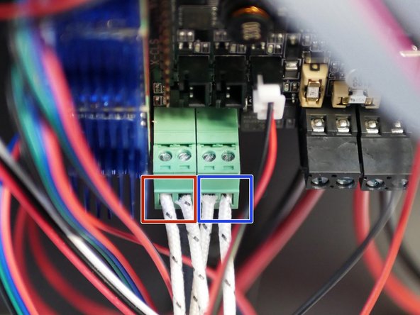
Take the left sides hotend heater and attach the cables to this connector.
-
Take the right sides hotend heater and attach the cables to this connector.
-
The connector can actually be pulled out of the board to make connecting the cables easier.
-
You will need a small flat head screw driver for this step.
-
-
-
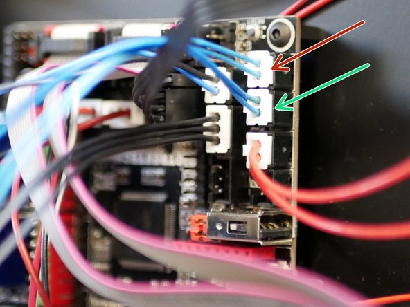
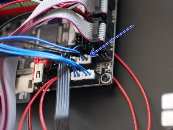
Connect the two hotend thermistors to the control board.
-
Left Hotend Thermistor
-
Right Hotend Thermistor
-
-
-
The two 30mm fans on the DSH heatsink are connected directly to the power supply.
-
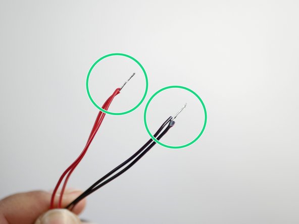
Use scissors or side cutters to remove the two connectors and expose some wire.
-
Twist the two red and black cables together as shown.
-
Connect them directly to the power supply.
-
Red to positive.
-
Black to negative.
-
-
-
Connect the brown cable from the probe directly to a positive terminal on the power supply.
-
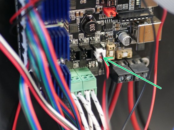
Connect the black and blue cable from the probe to the control board in the position shown.
-
-
-
Connect the servo to the control board as shown.
-
This is the servo extension cable.
-
-
-
Before beginning, make sure that you have earthed yourself (by touching a large metal object) to avoid the chances of static damage.
-
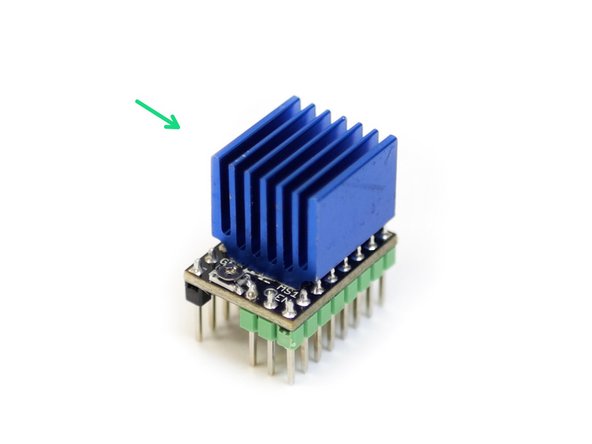
Prepare the five TMC2209 stepper drivers by removing them from their packaging and securing onto them their heat sinks as shown in the first image.
-
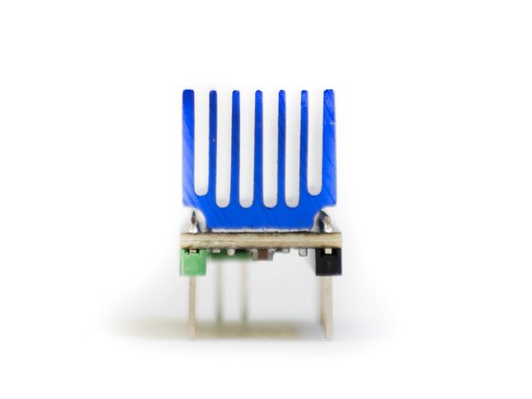
Make sure the heatsink is not touching any of the pins.
-
Orient the fins of the heatsink as shown.
-
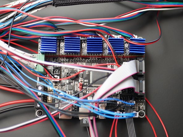
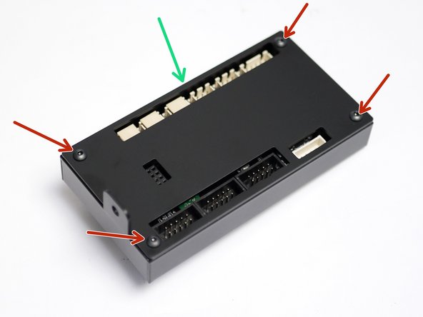
Mount all five of the TMC2209 Stepper Drivers to the control board as shown.
-
When installing, match the orientation of the drivers as shown, the green side of the stepper should go onto the red side of the mounts on the board.
-
Installing a stepper driver the wrong way round will destroy it.
-
-
-
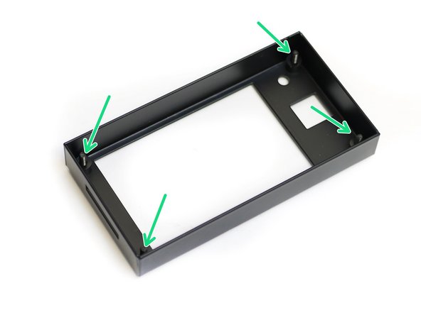
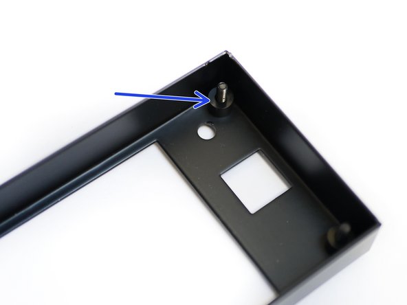
Begin by taking the touch screen case and insert four M3 x 12mm bolts through the four holes shown.
-
Place onto each of these bolts an M3 x 5mm spacer.
-
-
-
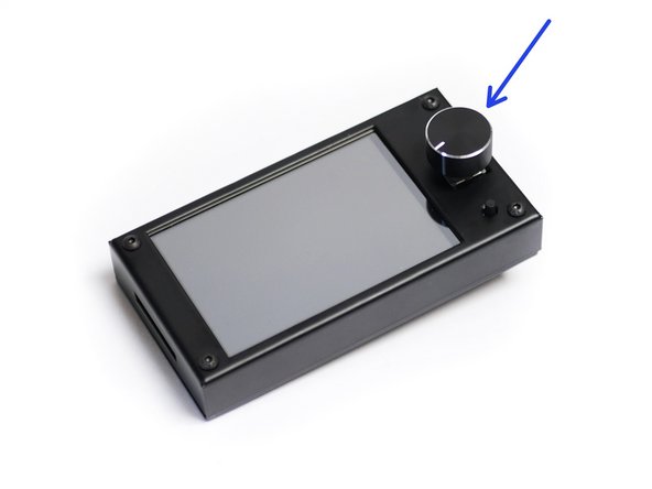
Begin by removing the black control know from the front side of the screen, it should simply pull off.
-
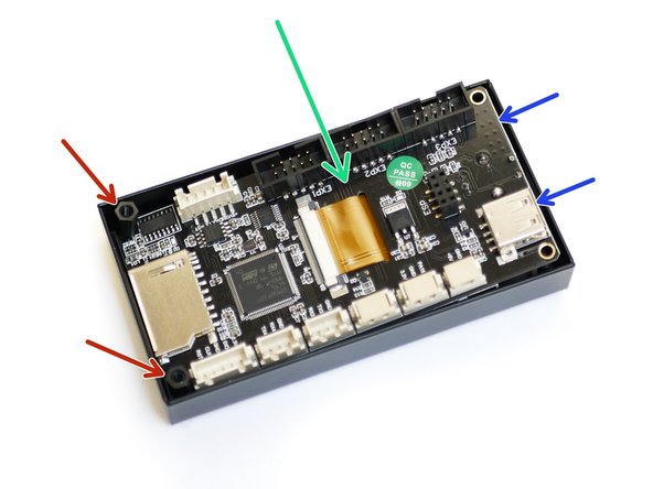
Align the touch screen with the case and drop it onto the four bolts.
-
When you drop the touch screen into the case, you'll find that the control knob side will stick up.
-
Thread on two M3 x 10mm threaded spacers to the two bolts on the left as shown.
-
-
-
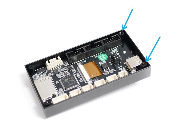
With the left side secured, thread on two M3 x 10 threaded spacers to the remaining two bolts.
-
Hold the bolts from the underneath to prevent them from falling out.
-
-
-
Fix the mounting plate onto the back of the casing as shown.
-
M3 x 6mm bolt
-
Push the control knob back back on.
-
-
-
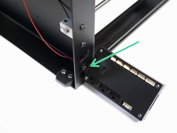
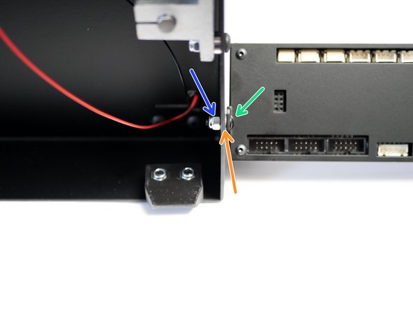
Attach the touch screen case assembly to the base of the printer as shown.
-
M4 x 10mm bolt
-
M4 Washer
-
M4 Nyloc
-
-
-
Black cable: This is for controlling the printer through the touch screen interface via serial.
-
The two white cables are for controlling the printer directly via marlin's interface through emulation mode.
-
EXP 1
-
EXP 2
-
Black cable - board side.
-
Note the orientation of the loose connector and the 4-pin connector, match as shown in the third image.
-


Cancel: I did not complete this guide.
3 other people completed this guide.
Attached Documents
