-
-
Prepare 12 rail mounts as shown by loosely fastening a T-nut onto the M5 bolt.
-
M5 x 8mm Bolt
-
M5 T-nut
-
-
-
Fix the mount assemblies from the previous steps onto the four 460mm long MGN12 rails.
-
Space them out as shown with two fixed one forth edge and the third in roughly the middle.
-
M3 x 6mm Cap Bolt
-
Use the orange stoppers to prevent the carriage from falling off the rail.
-
-
-
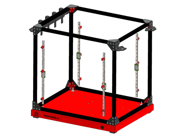
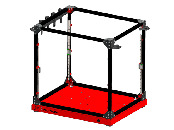
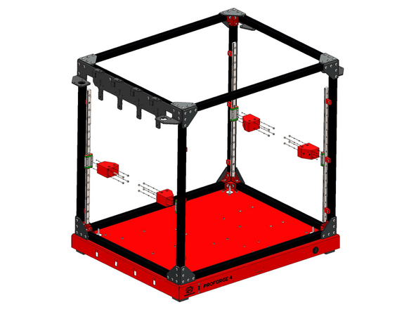
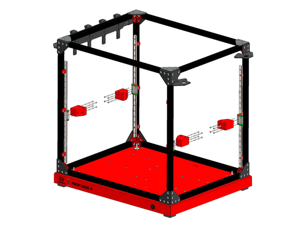
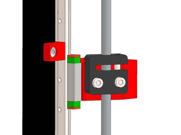
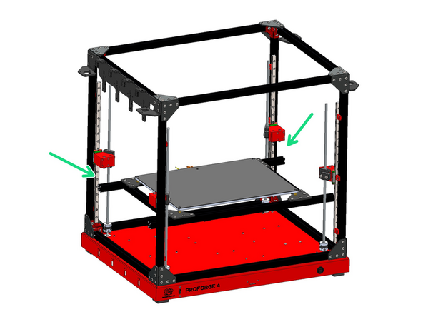
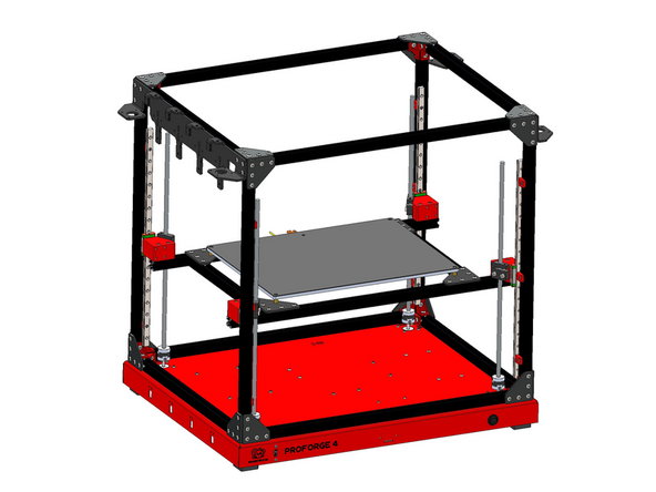
Mount the rail assemblies onto the inside of the frame as shown.
-
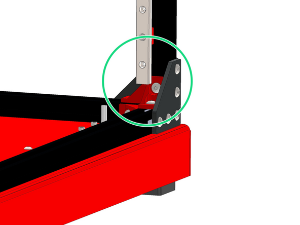
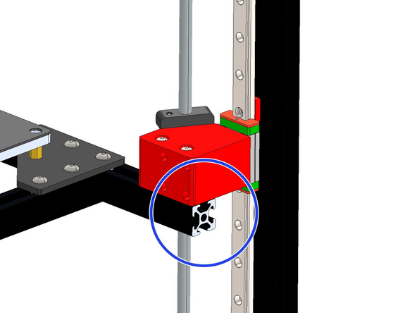
The end of the rail should fall onto the bracket near the base.
-
-
-
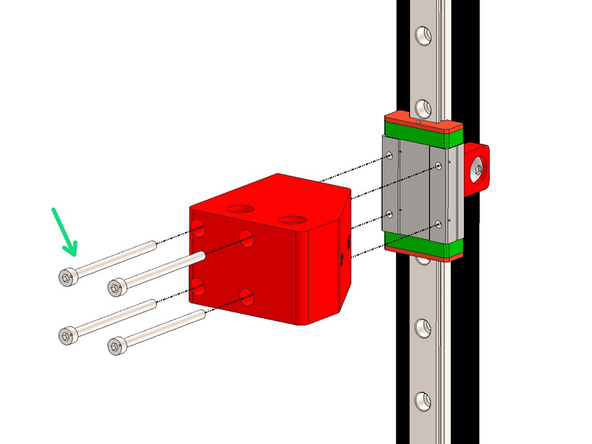
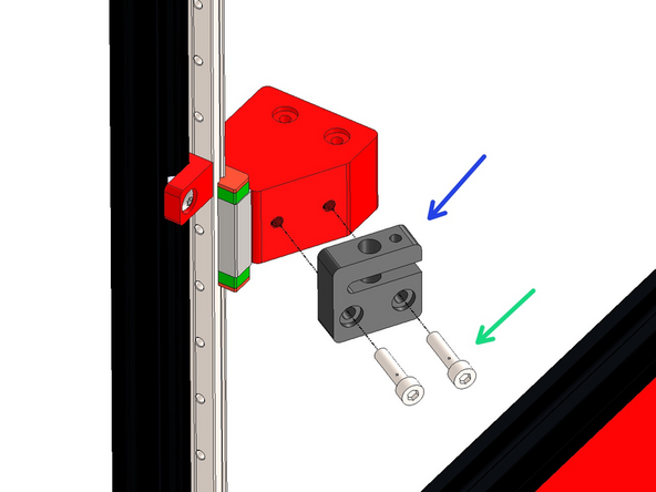
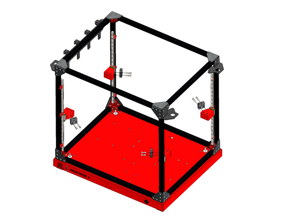
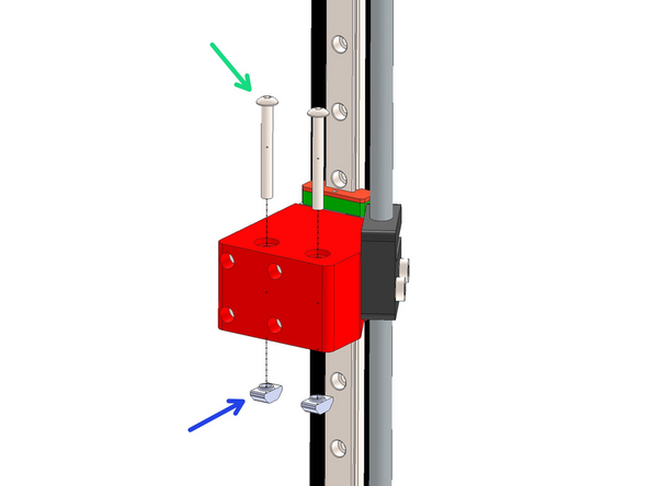
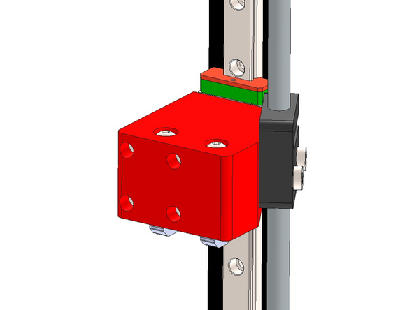
Mount Z-brackets onto the rail carriages with M3 x 45mm Cap Bolts.
-
Match the orientation of the brackets as shown in the images.
-
-
-
Fix the lead screw nut onto the bracket.
-
M5 x 20mm Bolt
-
Orientate the nut as shown.
-
-
-
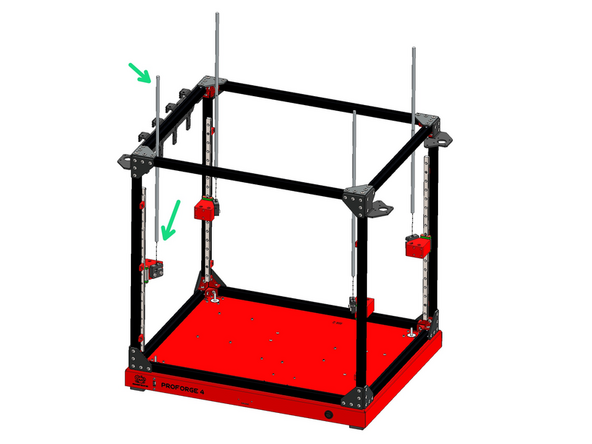
Feed the four lead screws into the nuts as shown.
-
-
-
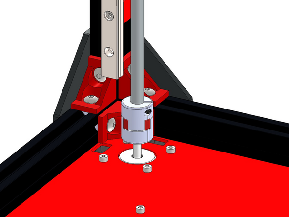
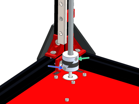
Fix the lead screws to the Z-motors with the plum couplings.
-
Tighten the bolts on the coupling to fix in place.
-
If you have the upgraded Oldham Couplings please see the next step.
-
-
-
Fix the lead screws to the Z-motors using the Oldham Couplings. They come in a bag in three pieces, the pieces can be slid on to each other to create one coupling.
-
M3 x 6mm Bolt
-
M3 x 8mm Bolt
-
There was an oversight with an initial batch of the couplings where the correct number of fasteners were not included. You will need an additional 6x M3x6mm cap head bolts and 6x M3x8mm cap head bolts.
-
You can source these locally from a hardware store, eBay or Amazon. Or complete this form here and we can send these out to you. It will take us around 3 weeks to get them delivered.
-
-
-
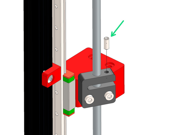
Add the M5 x 12mm Grub screw to the lead screw nut as shown.
-
Tighten until you feel some resistance, the purpose of this grub screw is to prevent backlash along the nut and lead screw.
-
-
-
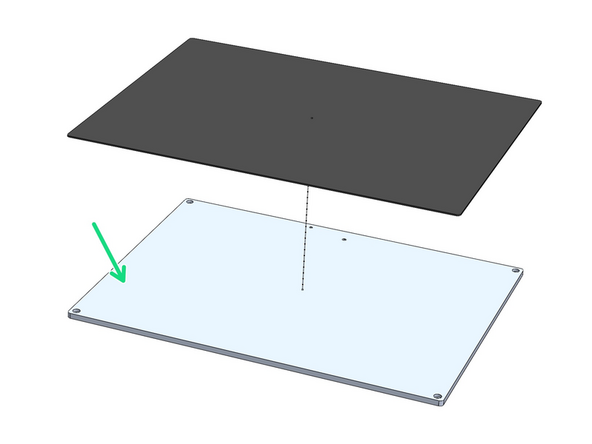
Stick over the aluminium platform plate the magnetic flex-plate sticker.
-
You may find this sticker, being magnetic, stuck onto the back of the black PEI flexplate in the packaging.
-
Ensure it is stuck onto the side shown in the images.
-
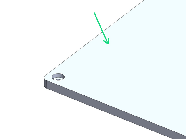
Peel away the backing paper from the magnetic sheet. Begin by sticking it to one of the shorter edges pressing it down carefully preventing any air bubbles. Use a credit card to press the sticker down, pushing out any potential air pockets.
-
After sticking the sheet down use a craft/box knife to cut away where shown to expose the holes. Use a pin to poke through the other side of the plate to make where you should cut.
-
You don't need to be particularly neat about these cuts, this sticker will have the flexplate go over it.
-
-
-
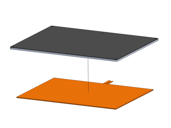
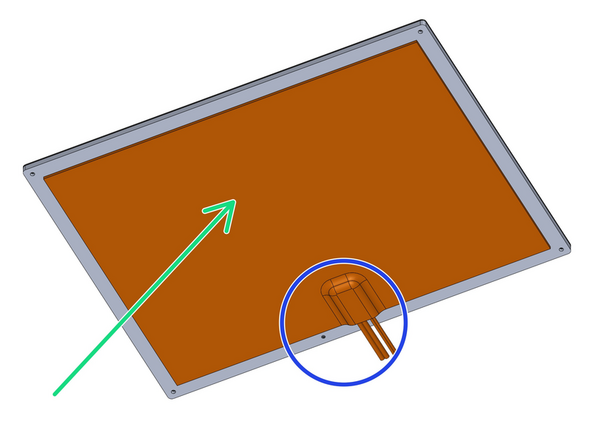
Peel the backing paper away from the heater pad.
-
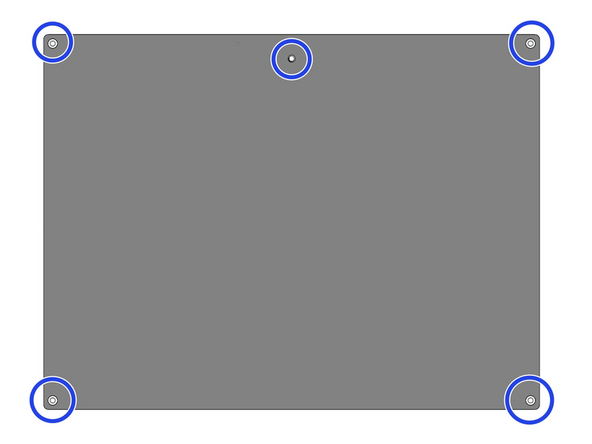
Fix the heater onto the centre of the underside of the platform as shown.
-
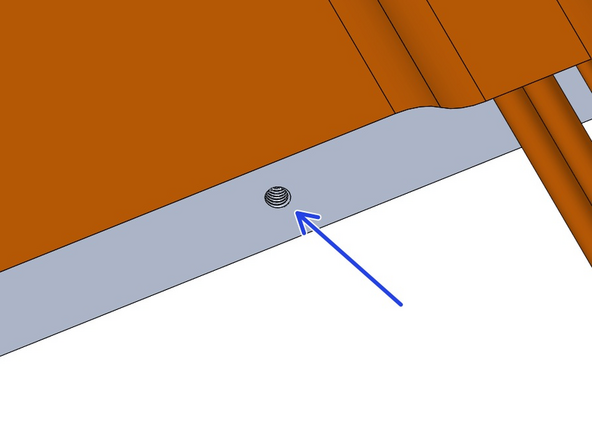
Ensure the cables are on the side with the M4 threaded hole as shown.
-
Make sure the hole is not covered either.
-
-
-
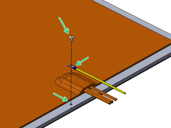
Fix the 1M Earth cable to the platform with an M4 x 6mm Bolt.
-
-
-
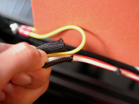
Cut 70cm of the braided sleeving and wrap the heater and earth cables with it.
-
-
-
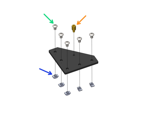
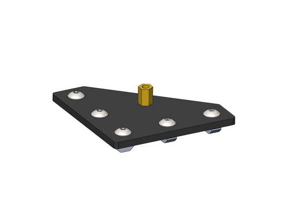
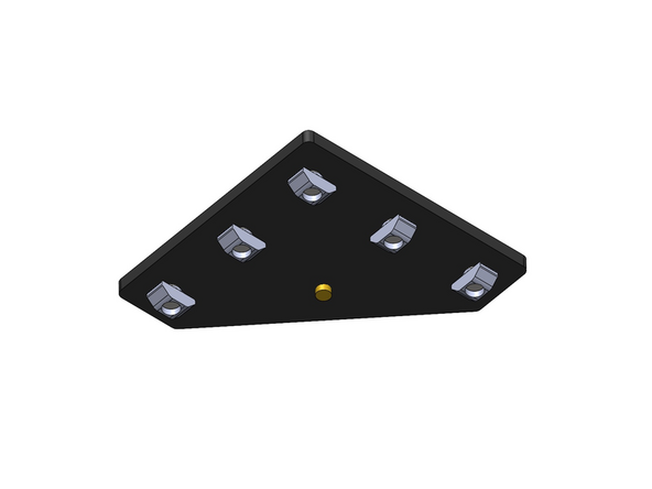
Prepare the four platform brackets as shown.
-
M5 x 8mm Button
-
M5 T-nut
-
M4 Brass Standoff
-
-
-
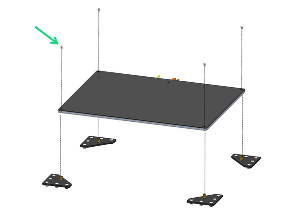
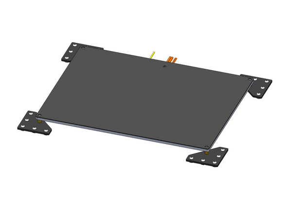
Fix the four brackets onto the platform.
-
M4 x 6mm Button
-
-
-
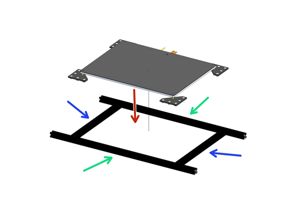
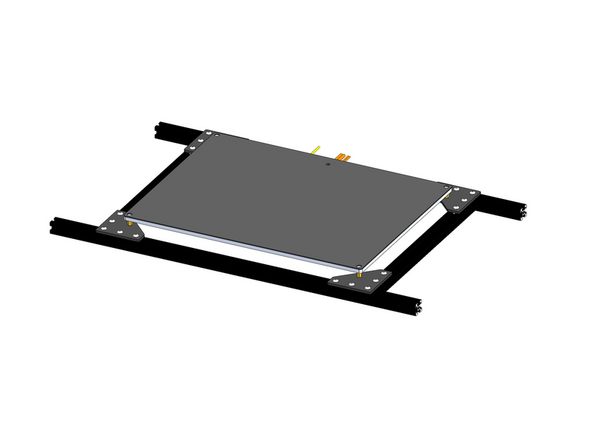
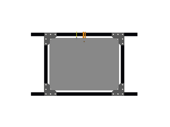
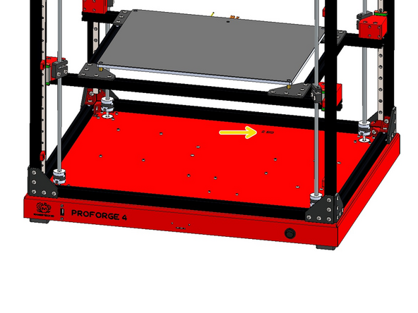
Arrange the extrusions as shown and mount the platform assembly onto them.
-
2020 Extrusion - 630mm
-
2020 Extrusion - 333mm
-
Make sure to push the cables through the centre of the frame.
-
-
-
Prepare the Z-brackets
-
M4 x 35mm Bolt
-
M4 T-nut
-
-
-
Mount the platform assembly onto the z-brackets.
-
Align the extrusions flush with the brackets.
-
-
-
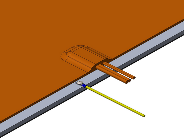
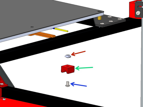
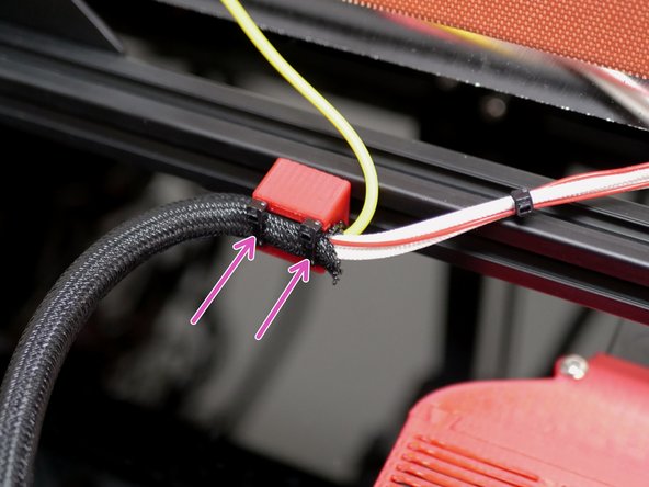
Fix the cables to the bottom of the platform frame with the 3d printed bracket.
-
M5 x 8mm Bolt
-
M5 T-Nut
-
Use cable ties to secure the heated bed cables to it as shown.
-
Route the cables into the base.
-
-
-
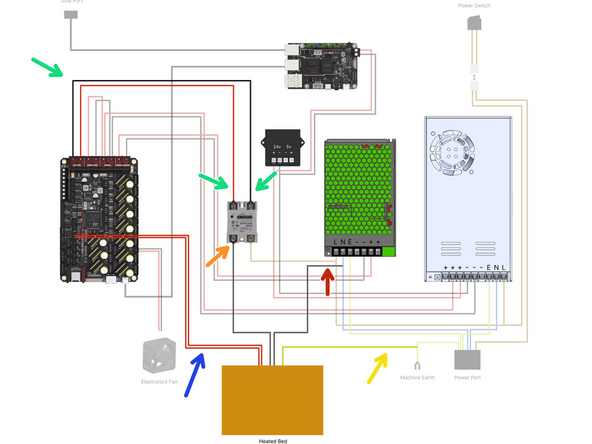
Wire the heated bed as shown:
-
Bed Signal Cables - 30cm
-
Bed Power Cables
-
One cable to SSR Relay
-
One cable to N terminal on 48v PSU
-
Bed Thermistor - Plug into control board
-
Bed Earth - Bolt to Base
-