
-
-
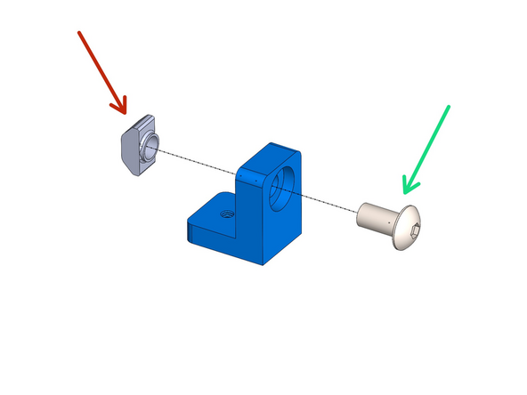
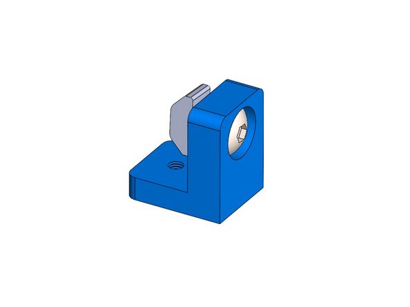
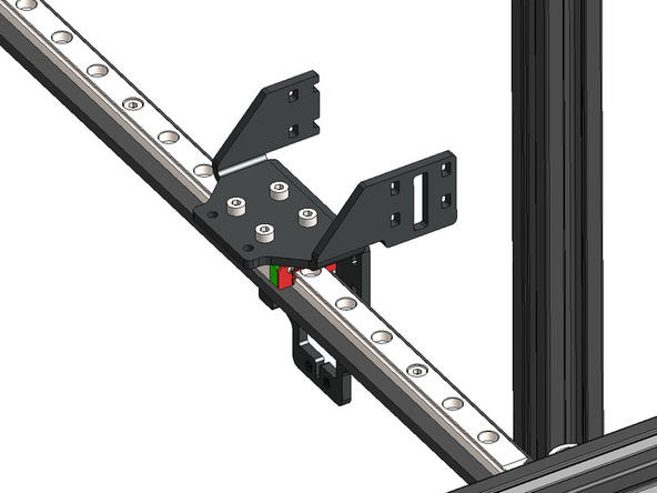
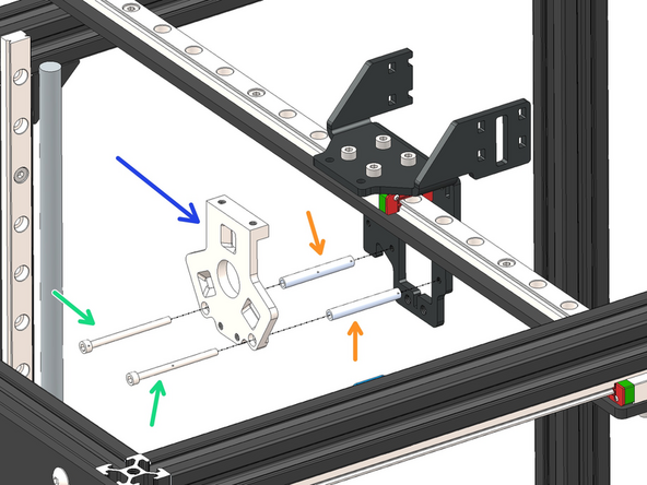
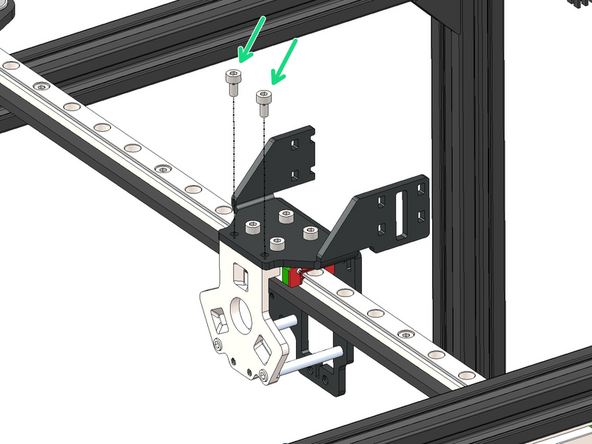
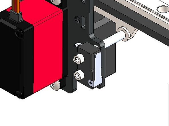
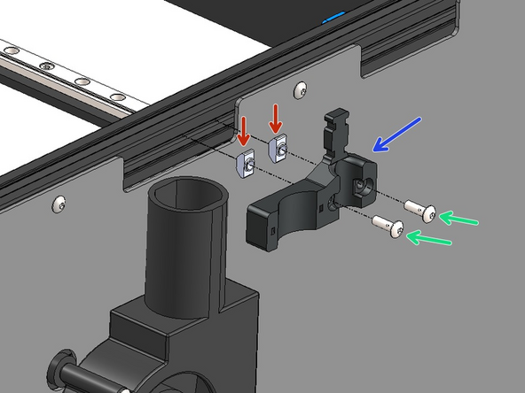
Build the X-Endstop assembly as shown:
-
X - Endstop
-
3D Printed X-Endstop Mount
-
If you find your endstop mount has oversized holes please print the updated part here if able to, or get in touch at info@makertech3d.com for a replacement.
-
M2.5 x 10mm Cap Head
-
M4 x 12mm Button Head
-
M4 T-Nut
-
-
-
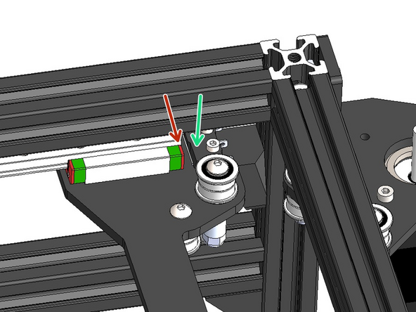
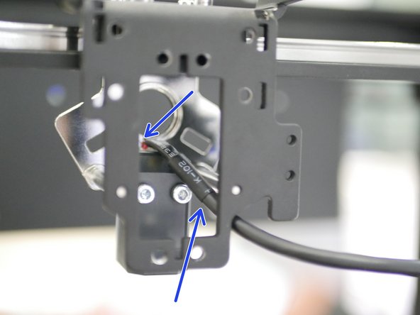
Mount the assembly to the inside rear right corner of the frame.
-
It should be fixed approximately 20mm from the top extrusion.
-
Note, the endstop is pre-wired.
-
-
-
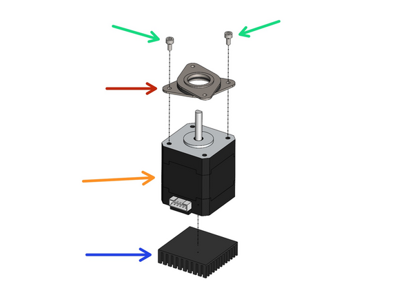
Fix onto the four LDO motors the vibration dampeners and heatsinks.
-
M3 x 6mm Cap Head
-
Vibration Dampener
-
LDO NEMA 17 Motor
-
Heatsink
-
Wipe down the base of the motor to remove any grease from the factory before sticking on the heatsink.
-
-
-
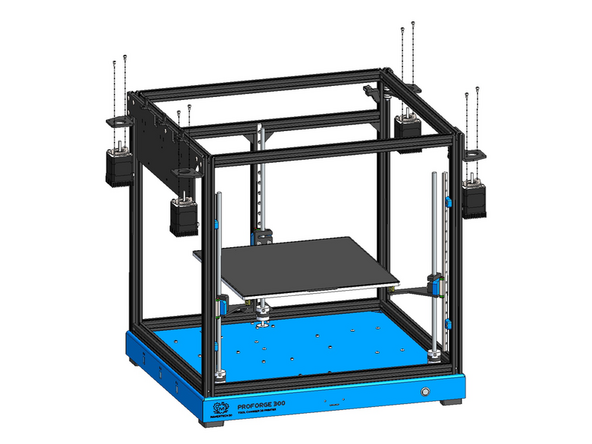
See the next step before installing the motors on the right side of the frame.
-
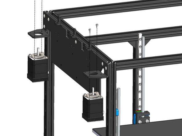
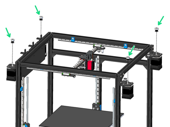
Mount the gantry motors as shown with M3 x 6mm Cap Head Bolts.
-
For easier installation of the enclosure panels we recommend pointing the motor connector ports away from the side of the printer.
-
-
-
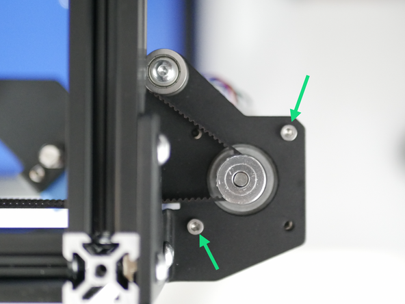
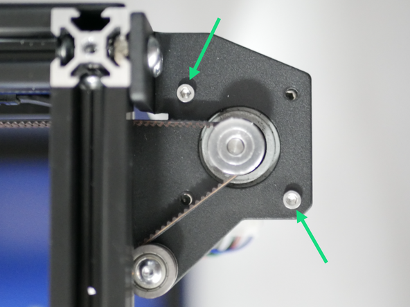
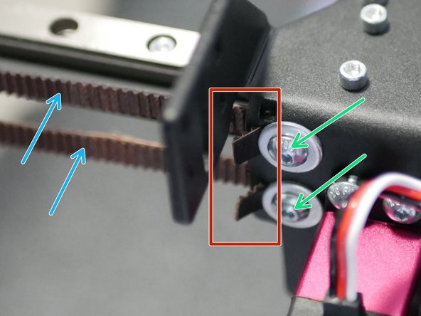
When installing the gantry motors onto the right side of the frame ensure that the bolts match as shown, if not they will rub against the belts later on.
-
-
-
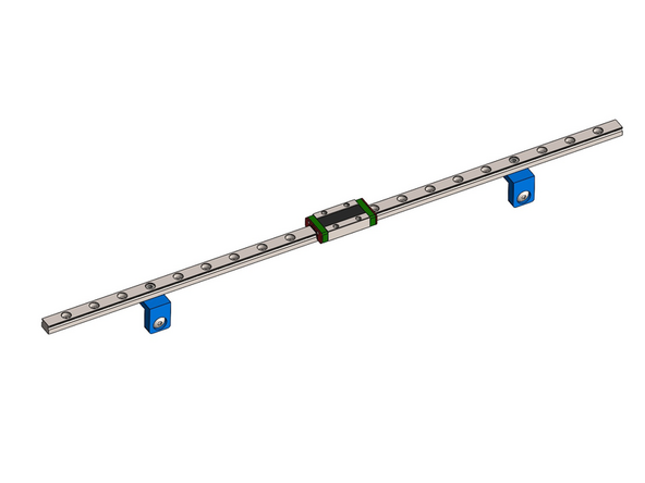
Keep the orange stoppers in place to prevent the carriage from falling off the rail.
-
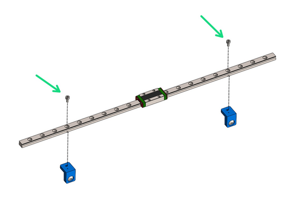
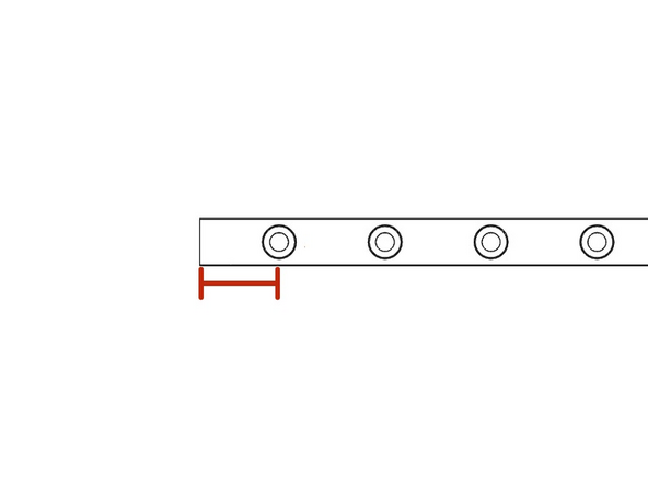
Fix the rail brackets onto the two 410mm long MGN9H rails.
-
Fix onto the fourth hole from the edge.
-
M3 x 6mm Cap Head
-
-
-
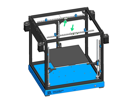
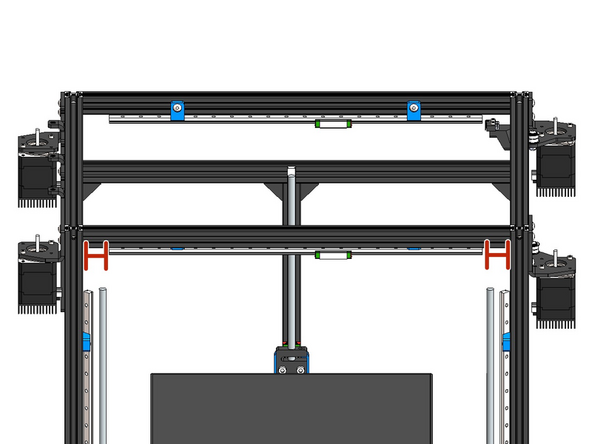
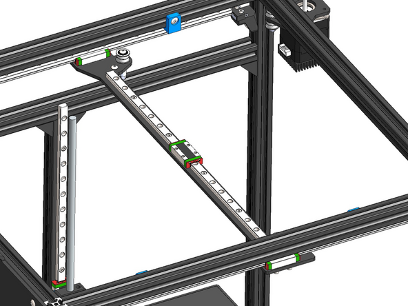
Mount the rails onto the inside of the top of the frame as shown.
-
There should be equal distance between the edges of the rails and the frame - around 30mm.
-
-
-
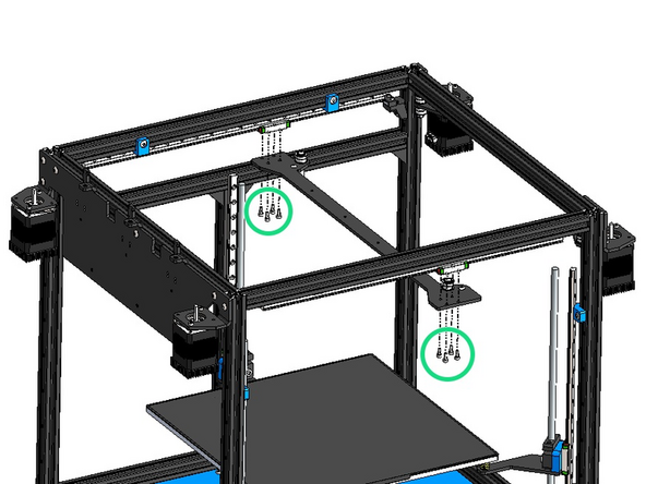
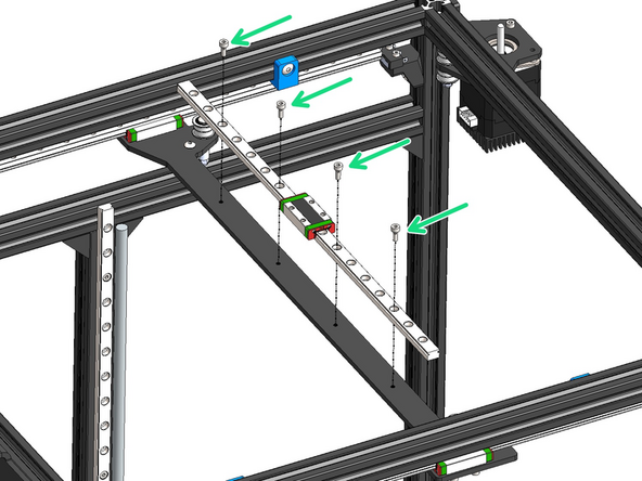
Install the gantry onto the rail carriages.
-
M3 x 8mm Cap Head
-
Fasten all bolts loosely before tightening, this will make installing easier.
-
-
-
When the gantry is slid all the way to the right it should bump the endstop as shown.
-
Remove the orange stoppers to achieve this.
-
The rail carriage should be on the edge of the rail, but should not fall off.
-
Make adjustments to the rail and/or endstop mount accordingly if the above conditions are not met.
-
-
-
Mount the final 350mm MGN9H gantry rail onto the gantry.
-
M3 x 8mm Cap Head Bolt
-
The rail should have its mounting holes start 15mm from both ends.
-
-
-
Mount the tool carriage onto the gantry rail.
-
M3 x 6mm Cap Head Bolt
-
Front of machine.
-
-
-
Take extra care when tightening to not strip the aluminium threads on the carriage.
-
Fix the Master Plate onto the Tool Carriage.
-
Master Plate
-
M2.5 x 35mm Cap Head (Do not over tighten)
-
M2.5 x 30mm Spacer
-
-
-
If you end up stripping the threads in the previous step replace the bolt with a longer M2.5 x 40mm one and secure it with a nyloc nut.
-
If you aren't able to source the longer bolt and nut locally, please drop us an email at info@makertech3d.com and we'll ship a set out to you (ETA is around 5-7 working days).
-
-
-
Start by plugging the USB cable (from the Eddy box) into the top of the Eddy Probe. The cable should route under the spacer.
-
Fix the Probe to the Master Plate with two M3 x 18mm Cap Head Bolts.
-
-
-
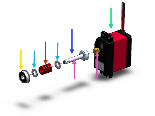
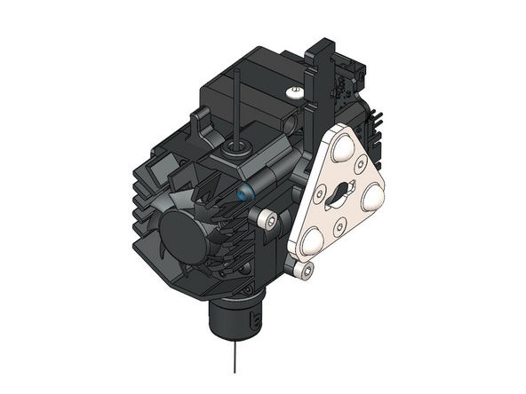
Assemble the Servo mechanism as shown.
-
Apply grease to both cam shafts.
-
Makertech Servo Motor
-
Servo Cam Shaft v2
-
M5 x 8 x 0.5mm Shim
-
Red Compression Spring
-
F605ZZ Bearing
-
-
-
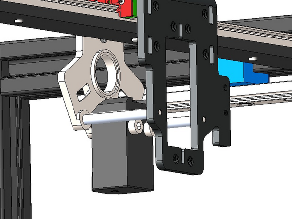
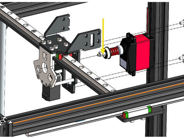
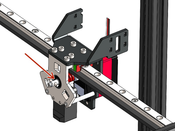
Install the servo mechanism that you built in the previous step onto the Tool Carriage.
-
Cam pin installed in next step.
-
Feed it in from behind, ensuring the bearing sits inside the hole on the Master Plate.
-
M4 x 6mm Button Head Bolt
-
-
-
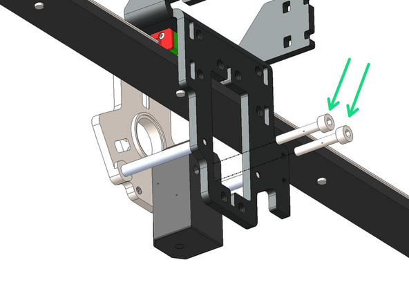
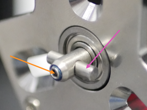
Install the cam pin with the grub screw pressing onto the flat face of the cam pin.
-
Use the included bottle of thread locker to ensure the grub screw does not come loose.
-
Cam Pin
-
M3 x 4mm Grub Screw
-
-
-
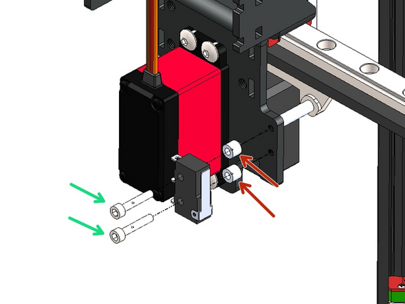
Fix the endstop to the Tool Carriage bracket as shown.
-
M2.5 x 14mm Cap Head Bolt
-
M2.5 x 4mm Spacer
-
-
-
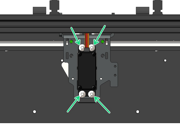
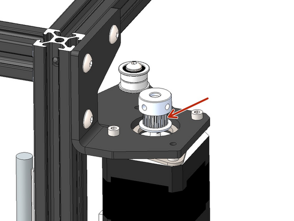
Drop pulleys onto each of the four motors.
-
Orientate so that the pulley teeth are facing downwards.
-
-
-
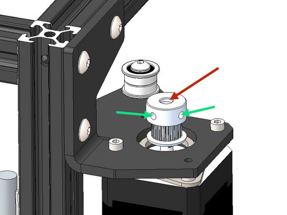
The ideal position for all of the pulleys should be approx 1-2mm above the end of the motor's shaft. You can align them later after installing the belts.
-
Ensure that one of the set screws is tightened against the flat of the motor shaft.
-
-
-
Take the 4m roll of GT2 belt and cut approximately it in half.
-
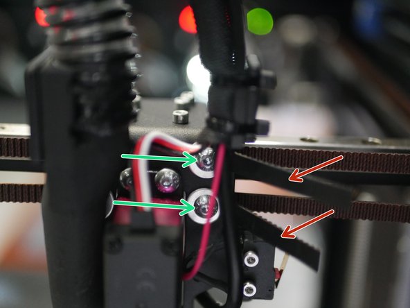
Take one end of each belt and feed it in through the slit on the back left side of the carriage bracket.
-
It needs to be fed in from the inside of the bracket - you might need to temporarily remove the bracket from the rail carriage to gain better access.
-
Ensure that the belts teeth are facing out.
-
Fix the belt in place with an M4 x 6mm button head bolt and M4 penny washer.
-
-
-
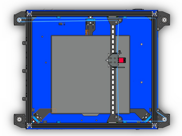
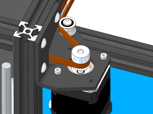
The lower belt should follow this path around the idlers and motors.
-
Remember this is the lower belt and should be wrapped around the lower level idlers.
-
-
-
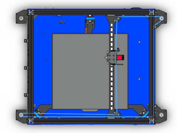
The top belt should follow this path around the idlers and motors.
-
Remember this is the top belt and should be wrapped around the top level idlers.
-
-
-
Adjust these bolts so you are able to pull the belts but also hold the tension without letting the belts slip back.
-
Pull the belts tight until there isn't any slack.
-
Next adjust the tension in the belts individually until the gantry sits straight. Use the left side of the frame as a reference.
-
Avoid over tensioning as this can result in greater vibrations and put unnecessary strain on the motor shafts.
-
Trim any excess, leaving approx. an inch free for any future adjustments.
-
-
-
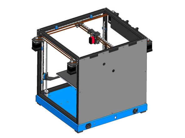
With the belts tensioned manually move the tool carriage around to ensure that motion is smooth and that the belts are not catching on anything.
-
-
-
If you have the enclosure upgrade we recommend installing the rear panel now.
-
Rear Enclosure Panel (Glossy side out)
-
M4 x 8mm Button Head Bolt
-
M4 T-Nut
-
-
-
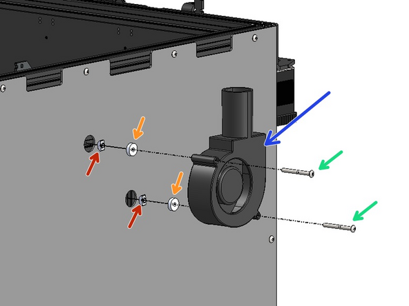
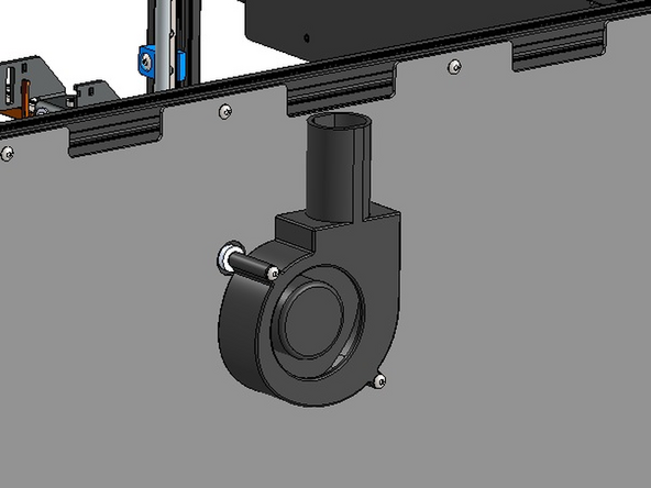
Fix the 9733 part cooling fan to the rear of the frame.
-
9733 Part Cooling Fan
-
M4 x 40mm Button Head bolt
-
M4 x 4mm Spacer
-
M4 T-Nut
-
-
-
Fix to the rear of the frame the 3D Printed cable relief bracket.
-
3D Printed Cable relief Bracket
-
M4 x 12mm Button Head Bolt
-
M4 T-Nut
-
Ensure it lines up with the fan opening.
-
-
-
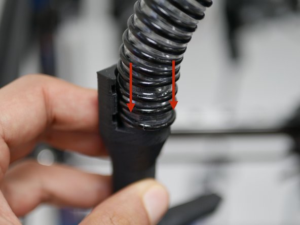
Check the length of your CPAP tube, it should be 60cm long from the end of the silicone rubber side.
-
If not, use a pair of scissors to cut the open side of the tube to achieve this.
-
-
-
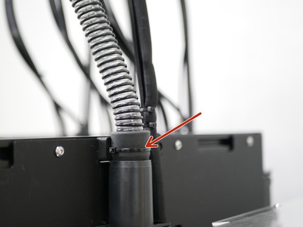
Fix the silicone side of the CPAP cooling hose to the Fan.
-
Secure it in place with a cable tie.
-
-
-
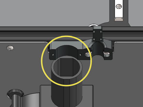
Slide the cut side of the hose onto the fan shroud.
-
Fix the fan shroud with the pipe onto the carriage using two cable ties as shown.
-
-
-
Fix to the servo the extension cable.
-
Wrap all of the cables coming from the Tool Carriage into the remaining length of the braided cable sleeving.
-
The cables should include: The Eddy USB cable, the Endstop cable and the Servo cable.
-
-
-
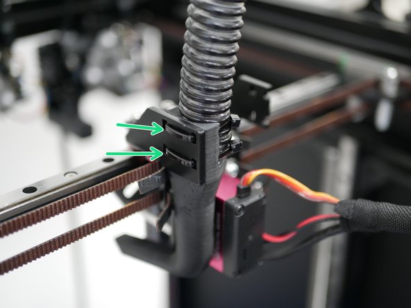
Fix the cables to the nylon cable support guide as shown using cable ties.
-
-
-
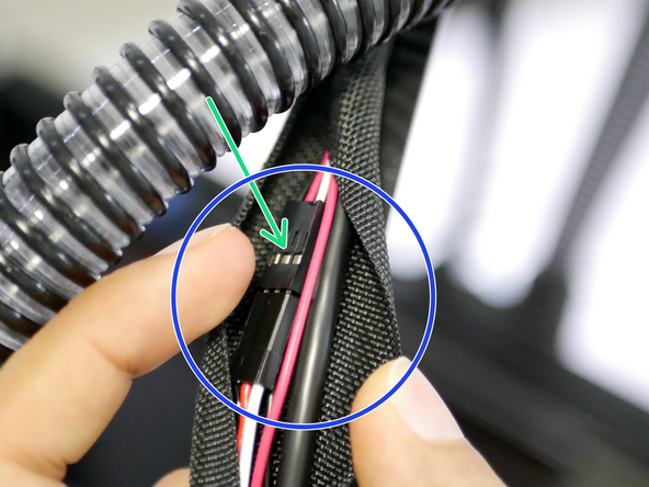
If you have the enclosure upgrade add the extension cable for the fume filter to the loom here also.
-
Fume filter fan extension cable - found in the enclosure upgrade bag.
-
The male side of the cable goes down into the base.
-
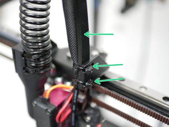
Cable tie the whole loom to the 3d printed bracket.
-
-
-
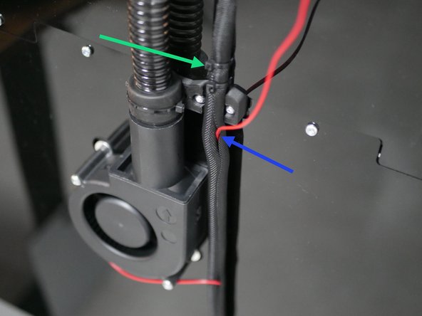
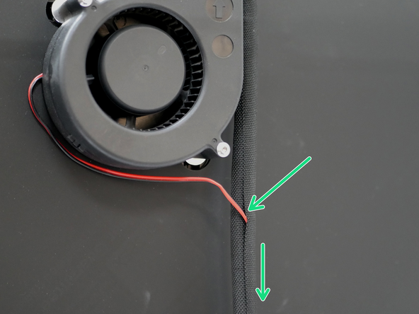
Attach to the part cooling fan its extension cable and feed and feed it into the cable sleeving.
-
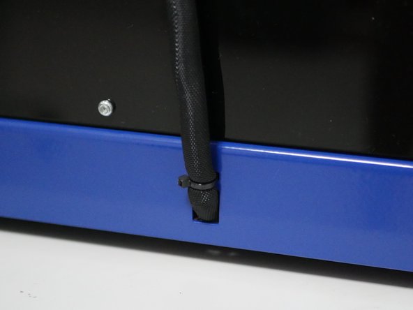
Finally feed the cable loom into the rear of the base and secure with a cable tie.
-


Cancel: I did not complete this guide.
2 other people completed this guide.
