-
-
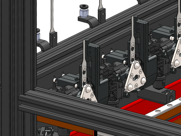
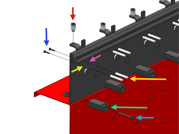
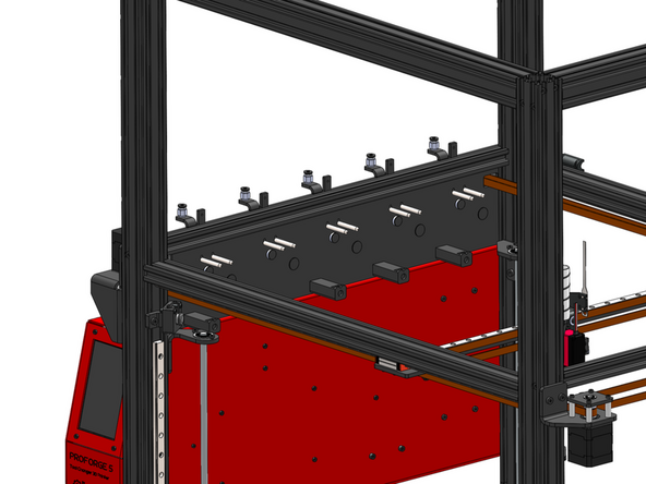
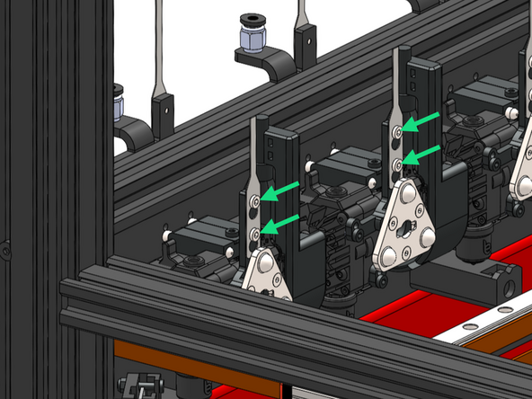
Install the docking pins and ooze shield as shown. If you have less than 5 print heads install from the front to the back.
-
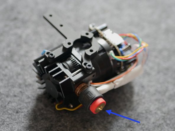
PC4 - M6 Pneumatic Coupling
-
M3 x 12mm Bolt (2x)
-
We recommend to add a drop of 243 thread locker on these bolts.
-
M3x5x30mm Docking Pin (2x)
-
If you have the REVO Print Head upgrade, secure the pins to the upper holes.
-
Silicone Ooze Shield
-
M4 x 40mm FH (Flat Head)
-
-
-
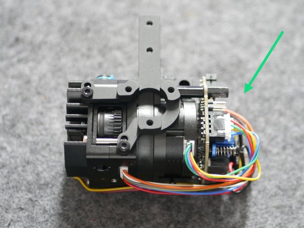
Print Heads ship in the default SO3 config with brass CHT nozzles. If you purchased REVO upgrades, follow these next few steps titled "REVO" to convert them. If not, skip.
-
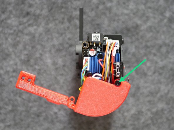
Remove plastic electronics cover.
-
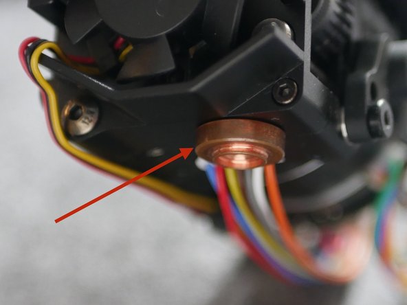
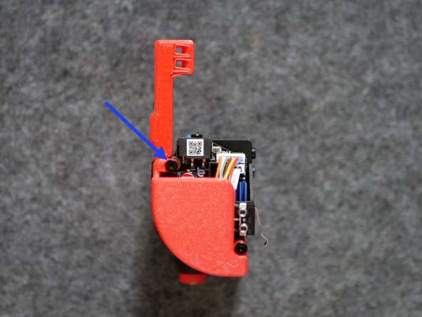
Remove the SO3 Heater.
-
-
-
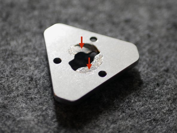
Add lubricant to the inside of the tool plate.
-
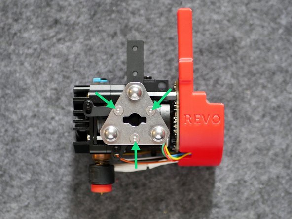
Fix to the print head with three M3 x 8mm counter sunk screws.
-
-
-
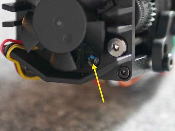
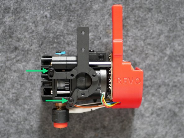
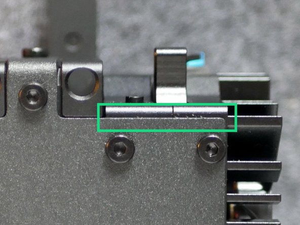
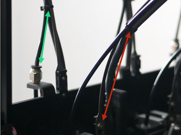
Check that the docking bracket is secure and parallel to the extruder body.
-
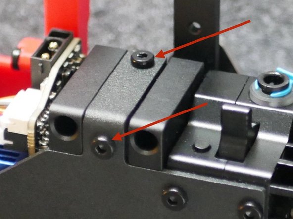
Check that the docking lug is securely mounted to the bracket.
-
-
-
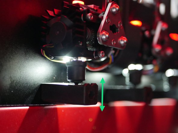
Slide the print heads onto the docking pins and adjust the silicone docks so that they apply slight upward pressure on the nozzle.
-
-
-
Slide the print heads onto the docking pins.
-
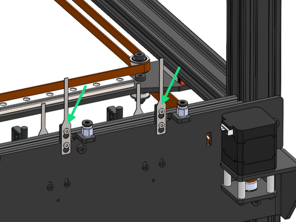
Secure the cable guides to the Frame and Print Heads.
-
M3 x 4 FH (Flat head)
-
-
-
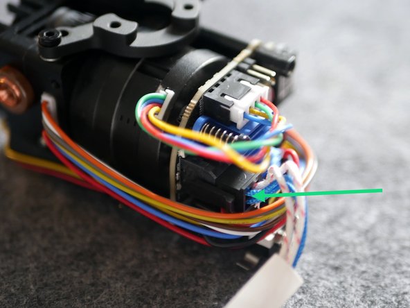
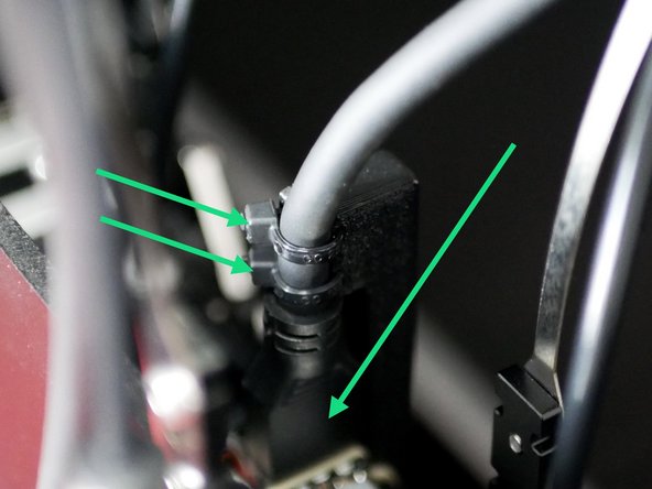
Connect the print head cable to the print head. Use two cable ties to hold in place.
-
If you have the enclosure upgrade do not cable tie here yet.
-
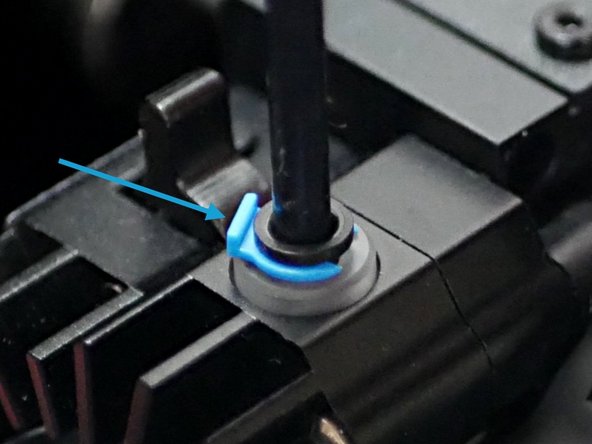
Pull the blue clip and push the PTFE tube into the print head. Push the clip back to secure the tube.
-
Repeat for all print heads.
-
-
-
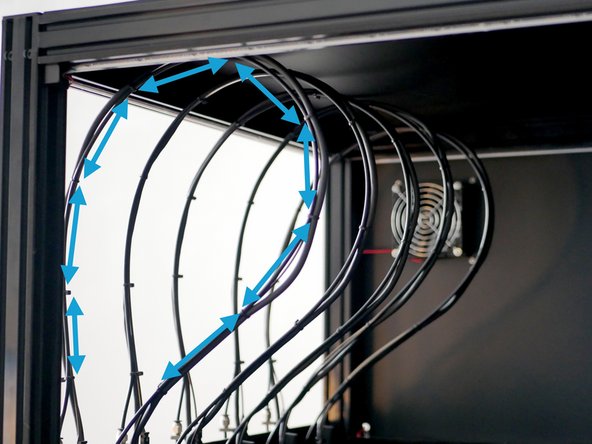
Secure the cable and filament tube to the spring steel cable guide using cable ties.
-
Position the first cable tie 10cm above the print head.
-
Space cable ties around 10cm apart.
-
Fix the final cable tie 5cm above the coupling.
-
-
-
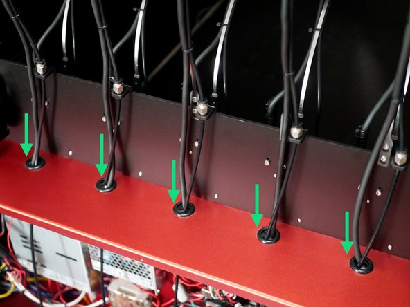
Feed the print head cables and filament tubes into the electronics box.
-
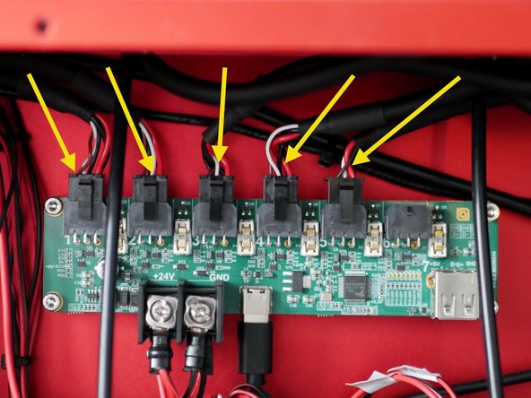
Connect the print heads to the hub board. Order is not significant however we recommend ordering from right to left in order of the first (front) print head to the last (rear) print head.
-
The image shows the filament tubes being pushed through and into the electronics box, however we recommend doing this after that wiring stage.
-
Cancel: I did not complete this guide.
8 other people completed this guide.
