
-
-
Download the Marlin firmware depending on your Hotend configuration (updated 9 April 2022):
-
-
Low / High (Low thermistor on left side T0)
-
Unzip and copy the firmware.bin file to the micro SD card.
-
Insert the SD card into the control board.
-
-
-
Double check all of your wiring with the wiring diagram.
-
In particular, the wiring of the power supply and heated bed.
-
-
-
Plug the power cable into the back of the printer.
-
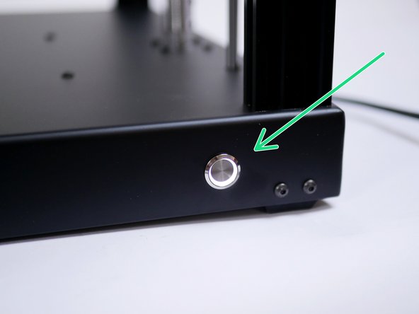
Power on with the switch on the front of the base.
-
If you find your power switch getting stuck 'ON', it is likely secured on too tightly. Loosen the nut holding it to the base.
-
-
-
Powering on for the first time should result in the following:
-
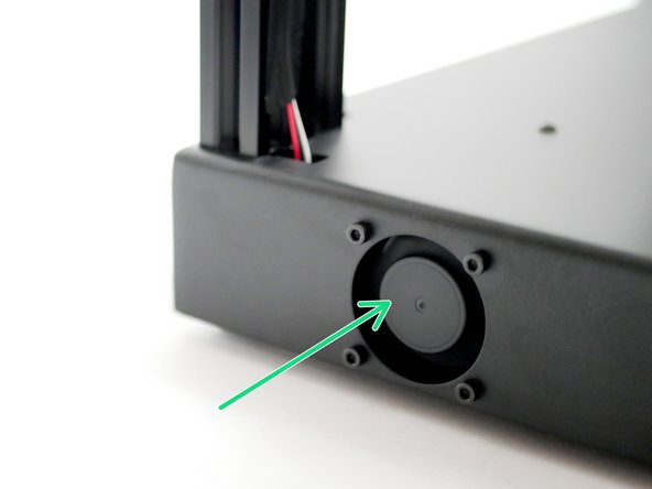
Electronics Fan should spin.
-
Hotend Cooling Fans should spin
-
LED's should light up.
-
If after 1-2 minutes your electronic's fan is not spinning, power off, wait 10 seconds and power on again.
-
-
-
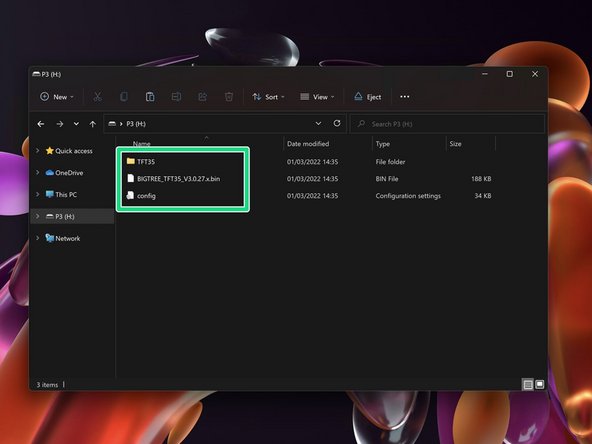
Download the display firmware for the DSH set-up here.
-
Delete any files on the SD card and copy these files onto the SD card.
-
If you have already uploaded direct drive firmware to the touch screen, you can copy just the config file.
-
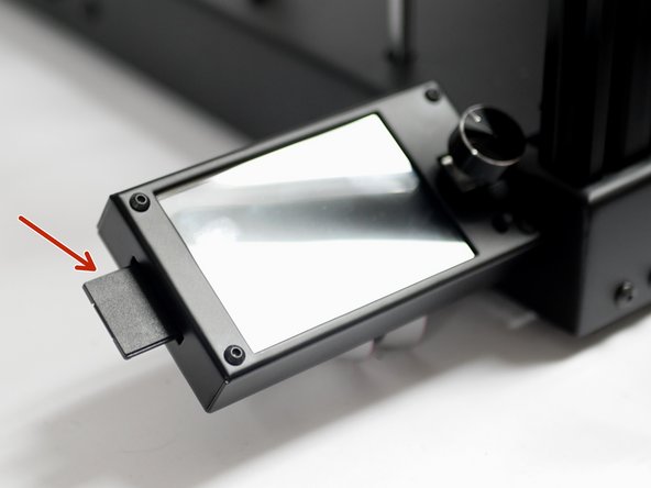
With the printer powered down, insert the SD card into the display with the adaptor.
-
-
-
If your touch screen shows an Illegal flash app error:
-
1. Wipe the SD card and put an empty text file named reset.txt onto it.
-
2. Power off the printer, insert the SD card into the display and power on again.
-
3. After the reset, power down, wipe the SD card, and copy the firmware files again and retry the installation.
-
-
-
Once the touch screen has been updated remove the SD card.
-
Delete the contents of the SD card, it should now be ready to use with your printer.
-
-
-
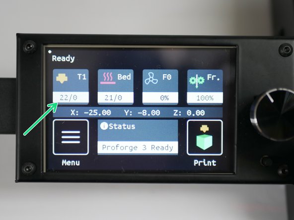
Thermistors should read room temperature.
-
You may find that the hotend thermistor is a little off/jumpy, that's OK as it's a high temp thermistor and designed to be accurate at temps above 100C.
-
-
-
Before starting, make sure that, physically, none of the endstops are being triggered.
-
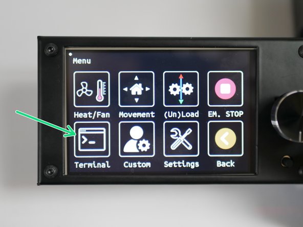
Click on Menu
-
Select terminal.
-
Send an M119 command.
-
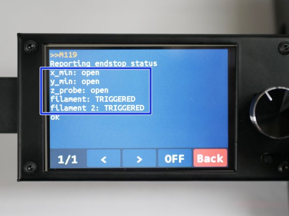
You should receive back that X and Y endstops are open.
-
The Z probe should also be open, and the filament sensors should be triggered (as there's no filament loaded).
-
-
-
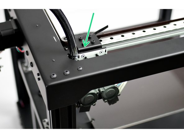
Move the tool head to the bottom left as shown.
-
Both the X and Y endstops should be triggered.
-
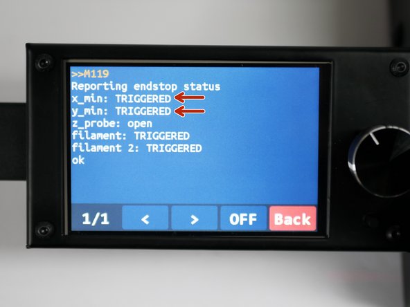
In the terminal, send the M119 command again.
-
You should receive the following back with the X and Y endstops reporting as triggered.
-
-
-
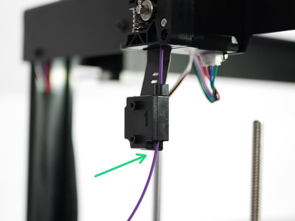
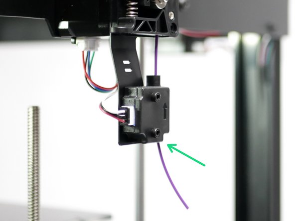
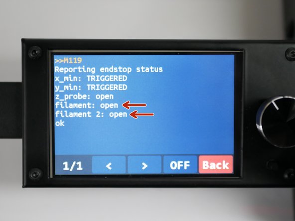
Use a small piece of filament to check that the sensors are working.
-
Sending M119 should return back OPEN.
-
-
-
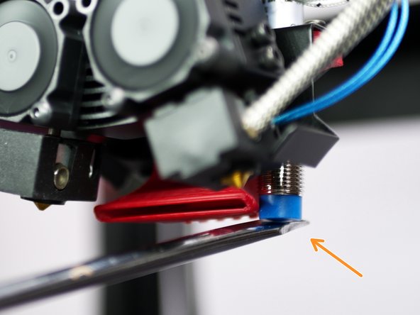
Place a metal object underneath the probe.
-
The LED on the probe should now light up.
-
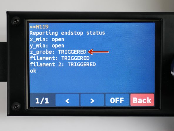
With the metal object still under the probe, send the M119 command again - it should return as TRIGGERED.
-
-
-
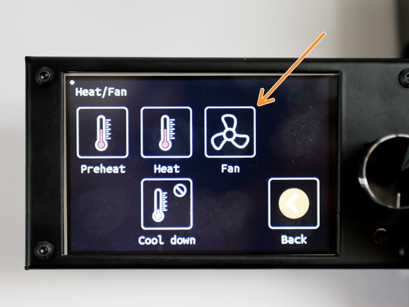
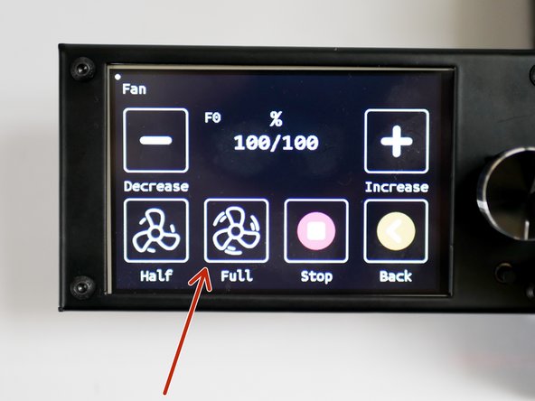
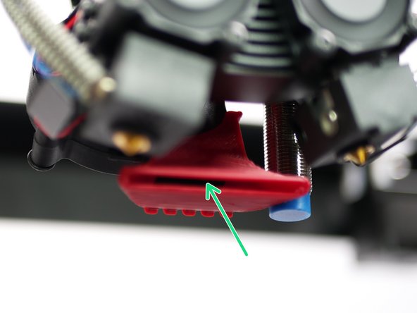
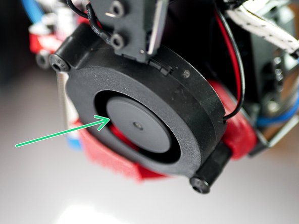
The part cooling fans should be spinning.
-
Switch the fan off when done.
-
-
-
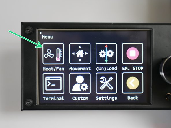
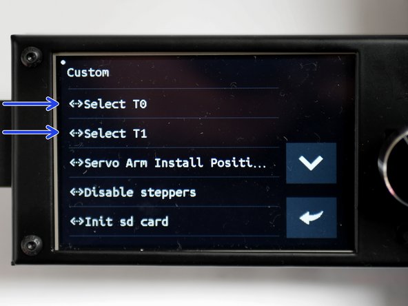
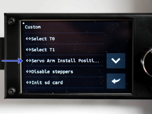
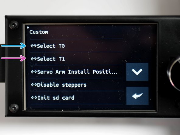
Go to menu and then to custom.
-
Press T0 and T1 to toggle active hotends and check that the servo spins.
-
-
-
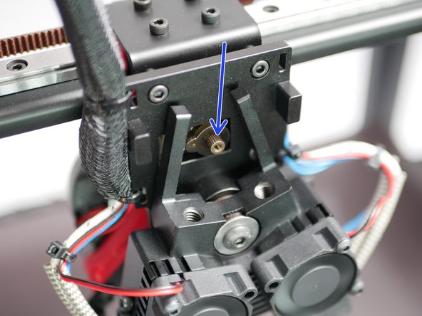
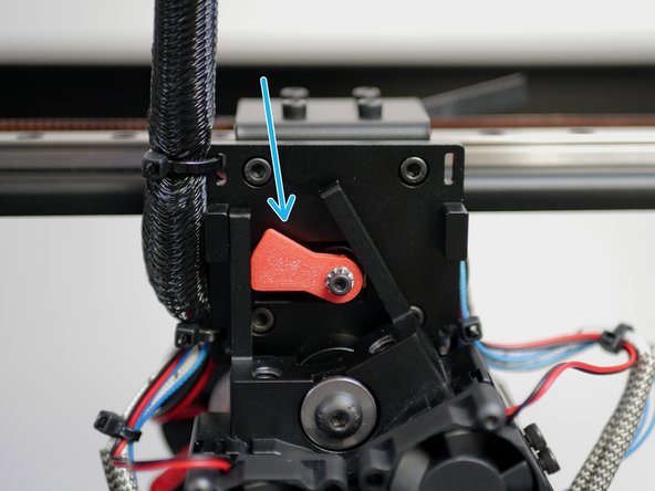
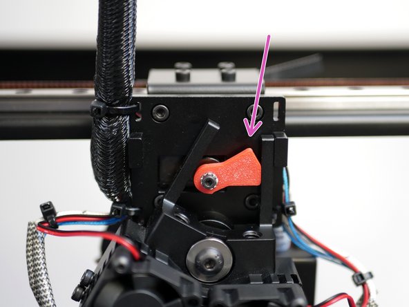
Before installing, make sure that the servo is set to the vertical position. Set this by pressing
-
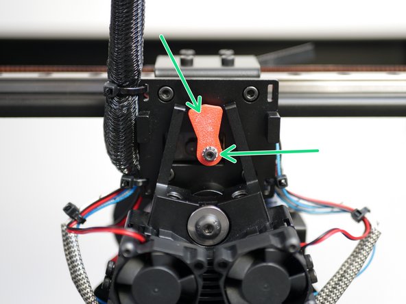
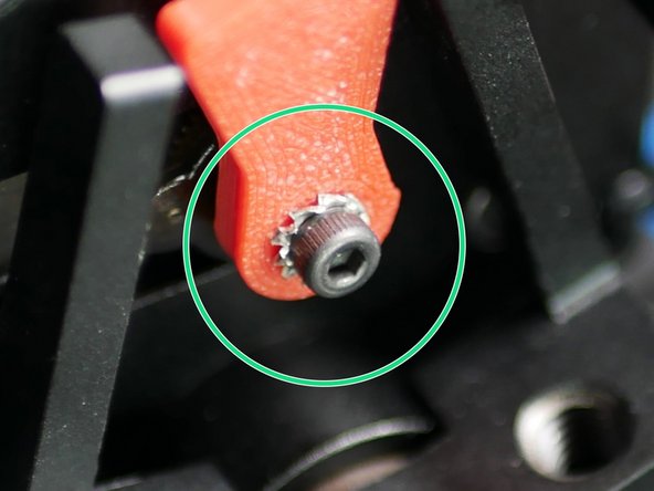
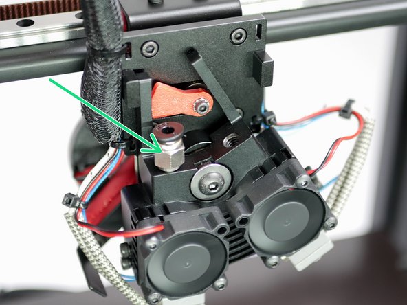
Secure the servo arm with an M2.5 x 6mm bolt and M2.5 shake proof washer.
-
Install the servo arm vertically like shown.
-
Tighten firmly, doing your best to make sure that the servo's position is not changed.
-
-
-
Pressing T0 will select the left hotend.
-
Pressing T1 will select the right hotend.
-
-
-
High temp. setup:
-
Cut 61cm of PTFE tubing
-
Low temp. setup:
-
Cut 65cm of PTFE tubing
-
Ensure you use the tubing from the DSH box, as this is a precision tubing with a 1.9mm internal diameter.
-
-
-
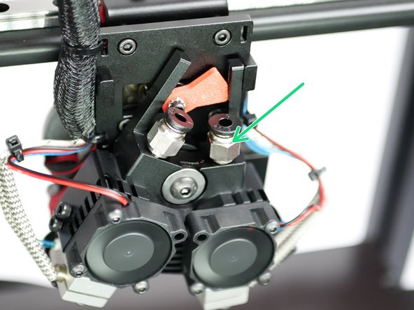
Fix the tubing to the DSH hotend.
-
Make sure that it is pushed in firmly.
-
For the high temp side (all metal heatbreak) it should go in approximately 1 inch.
-
For the low temp side (bored heatbreak) it should go in approximately 2.5 inches, all the way to the nozzle.
-
Not pushing the PTFE tubing all the way into the hotend, as described above, will cause jams.
-
-
-
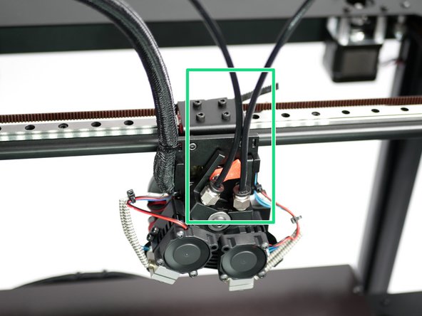
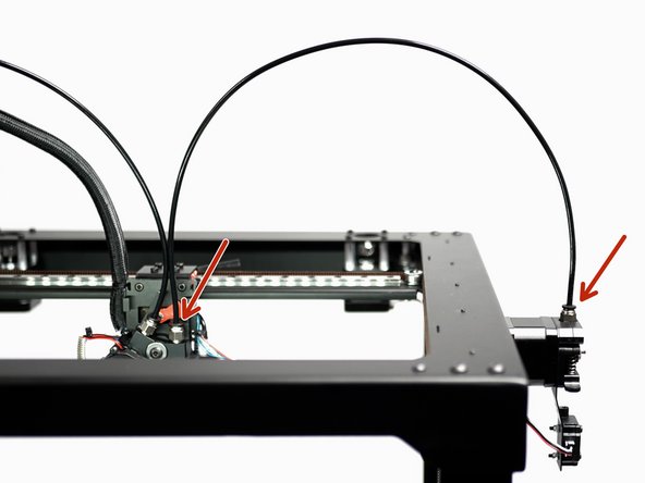
Finally fix the tubing to the extruders.
-
Left hotend to left extruder.
-
Right hotend to right extruder.
-
-
-
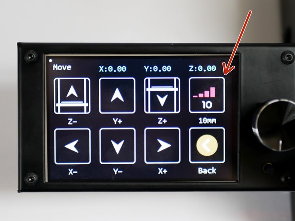
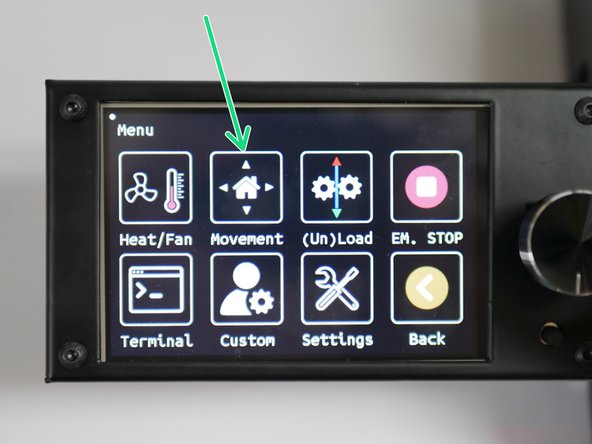
In the menu go to Movement
-
Click on Move
-
Set the motion increments to 10mm.
-
Use the buttons to move the X, Y and Z axes around and confirm that the printer is making the desired movements.
-
-
-
Go to the Movement menu
-
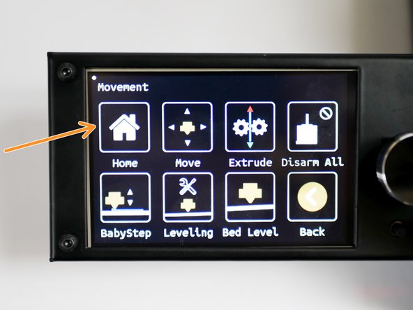
Click on Home
-
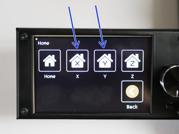
Home X and Y
-
The printer should home those axes.
-
-
-
Before starting, place the flexplate onto the heated bed, if you've not already done so.
-
Before homing the Z-axis, manually raise the platform to meet the tool carriage at the centre of the print platform.
-
Before being able to move the carriage by hand, you will need to disable the stepper motors. This button can be found in the movement menu (Disarm All).
-
The platform should trigger the probe (red light comes on) before the tip of the nozzle touches the flexplate.
-
The probe should always remain above the tip of the nozzle.
-
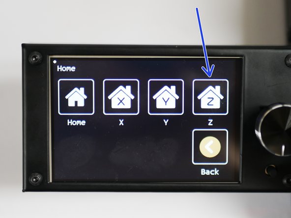
With the above confirmed, home the Z-axis from the dispay.
-
-
-
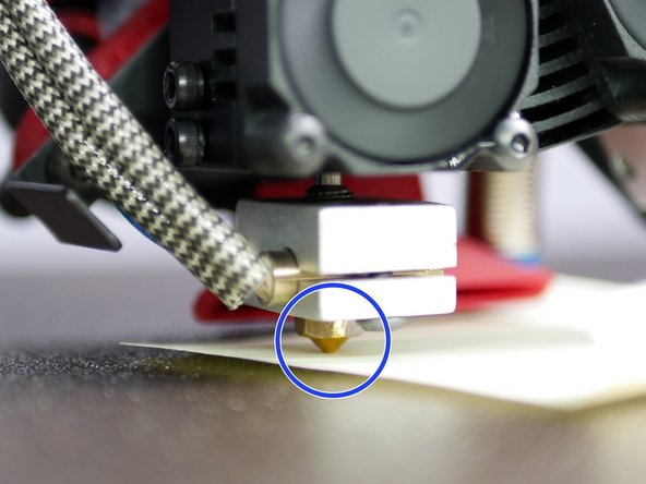
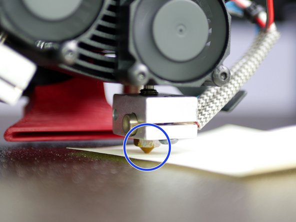
Use a piece of paper to to determine the same amount of friction between the two nozzles and the print surface when switching between hotends.
-
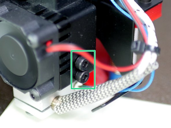
Lower the nozzle that sits higher by loosening the bolts holding it in place.
-
You will likely need to raise the platform manually so that the piece of paper can be gripped between the nozzle and the bed.
-
-
-
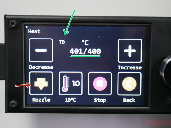
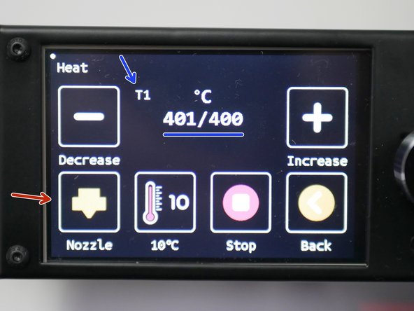
From the home screen click on the hotend.
-
Heat Hotend 0 to 400C.
-
Heat Hotend 1 to 400C.
-
Use the nozzle button to toggle between hotends.
-
For a low temp hotend setup heat to 250C.
-
-
-
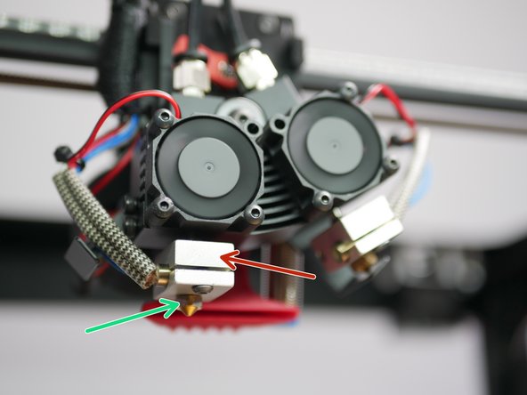
With the hotends hot, tighten the nozzles.
-
Do this using two pliers. Use one to hold the heater block,
-
use the other to tighten the nozzle.
-
Be careful doing this, the hotend is hot enough to cause burns!
-
-
-
There is no need to now run the hotends at max temp, bring them down 200C.
-
With the hotends hot you can send an extrude command to check the extruders are working correctly.
-
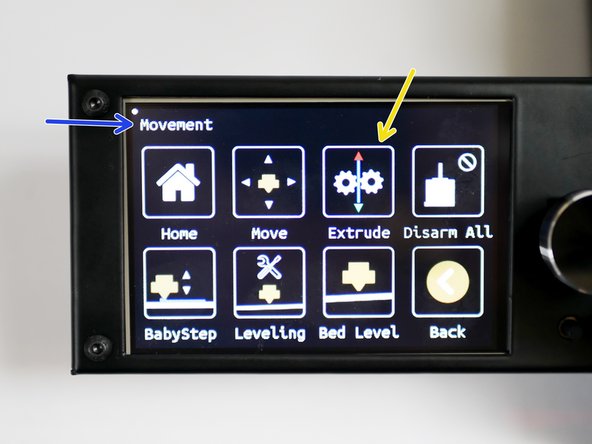
In the main menu go to Movement
-
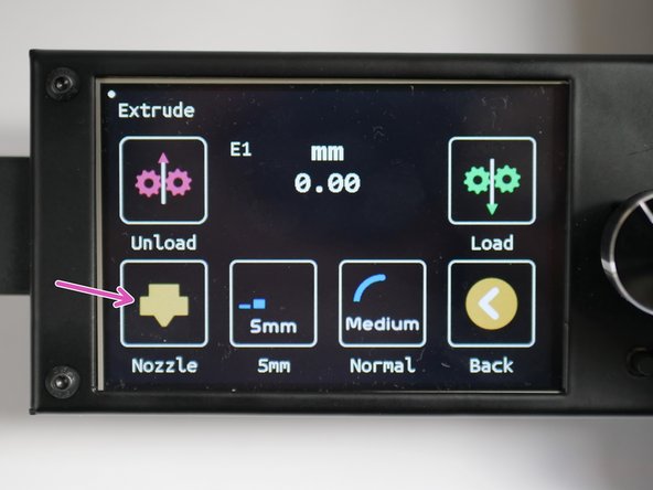
Then go to Extrude
-
Use Nozzle to toggle between extruders.
-
E0 should be the left side extruder. E1 should be the right side extruder.
-
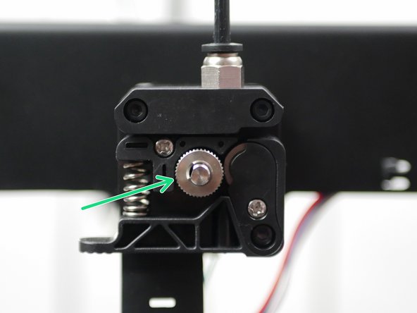
Both extruders should turn anti-clockwise when loading filament and clockwise when unloading.
-
-
-
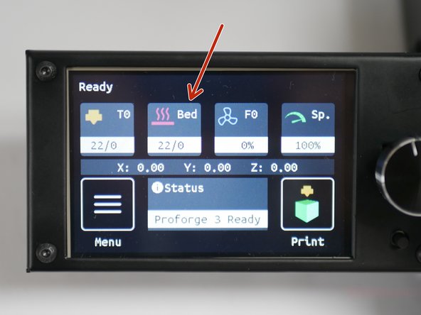
From the home screen, click on Bed
-
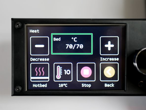
Heat the bed to 70C.
-
MIC-6 NOTE: The printer reads the temperature of the silicone heater, not the platform. Therefore, even though the printer may report back that it has reached its temp, it will take approx 5-10 min for the platform surface to actually reach that temp.
-
-
-
Before beginning this step, make sure that the heated bed and hotend are heated up to your desired printing temp. We recommend 220C on the hotend and 70C on the heated bed as a good starting point.
-
The hotend and platform, when hot, would have expanded. Therefore, the z-offset is different for when the printer is hot versus cold.
-
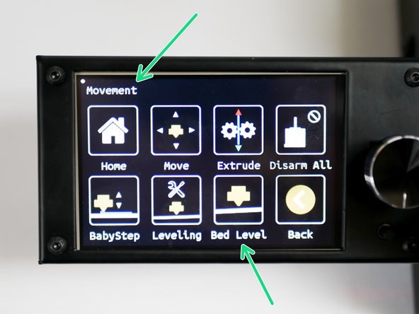
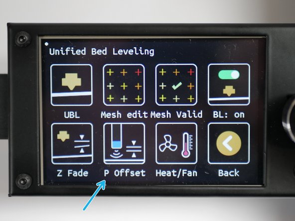
Go to the Movement menu and then to the Bed Level menu.
-
Click on P Offset
-
Press ON to begin the offset calibration.
-
-
-
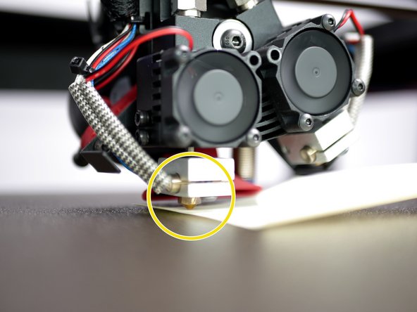
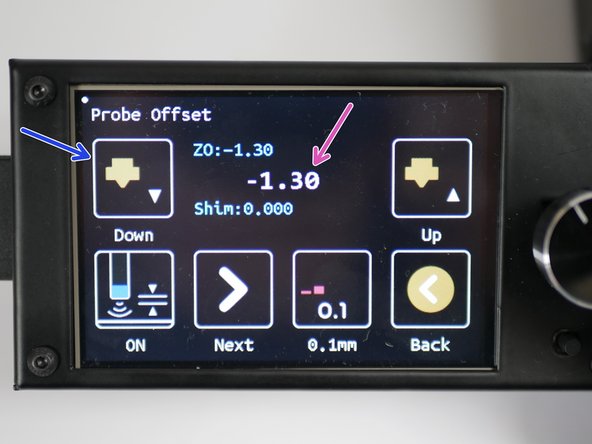
Toggle the adjustment increment to 0.1mm.
-
Place a sheet of paper under the nozzle.
-
Make sure you are doing this with Hotend 0 selected.
-
Lower the nozzle (raise the bed) in 0.1mm increments until the sheet of paper is trapped between the nozzle and platform.
-
In our case, we had to lower the nozzle by 1.3mm before this happened.
-
-
-
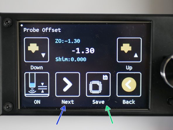
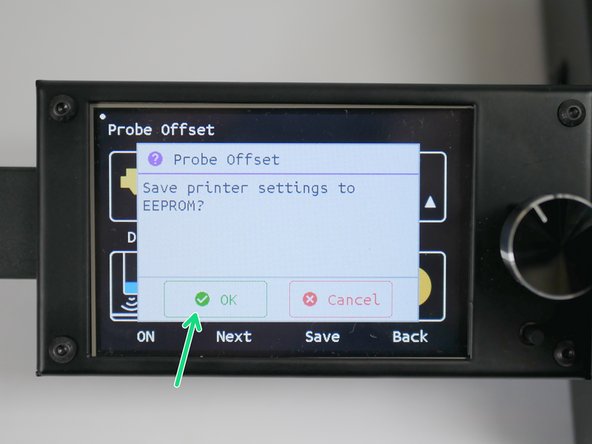
Press next until the save button appears.
-
Press the save button and then press OK to save the offset to the printers' memory.
-
-
-
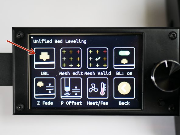
In the Movement -> Bed Level menu, click on UBL
-
Click Start
-
The Proforge 3 should then run through the auto-levelling procedure.
-
Click OK when done.
-
-
-
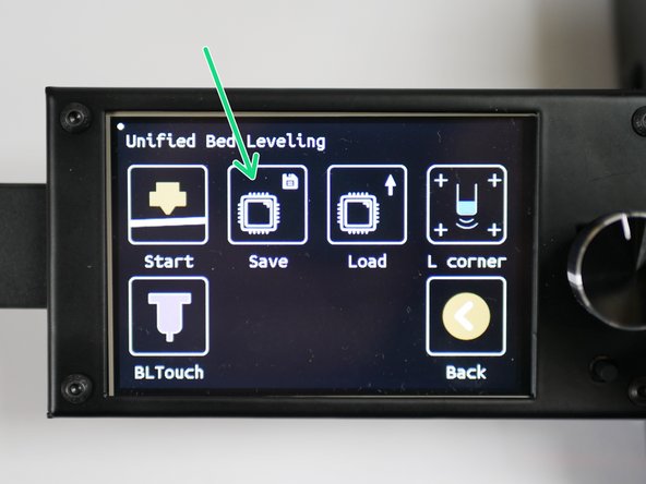
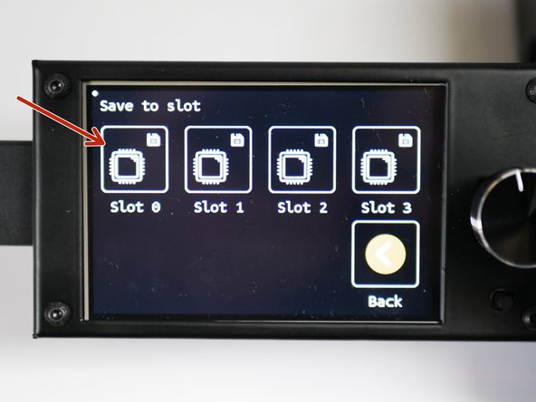
Click Save to save the mesh.
-
Save to slot 0
-
Press OK to confirm the save.
-
-
-
With all of these steps now completed, you are ready to begin your first print.
-


Cancel: I did not complete this guide.
2 other people completed this guide.
