-
-
As of 2024, both sides are high temp sides with the same type of thermistor. If you received your kit in 2024 then use these thermistor values.
-
-
-
Set the thermistors up as shown. Extruder HT is for a high temp side. Extruder LT is for a low temp side.
-
Low temp thermistor (white cable, silver casing):
-
[thermistor Extruder LT] temperature1: 25 resistance1: 100000 temperature2: 72.5 resistance2: 12868 temperature3: 95 resistance3: 6854
-
High temp thermistor (white cable, brass casing):
-
[thermistor Extruder HT] temperature1: 20 resistance1: 4721000 temperature2: 200 resistance2: 8000 temperature3: 400 resistance3: 264
-
High temp thermistor (blue cable):
-
[thermistor Extruder LT] temperature1: 25 resistance1: 4500000 temperature2: 260 resistance2: 2240 temperature3: 460 resistance3: 125.4
-
-
-
Setup your config so you have two extruders.
-
Shown is just an example config, do not copy this exactly. You will need to edit these values based on your printer.
-
Set the thermistors based on whether you have installed a high/low temp setup or a high/high temp setup.
-
For the 2024 thermistors set this to just Extruder.
-
-
-
Create a section named [servo extruder]
-
[servo extruder] pin: PE5 maximum_servo_angle: 180 minimum_pulse_width: 0.0004 maximum_pulse_width: 0.0024
-
Set the pin value to where you have plugged the servo signal line into your control board.
-
Create a section named [output_pin servo_power]
-
[output_pin servo_power] #Set low to power off servo pin: PE6 pwm: False
-
Similarly, set the pin value to where you have plugged your relays signal line into.
-
-
-
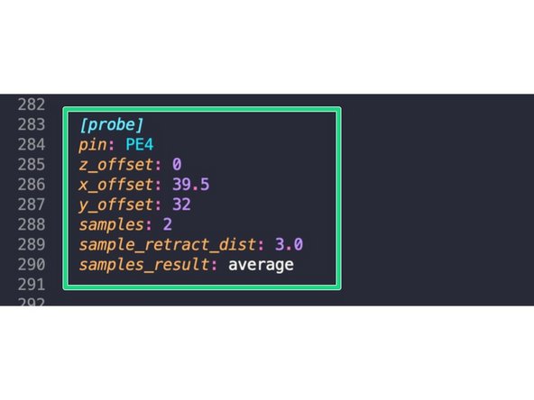
Set the probe up as shown, again setting the pin value based on where you've plugged the probe to your control board.
-
[probe] pin: PE4 z_offset: 0 x_offset: 39.5 y_offset: 32 samples: 2 sample_retract_dist: 3.0 samples_result: average
-
-
-
Copy the following macros into your macros.cfg file.
-
-
-
-
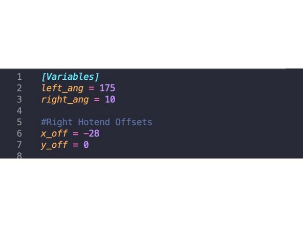
If you don't already have a variables.cfg file, create one and add the following code to it.
-
-
-
-
Finally, add to the top of your printer.cfg the following:
-
[save_variables] filename: ~/klipper_config/variables.cfg
-


![Create a section named [servo extruder]](https://d3t0tbmlie281e.cloudfront.net/igi/makertech-3d/1Z1FonhloJmY5Tcw.medium)