-
-
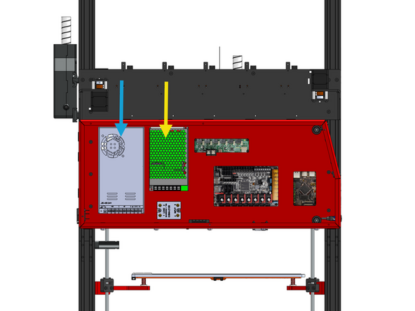
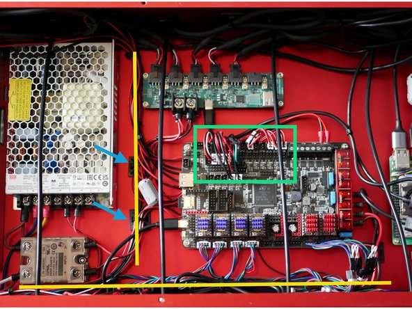
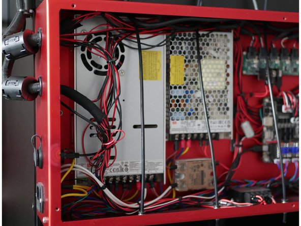
Inside the electronics box you will find two power suppliers.
-
24V PSU
-
48V PSU
-
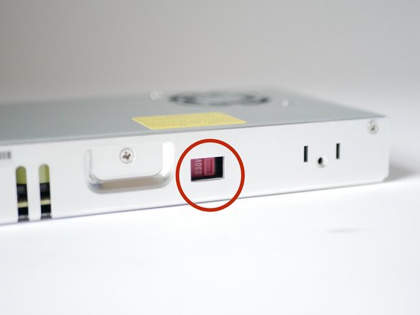
Before continuing check that the voltage switch on the side of both power supplies is set correctly.
-
Ensure the voltage selector switch on the side of the unit is set to match your local mains supply before powering on. For example, this should be set to 230V in most of Europe and 110V in North America.
-
By default all are set to 230v.
-
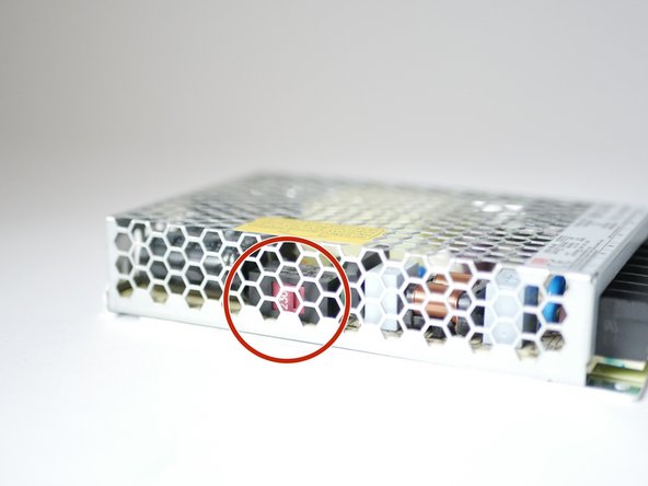
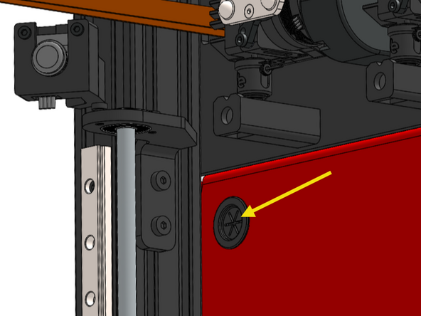
We recommend temporarily removing the smaller 48V power supply to access the voltage selector switch on its side. When reinstalling the 48V supply, align the mounting hole on the power supply with the hole in the electronics enclosure by looking through the access opening. Once aligned, secure it in place using the M3 bolt.
-
-
-
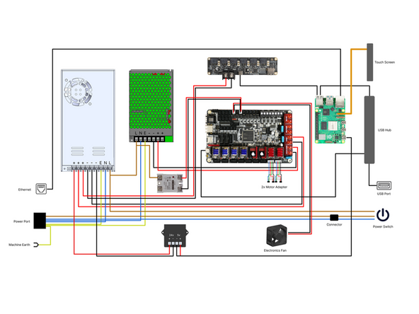
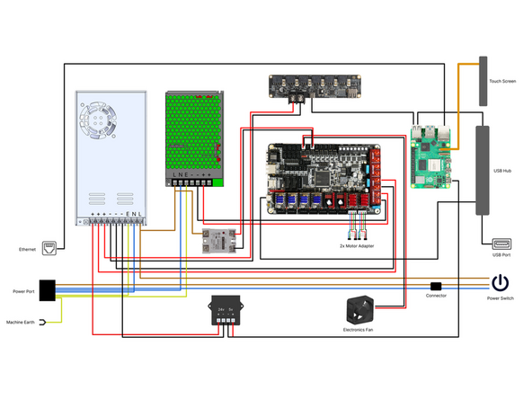
Check that all wiring inside the electronics box matches the wiring diagram here. Pay particular attention to the terminal connections, ensure all screw terminals are fully tightened and that none have loosened during shipping.
-
-
-
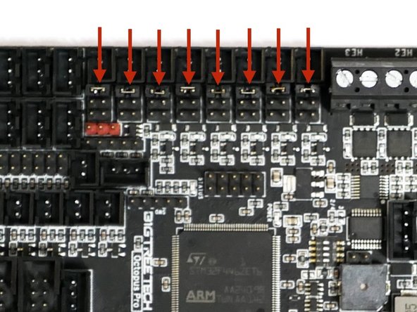
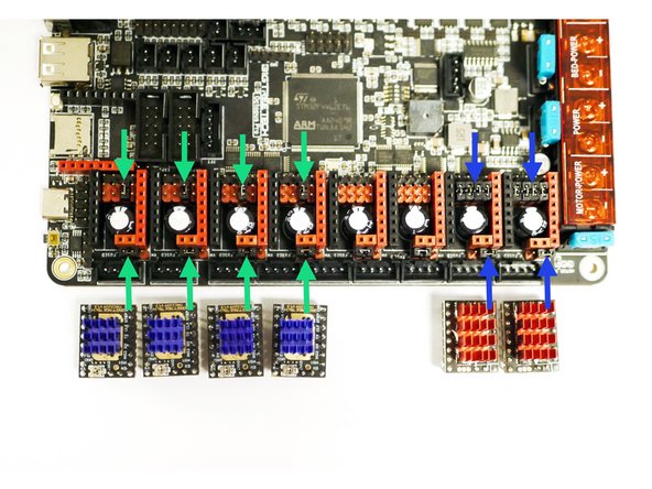
The control board should have jumpers pre-installed in these locations.
-
All jumpers set to 24v
-
Single jumper under Z-motor drivers
-
Z-motor power set to 24v
-
Row of 4 jumpers under X/Y motor drivers
-
X/Y motor power set to 48v
-
-
-
Route the bed cables in from the underneath of the electronics box.
-
-
-
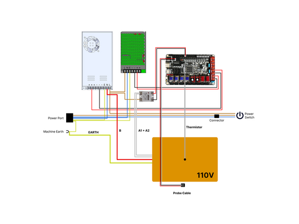
If your mains voltage is 110V wire the bed according to this diagram.
-
Known issues:
-
The pre-installed black and red SSR signal cable may be reversed, ensure that the path matches as shown in the diagram regardless of cable colour.
-
The probe cable wire colours may be in reverse order, this is ok provided the wiring remains consistent from the connector through to the control board as shown in the diagram.
-
Updated 110V Mains Harness - All units shipped after 20th March 2026 will have the updated harness with Waygo connectors for connecting bed cables.
-
-
-
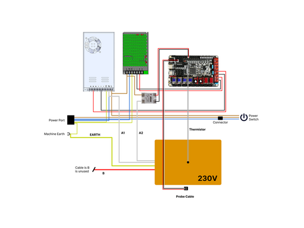
If your mains voltage is 230V wire the bed according to this diagram.
-
The pre-installed black and red SSR signal cable may be reversed, ensure that the path matches as shown in the diagram regardless of cable colour.
-
The probe cable wire colours may be in reverse order, this is ok provided the wiring remains consistent from the connector through to the control board.
-
-
-
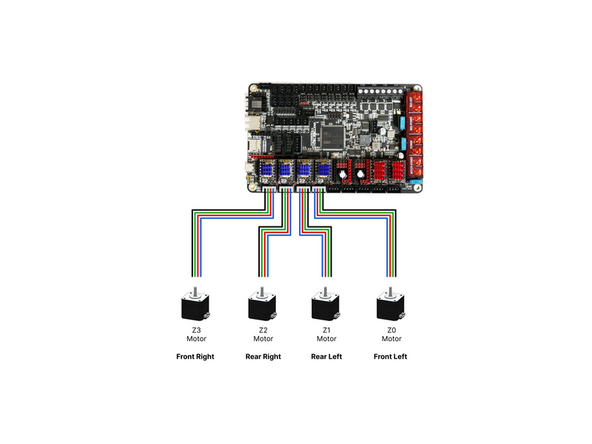
The Z-motors have two sets of cables. Two short and two long. They are packed alongside the Z-motors.
-
Wire the motors to the control board as shown, with the two shorter cables used on the motors nearest the electronics box.
-
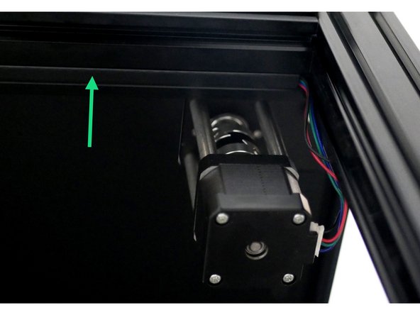
Route the cables through the grooves of the extrusion. Cut appropriate lengths of the included cable cover and press them in place to tidy the cables.
-
If you have the enclosure upgrade, feed the motor cables up through the holes in the left side of the base panel.
-
-
-
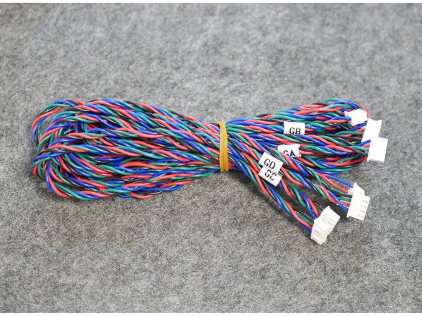
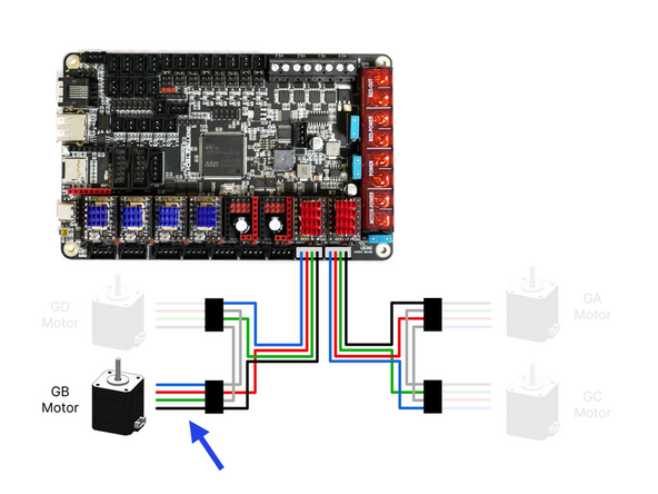
Gantry motors cables are packed next to the gantry motors.
-
The cables are of different length and labeled GA, GB, GC and GD at the control board side connector.
-
-
-
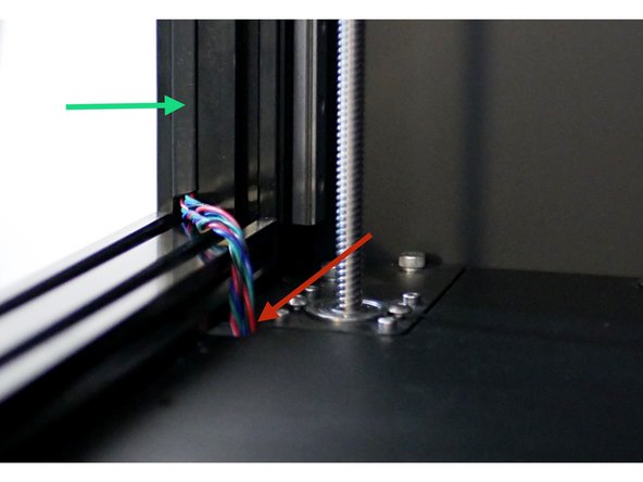
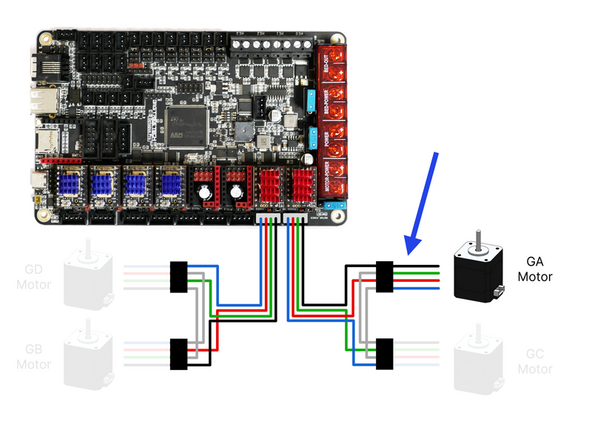
Start with the Gantry A motor at the front left.
-
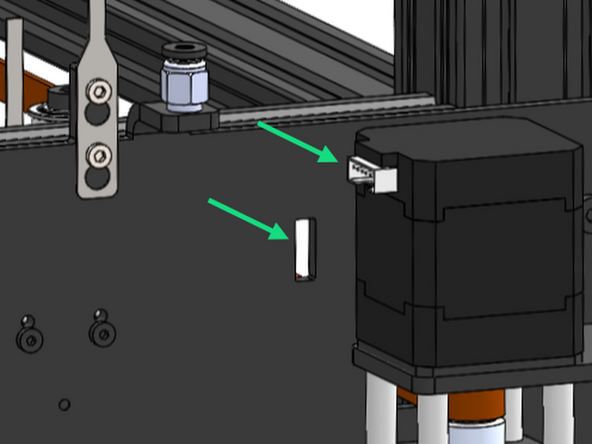
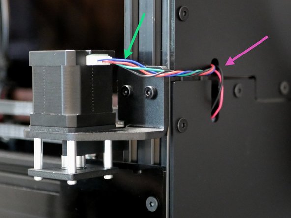
Connect the motor side cable first by feeding it through the inside of the cutout on the bracket panel.
-
Feed the rest of the cable into the electronics box though the upper inside hole.
-
Connect the cable to the motor adapter.
-
-
-
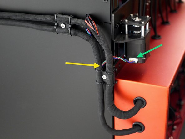
Connect the GB cable the gantry B motor in the rear left.
-
Feed the cable through the cooling fan loom and into the electronics box from the rear.
-
Connect the cable to the second adapter.
-
-
-
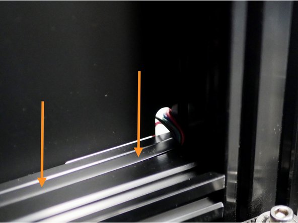
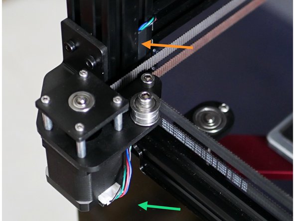
Connect the GC cable to the gantry C motor (right rear).
-
Route the GC motor cable and X-Endstop cable around the rear of the frame and through the panel if you have the enclosure upgrade.
-
Cut a length of the cable cover to hold both cables in place on the rear groove of the extrusion.
-
-
-
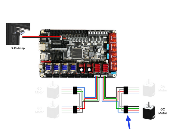
Feed the Gantry C and X-Endstop cables through the part cooling fan sleeving and into the electronics box.
-
If you have the enclosure upgrade feed the cables though the hole on the rear panel.
-
Plug the motor cable into the adapter with the GA motor. and plug the X-Endstop into the position on the board as shown.
-
-
-
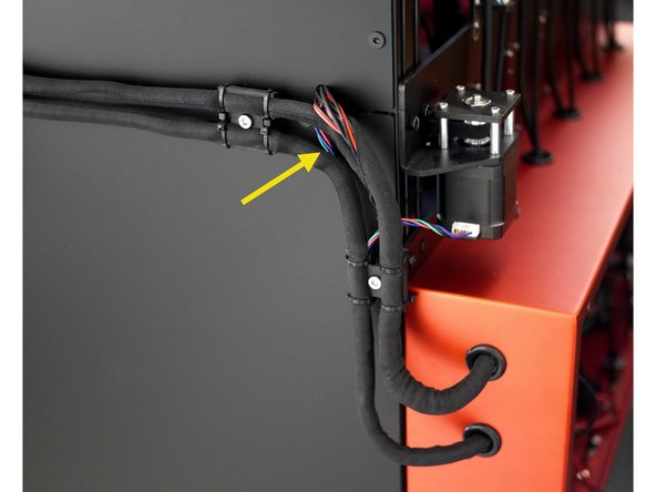
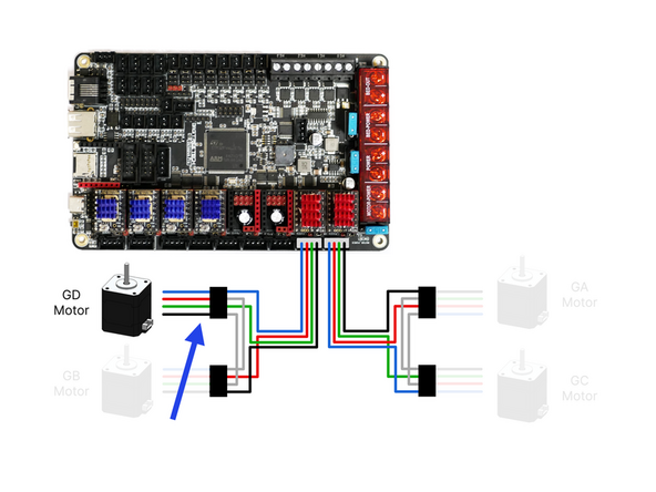
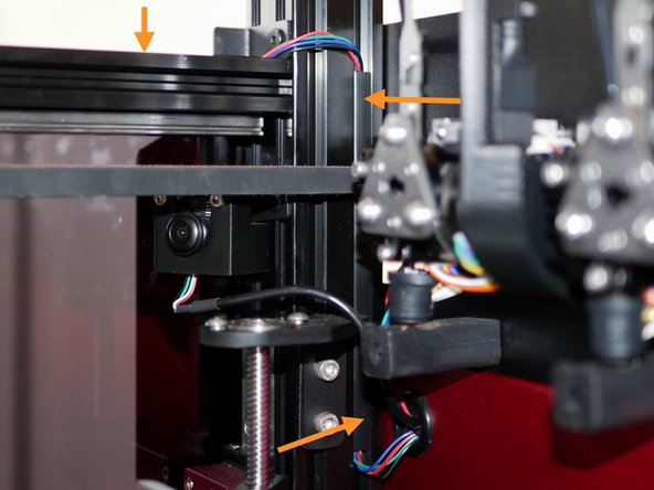
Plug the GD motor cable into the front right motor.
-
Route the cable through the inside of the frame as shown.
-
Cut a small strip of the cable cover to route the cable behind the belts.
-
Cut a long strip to hold the cable down over the rail extrusion.
-
Use another small strip to route the cable behind the belt and into the electronics box.
-
Connect the DG cable to the adapter cable.
-
-
-
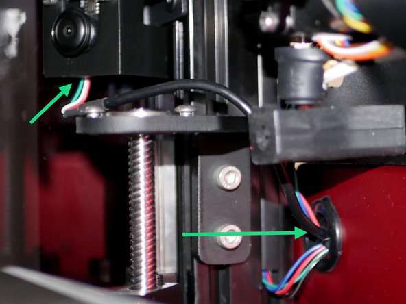
Route the camera cable through the upper inside hole of the electronics box.
-
Plug the camera into the USB hub.
-
Tip: It is easier to feed the cable in though the electronics box and to the camera.
-
-
-
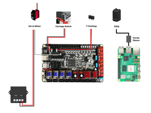
Wire components from the tool carriage as shown in the diagram.
-
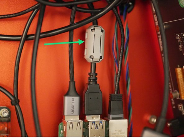
There are four (black) ferrite sleeves included: two large, one medium, and one small. Take the medium-sized ferrite sleeve and clamp it around the Eddy probe’s USB cable.
-
-
-
Use rubbing alcohol or a damp clean cloth to clean the upper inside surfaces of the frame to remove any dirt or grease.
-
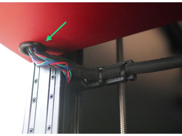
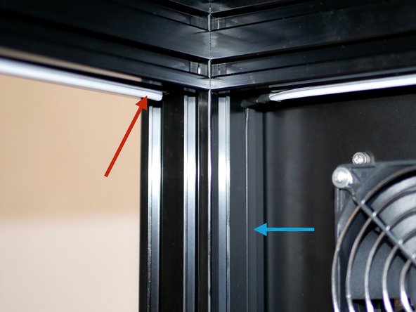
Take the RGB LED roll and peel away the backing paper from the last section, the one furthest from the cables.
-
Stick this section to the upper left side, starting from the rear corner.
-
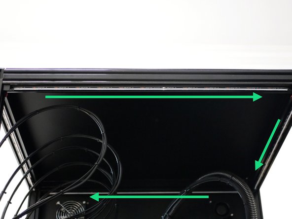
Stick the rest of the LED strip around the upper front, right and rear of the frame in this order.
-
Cut 30cm of the cable cover to hold cable in place, feed it into the rear of the electronics box via the tool carriage cable sleeving.
-
-
-
Wire the RGB case light as shown.
-
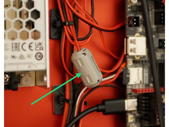
Add the smallest included ferrite sleeve to the RGB's signal cable.
-
-
-
If you do not have the enclosure upgrade the next steps titled "Enclosure: ..." can be skipped.
-
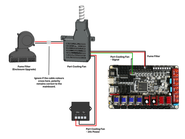
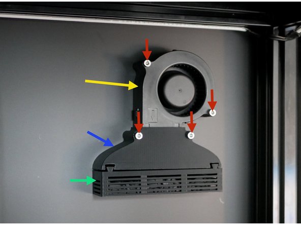
Install the fume filter.
-
Fume Filter Fan Shroud
-
Fume Filter Tray
-
Filter Blower Fan
-
M4 x 40mm + Nyloc Nut
-
When installing feed the fans cable though the hole on the enclosure panel and connect the cable to the extension cable coming from the part cooling fan box.
-
-
-
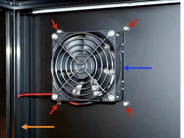
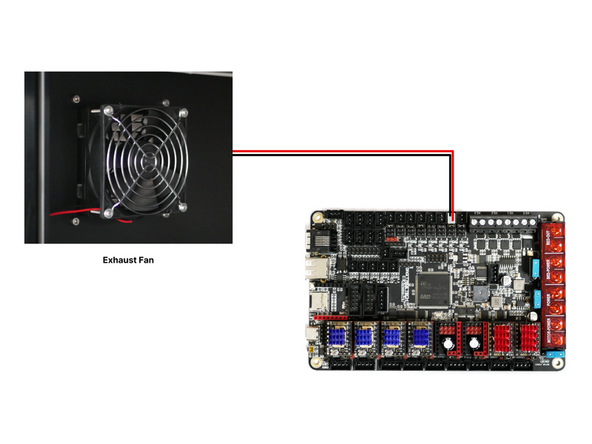
Mount the exhaust fan.
-
Exhaust Fan
-
4x M4x8mm Bolt
-
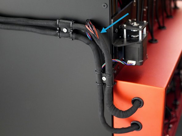
Feed the cable down the grove, use a 20cm strip of cable cover to hold the cable.
-
Feed the cable thought the rear of the electronics box the tool carriage loom.
-
Connect the exhaust fan to the control board as shown.
-
-
-
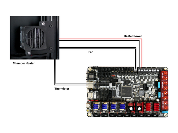
Mount the heater to the rear right of the frame.
-
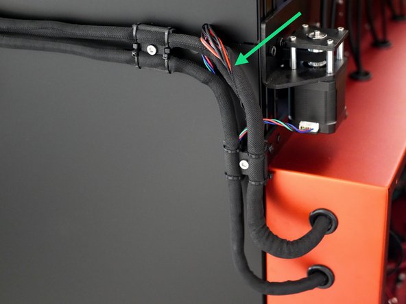
Route the cable through the groove in the extrusion using a length of cable cover to hold in place.
-
Feed the cables in the rear of the electronics box though the tool carriage loom.
-
Wire the heater as shown in the diagram.
-
Note, the fan and thermistor cables are both black, however the fans cables are thicker.
-
-
-
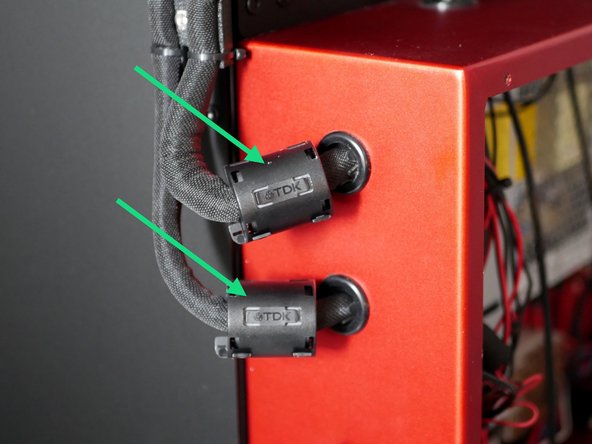
Clip the two large ferrite sleeves to the cable looms entering the rear of the enclosure.
-
-
-
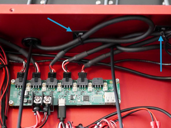
Use cable ties to loop together excess cable.
-
Too keep things tidy we recommend routing these cables under the control board as shown.
-
We also suggest routing cables through these channels.
-
Use the included cable tie mounts to hold cables in place.
-


Cancel: I did not complete this guide.
6 other people completed this guide.
