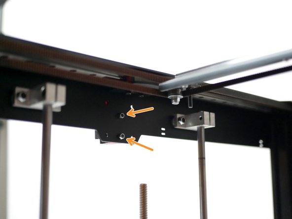
-
-
If you plan to run the Proforge 3 with the Direct Drive extruder please continue to follow this guide.
-
If you intend to install the Dual Switching Hotend please continue your build from here.
-
-
-
Locate these four parts for the Hotend:
-
Heatsink
-
Heater Block
-
Heatbreak
-
Nozzle
-
Secure the Heatbreak into the Heatsink.
-
-
-
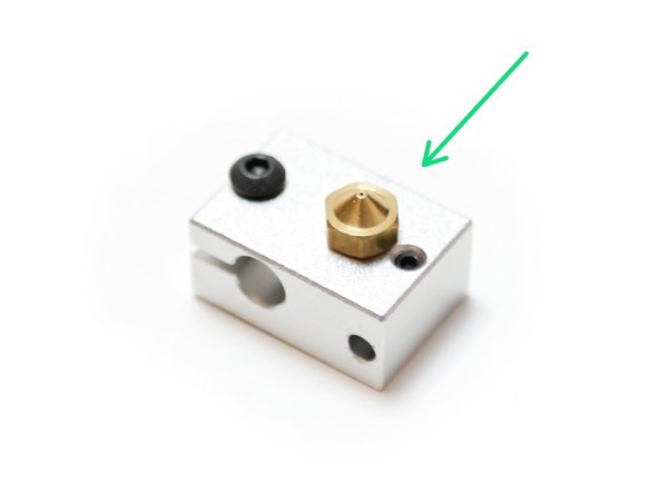
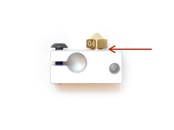
Fasten the Nozzle into the heater block.
-
Note the side that it's fastened into.
-
Also leave approximately a 1mm gap between the nozzle and heater block.
-
-
-
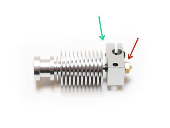
Fasten the Heater Block assembly to the Heatsink assembly.
-
Apply the turning force through the nozzle.
-
Be careful not to apply too much force when tightening, as it may cause the heatbreak to snap!
-
-
-
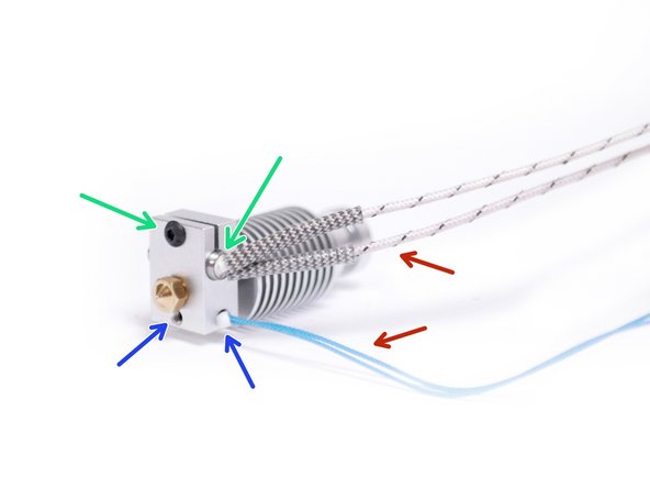
Fix the heater cartridge as shown. Tighten this bolt to secure it.
-
Slide the thermistor cartridge in place. Tighten this set screw to secure.
-
Make sure that the cables are point out of the side shown.
-
-
-
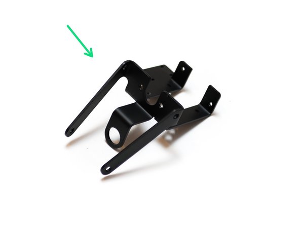
Locate the Direct Drive Mount bracket.
-
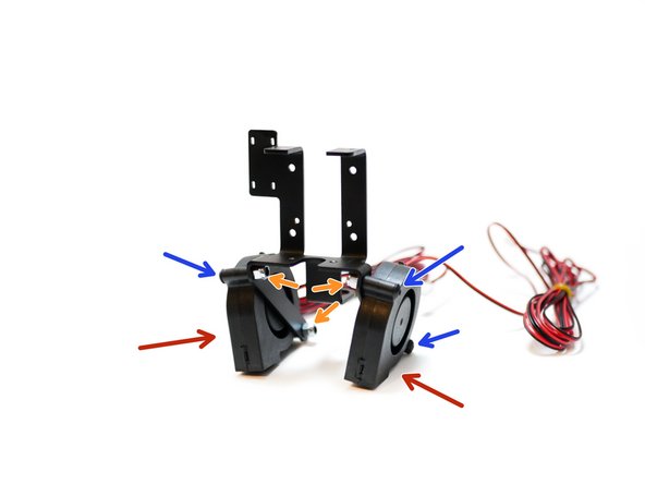
Secure to it the two 50mm blower fans as shown.
-
M4 x 22mm Button (x4)
-
M4 Nyloc Nut (x4)
-
-
-
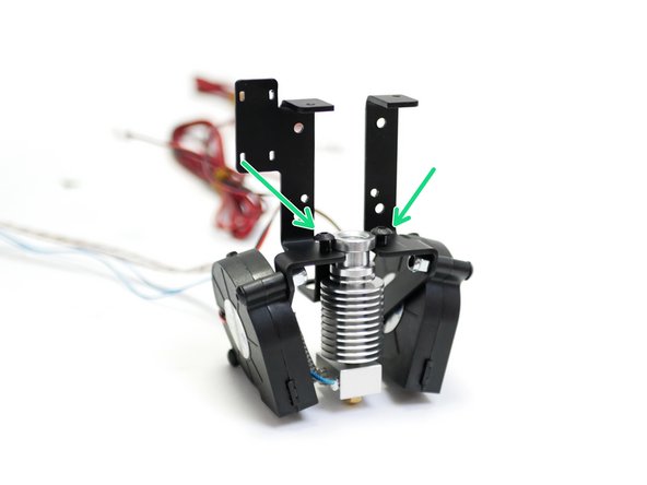
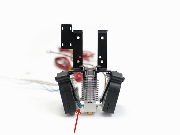
Fix the Hotend to the Mount with two M4 x 8mm button bolts.
-
Ensure the Hotend is pushed all the way into the mount.
-
Ensure that the Hotend's cables point to the left.
-
-
-
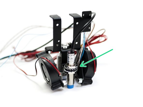
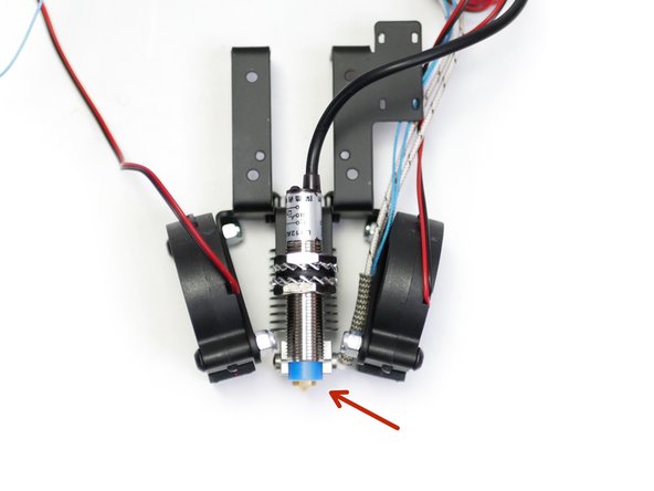
The probe is secured to the back of the Mount as shown.
-
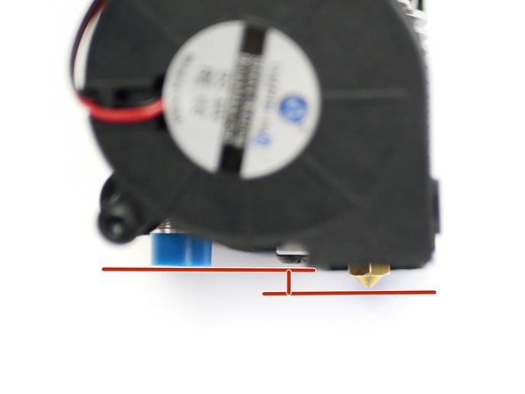
The bottom of the probe should be between 1-2mm above the tip of the nozzle.
-
-
-
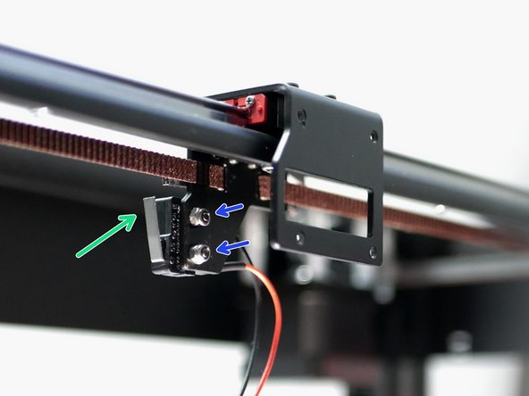
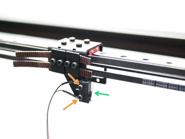
Install the X-Endstop as shown.
-
Note that the X-Endstop is the one with the longer 2M cable.
-
M2.5 x 12mm Bolt
-
M2.5 Nyloc Nut
-
-
-
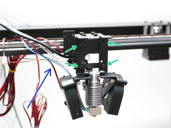
Secure the Mount to the Tool Carriage on the gantry.
-
M3 x 6mm Cap Bolt
-
Have the cables come out of the left side of the mount.
-
-
-
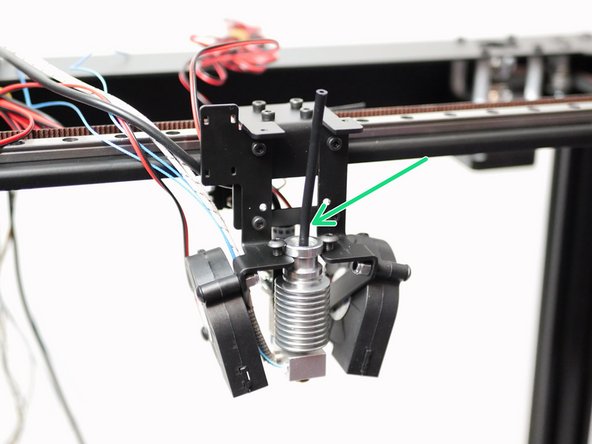
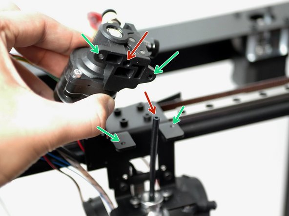
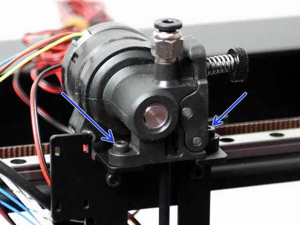
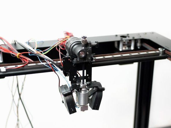
Secure the Orbiter Extruder as shown.
-
The mounting holes line up with those on the hotend mount.
-
The PTFE tube goes into this hole.
-
Secure with two M3 x 8mm Cap head bolts.
-
-
-
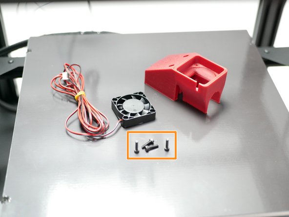
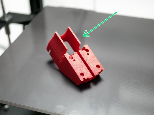
Take the 3D printed mount and remove the support raft from underneath.
-
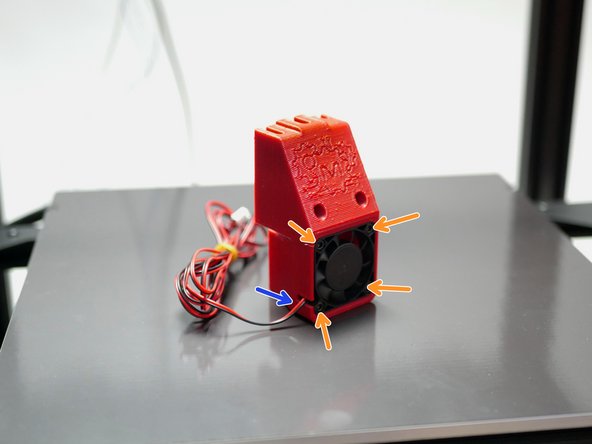
Fix the fan with 4 M3 x 12mm bolts.
-
Ensure the fan is installed sticker side in and with its cable aligned with the slot.
-
-
-
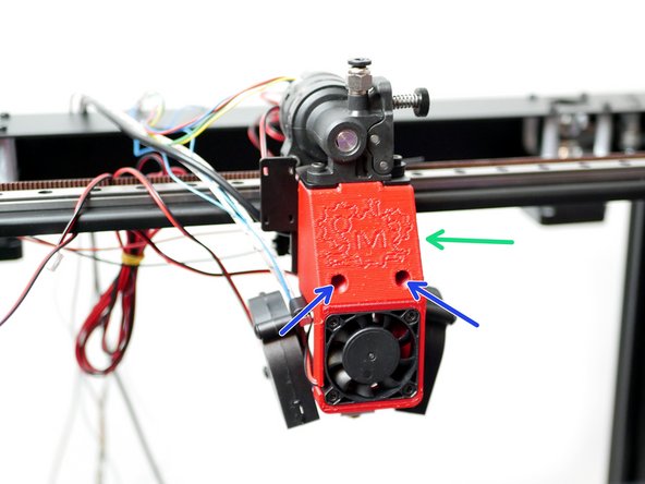
Begin by feeding the fans cable into the left side of the mount as shown.
-
Push the cooling fan mount assembly onto the metal mount.
-
Secure with two M3 x 20mm bolts. Avoid over tightening.
-
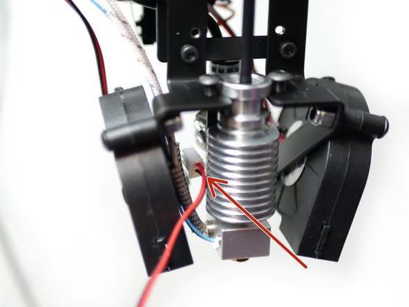
Before continuing, use a marker to mark the hotend cooling fan's connector, this will come in handy later when wiring.
-
-
-
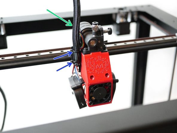
Use the braided sleeving to wrap the cables from the tool head.
-
Use two cable ties to secure it to the hotend mount as shown.
-
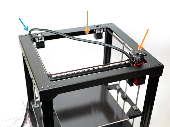
Extend the tool head to the bottom right corner.
-
Secure the other side of the cable loom to the rear of the printer.
-
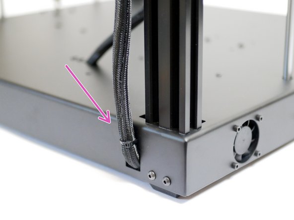
Feed all of the cables into the base. Fix the loom to the base with cable ties.
-
The Orbiter cable is short, but included is a black extension cable, use this to reach the control board.
-
-
-
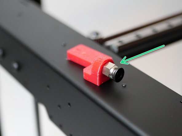
Take the filament sensor mount and fix to it the PC4 Coupling. The coupling can thread straight into it, you will need to use a pair of pliers to turn and secure it.
-
Secure it along with the filament sensor to the side of the printer.
-
You can secure it to either side of the printer.
-
M3 x 25mm Cap bolt
-
M3 Nyloc Nut
-
-
-
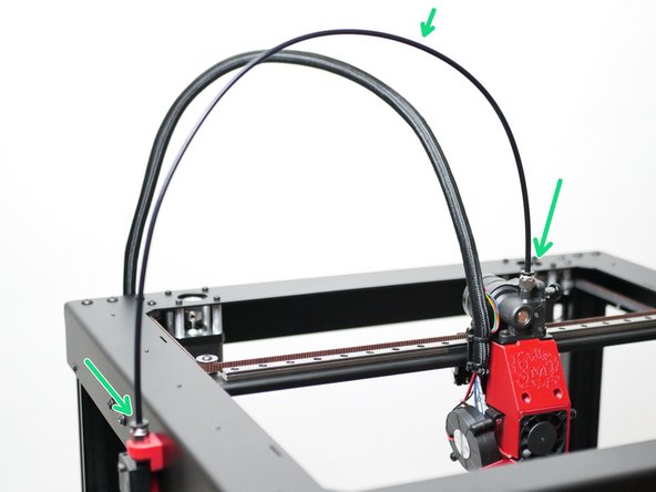
Finally, attach the PTFE tube from the filament sensor assembly to the Orbiter Extruder.
-
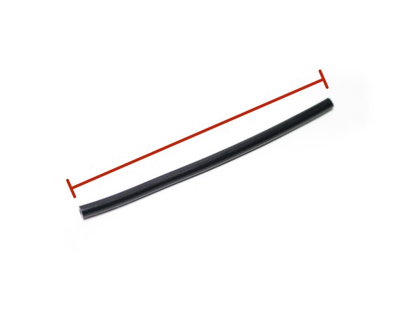
The length of the tubing should be approx 60cm.
-
Cancel: I did not complete this guide.
2 other people completed this guide.
2 Comments
I cut the tubing for run from the motor to the hotend to 3 1/2 inches (89 mm), which is very slightly too short - 3 9/16 (90.5 mm) would probably be better. The guide just shows “…” right now.
Greg Murnane - Resolved on Release Reply


