
-
-
The ProForge 5 is powered by Klipper Firmware which is an open source 3D printer firmware developed by the very talented Kevin O'Connor.
-
The Raspberry Pi 5 board is essentially a mini-computer. It is what runs Klipper and can be considered the "brain" of the 3D printer.
-
Alongside the Raspberry Pi board there are secondary control boards that also need firmware flashing to them:
-
The BigTreeTech (BTT) Octopus Pro is the printer's primary controller board. Acting as the "nervous system," it translates instructions from the Raspberry Pi into precise electrical signals that drive the motors, heaters, and sensors.
-
The SO3 Tool Board is a compact print head controller. On the ProForge 5, each tool head has its own board to independently manage its extruder, fans, and sensors.
-
The BTT Eddy Probe is a z-sensor that also needs firmware flashing to it.
-
In this stage we will flash these four firmware's - starting with the Pi.
-
-
-
Download the Klipper Firmware Image here.
-
Last updated 17/03/2026
-
Extract the .zip file after downloading. On Mac you can double click to do this, on Windows you can use WinZip.
-
-
-
To Flash the SD card you will need an image writing tool.
-
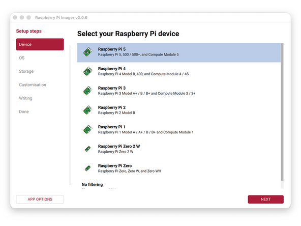
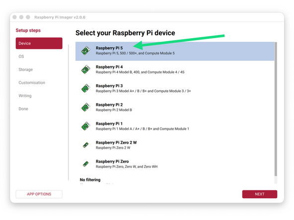
We recommend using the Raspberry Pi Imager.
-
To edit text files you will also need a text editor.
-
Windows: Notepad++
-
Mac/Windows: Sublime Text
-
-
-
Take the included 32GB SanDisk SD card and flash onto it the Klipper firmware image that you downloaded in the previous step.
-
Ensure that before flashing the firmware you have extracted the .IMG file.
-
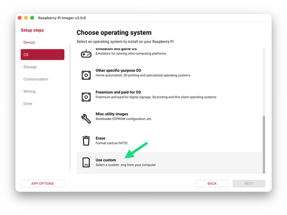
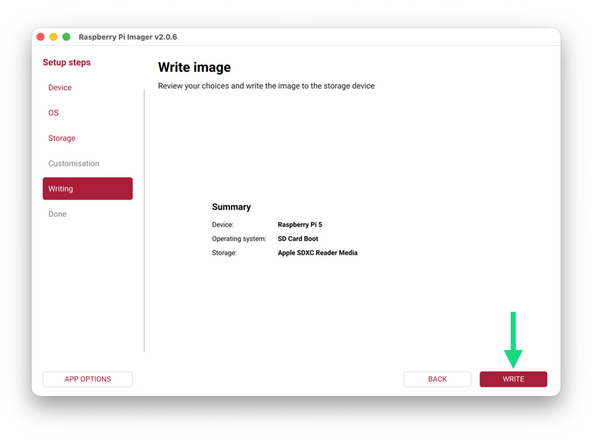
Use the Pi imager software to flash the .img file to the SD card.
-
Pi 5 -> Use custom -> Select the SD card -> WRITE
-
The process will take roughly 10min.
-
-
-
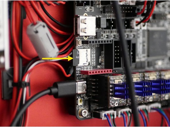
Insert the flashed SD card into the Raspberry Pi 5 board.
-
Inserting it can be fiddly, note that the printed side of the SD card faces away from you.
-
-
-
Download the firmware file for the Octopus Pro board here.
-
Copy the file onto the SD card included with the Octopus Pro board and re-insert it.
-
Do not copy this file onto the Pi's SD card.
-
-
-
Double check your wiring from the previous stage, especially +/- terminals.
-
Check that none of the cables are loose from their terminals.
-
Check the power supplies have their voltage input switches set to your mains voltage, 230V for Europe and 110V for North America.
-
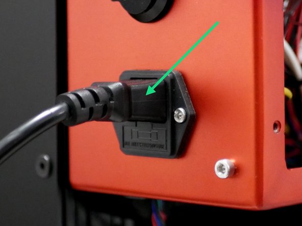
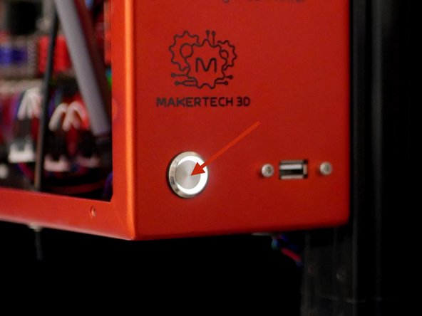
When happy plug the cable into the back of the printer and push the switch at the front to power up.
-
Do not touch the connection terminals, plug port or inside of the switch when the power cord is plugged in!
-
-
-
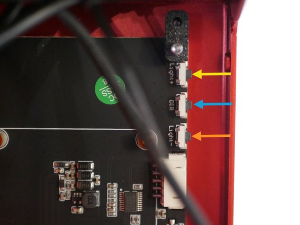
If the display is not showing an image check that the brightness is not all the way down.
-
Brightness Up
-
Brightness Down
-
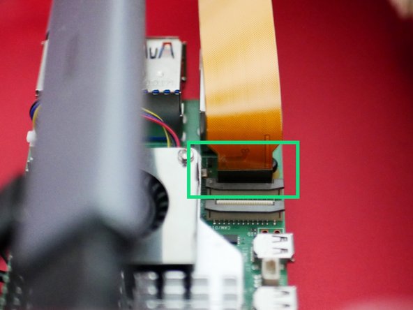
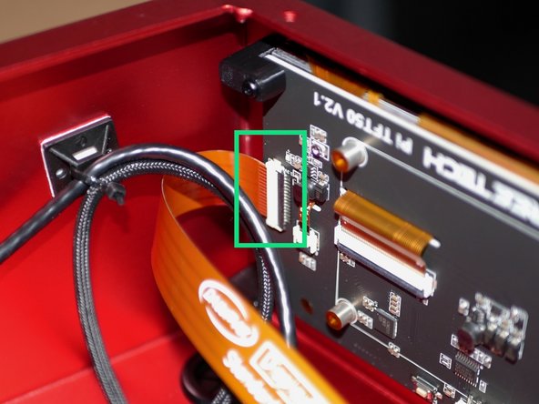
If the display is still not showing an image check that the ribbon cable is correctly installed.
-
If the display is upside down, rotate it by pressing this button.
-
If the display is still not booting see the next few steps for troubleshooting.
-
-
-
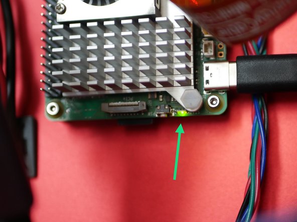
Near the SD card is an indicator LED, it will blink in a distinctive way to indicate an error.
-
See the error list here.
-
Known Issue: LED blinks 3 slow pulses followed by 1 fast one.
-
Bootloader is corrupt or missing and needs re-flashing, see next step.
-
If your status LED indicates something different please contact us for support at info@makertech3d.com
-
-
-
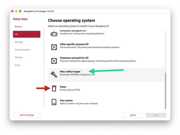
Take a separate SD card (1gb or more) and plug it into your computer. If you do not have a seperate card you can use the included 32GB card, but format it to FAT32 first.
-
The Pi imager software can also be used to format cards.
-
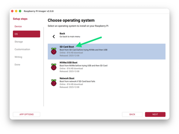
Use the Raspberry Pi Imager and navigate:
-
Raspberry Pi 5 -> Misc Utility Images -> Bootloader (Pi 5 Family) -> SD Card Boot
-
Select your target SD card and WRITE.
-
Once complete, take the SD card and plug it back into the Pi, the LED on the Pi should flash multiple times to indicate the Bootloader has been flashed. Power down after around a minute.
-
Replace the SD card with your firmware image card and that should fix the problem. Or format and reflash the card if you used the same one.
-
-
-
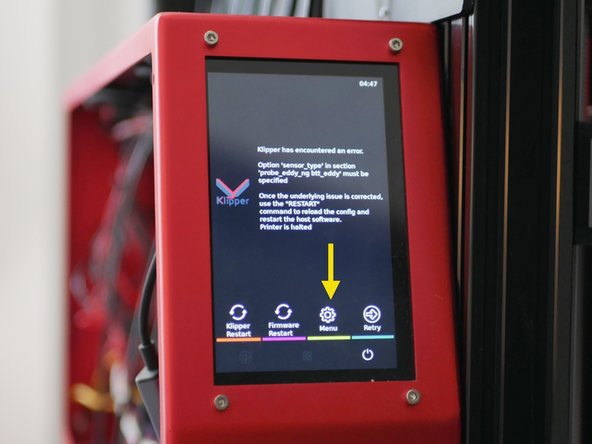
Ignore any errors at this stage.
-
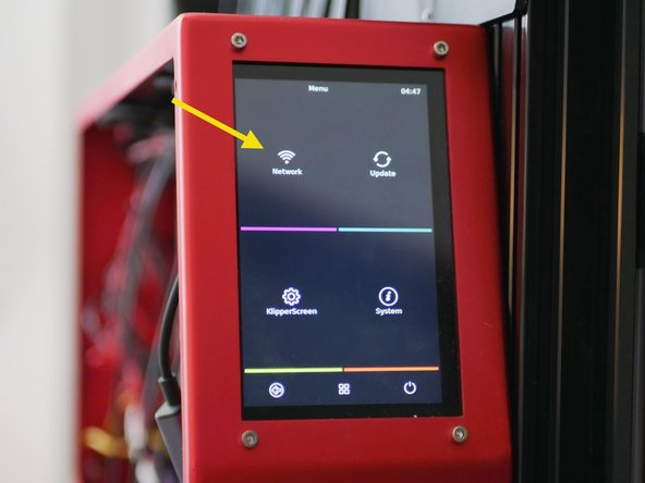
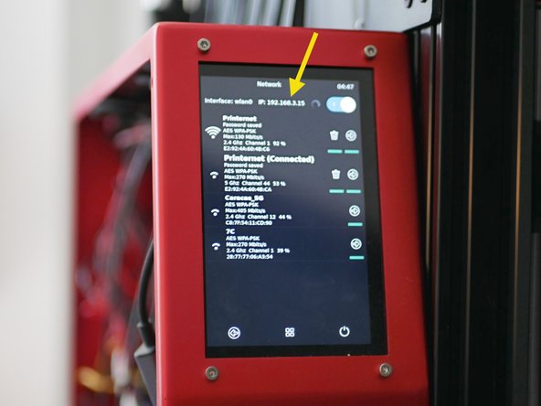
Use the touch screen to navigate to WiFi settings and connect the ProForge 5 to your local network.
-
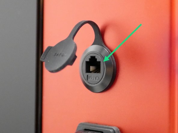
Alternatively you can also connect via the ethernet port.
-
-
-
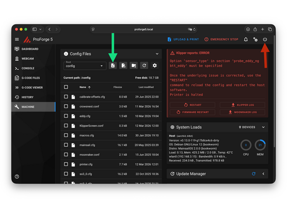
Mainsail is the browser interface for the Proforge 5.
-
It can be accessed by going to a browser on a device that is connected to the same network as the printer and entering proforge5.local
-
Restart the printer if you can't connect via proforge5.local. Restart your network router if you're still having trouble.
-
You can also connect by entering in the printers ip address which can be found in the networks setting page on the touch screen.
-
-
-
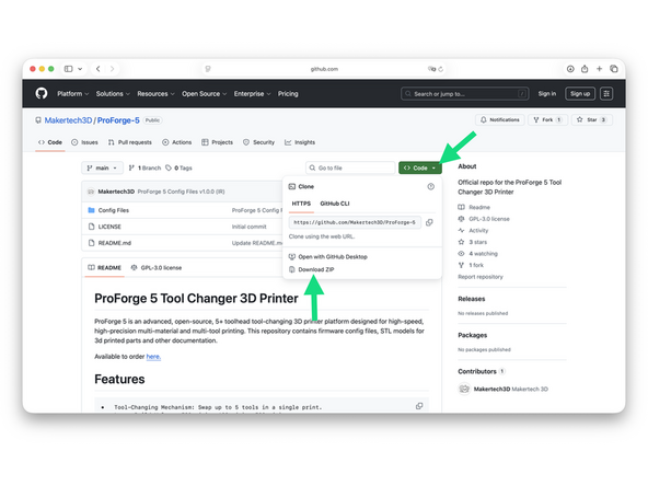
The latest ProForge 5 config files can be found here.
-
v1.0.0 (IR) is what can be found preloaded on the firmware image previously downloaded.
-
Updates:
-
We advise creating a GitHub account and following our repository to get notified every time there is an update to a config file.
-
-
-
Upload all of the downloaded config files to your printer, replacing any duplicates.
-
Once uploaded restart klipper by pressing the power button in the top right and then restart.
-
-
-
Firmware for the various control boards is created using the Pi:
-
Octopus Pro (recreate if there's an mcu error)
-
Eddy Probe
-
Print Heads
-
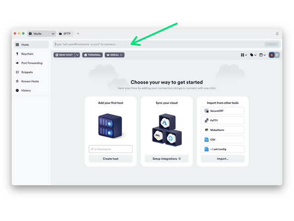
In order to access the Pi we will use a software called Termius.
-
-
The free version of the software is enough for what we need to do.
-
-
-
Install Termius and run through the set up wizard until you reach this dashboard.
-
In the text bar at the top type in the following:
-
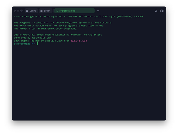
ssh pi@proforge5.local OR ssh pi@<your printers ip address>
-
The default username is pi and password is admin
-
-
-
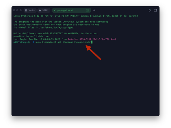
A list of timezone names can be found here:
-
-
Use the following command with your timezone at the end:
-
sudo timedatectl set-timezone <your timezone>
-
Timezone names are case-sensitive
-
The default password is admin
-
Note that when typing the password it will not display the characters, after typing hit enter to continue.
-
You can confirm it with this command: timedatectl
-
-
-
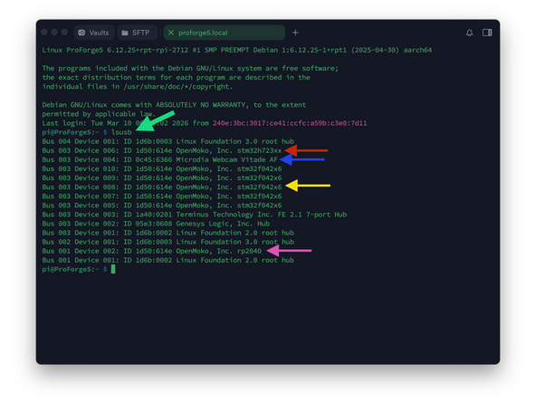
Send the command: lsusb
-
You should have:
-
Octopus Board: stm32h723xx
-
Camera: Microdia Webcam
-
Print heads: stm32f042x6 (one for each print head connected)
-
Eddy Probe: rp2040 (if missing continue)
-
If any are missing check the USB cable connection to the Pi.
-
-
-
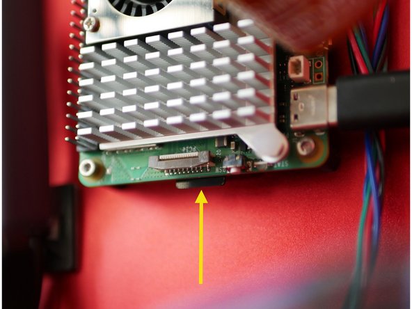
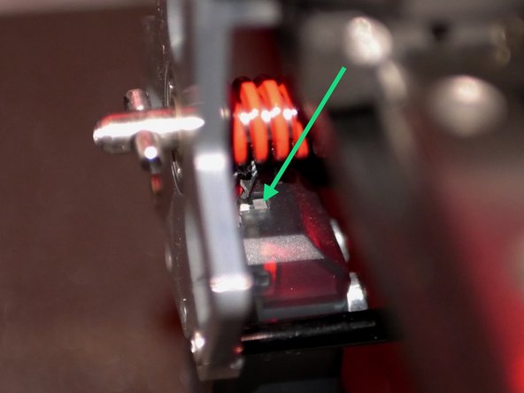
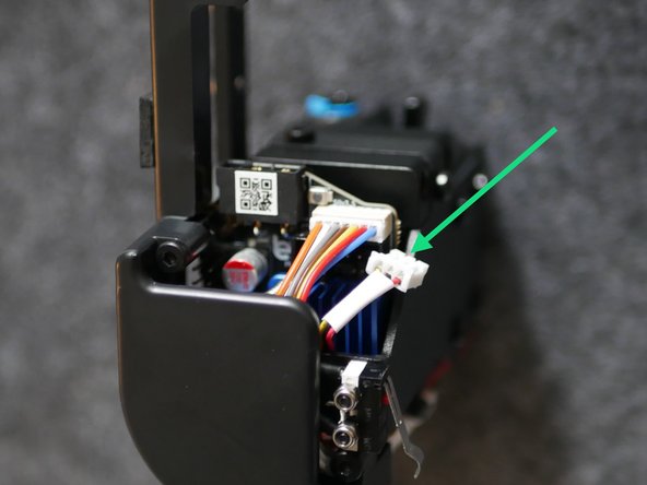
Before being able to flash the Eddy probe we need to put it in Boot Mode - this can be a little tricky and you may need a hand to help you with it.
-
Put Eddy into Boot Mode by:
-
With the printer powered up disconnect the Eddy USB cable and reconnect it whilst holding down the boot button.
-
You should be able to reach the button with a small Allen key.
-
-
-
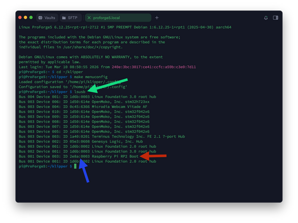
In Termius send the following command:
-
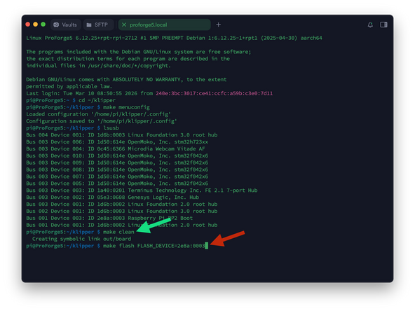
lsusb
-
It should return with the Eddy in Boot Mode.
-
Note the device ID, in our case 2e8a:0003
-
-
-
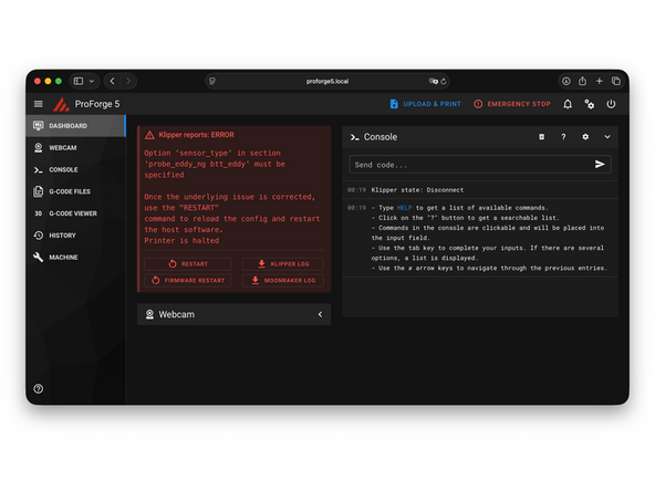
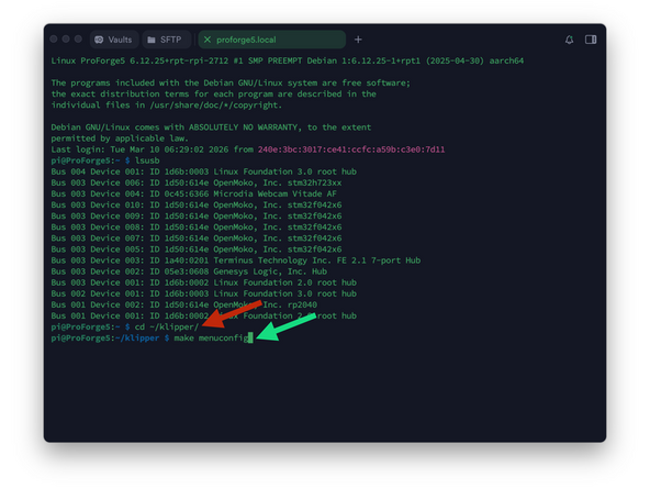
We'll start by flashing the Eddy Probe's firmware to remove the 'sensor_type' error.
-
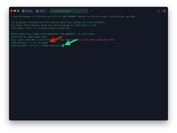
In Termius enter:
-
cd ~/klipper/
-
followed by:
-
make menuconfig
-
-
-
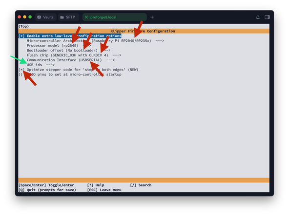
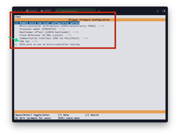
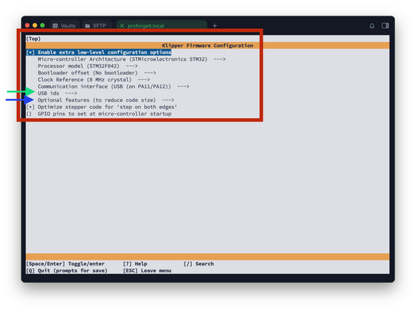
You should now see a config menu, use the arrow keys (up and down to scroll, left and right to enter and exit menus) on your keyboard to adjust the options. Match the options as shown here.
-
Make sure all settings match as shown in the image to avoid errors and unexpected behaviour.
-
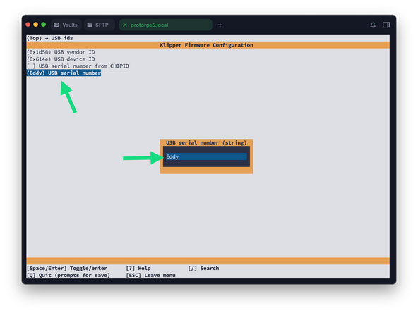
Set the USB serial to Eddy
-
When done, press Q and then Y to save.
-
-
-
Send the following command:
-
make clean
-
make flash FLASH_DEVICE=2e8a:0003
-
Where 2e8a:0003 is your device ID from the previous step.
-
Default pi password is admin
-
Note that when typing the password it will not display the characters, after typing hit enter to continue.
-
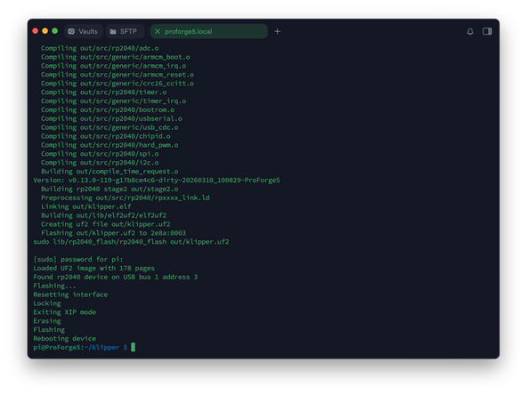
It should take a minute to flash. You may get a failed to reboot error - ignore this and manually reboot the Eddy probe by unplugging and plugging it back into the Pi.
-
-
-
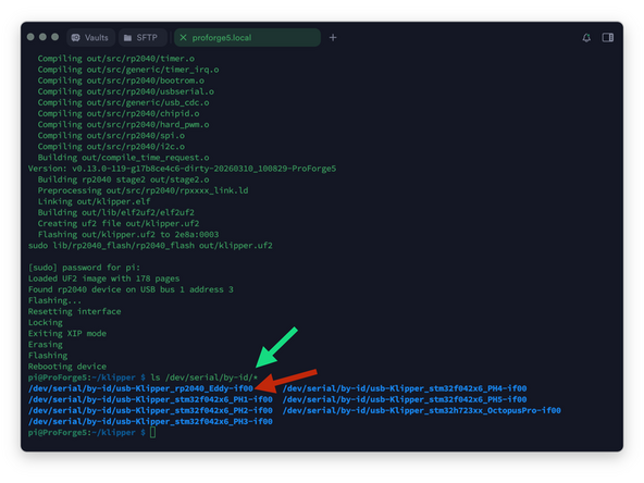
Send the following to find the Eddy Probe's Serial ID:
-
ls /dev/serial/by-id/*
-
Copy the Eddy's Serial ID to your clipboard.
-
-
-
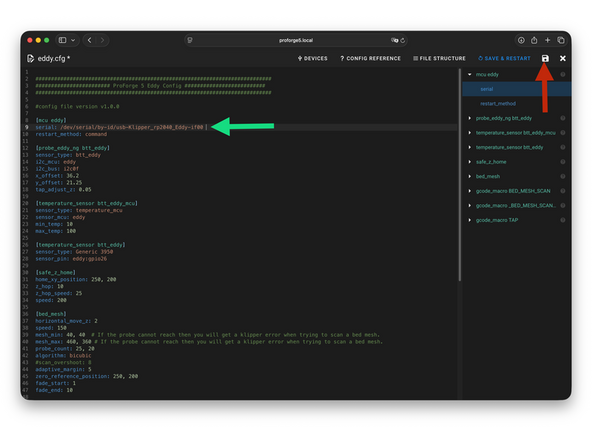
Insert the Serial ID into the Eddy.cfg file.
-
Make sure it is in the same format as shown.
-
Save when done.
-
-
-
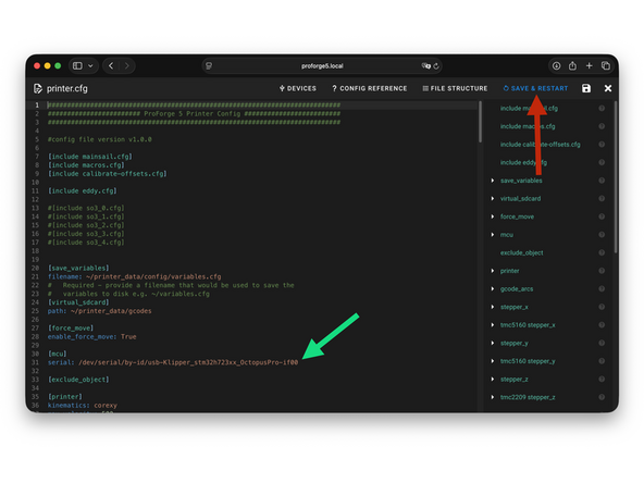
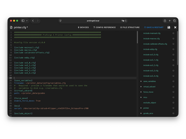
In printer.cfg remove the # from in front of [include eddy.cfg]
-
SAVE & RESTART when done.
-
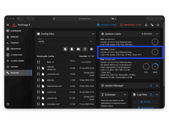
After restarting you should see the Eddy Probe connected and the 'sensor_type' error resolved.
-
If you get an mcu 'eddy' error double check the serial id and repeat the flashing process if necessary, again double checking the firmware settings are entered as shown in the previous steps.
-
See next step if you get an mcu 'mcu' error.
-
-
-
An mcu 'mcu' error means the Pi is unable to connect to the Octopus Pro board.
-
The first thing to check is the USB connection. Check that it's secure on both ends. Try plugging it directly into the pi and not the hub. You can also try a different cable. Restart the printer to check.
-
If the error persists format the SD card on the Octopus Pro board and copy the firmware.bin file to it again. Insert it back into the octopus pro board and power cycle the printer.
-
If you are still getting the error see the next steps for creating the firmware file from your Pi.
-
If you have a different error please contact us for support.
-
-
-
The following steps show how to create the firmware.bin file for the Octopus Pro board. If you did not get an mcu error you can skip the steps marked "Octopus Pro - ", and continue with the Print Head firmware.
-
Send the following commands to the terminal:
-
cd ~/klipper/
-
followed by:
-
make menuconfig
-
-
-
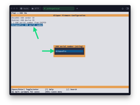
You should now see a config menu, use the arrow keys on your keyboard (left and right to enter and exit menus) to match the options selected in the image.
-
Double check your control board has the H723 chip.
-
Make sure all settings match as shown in the image to avoid errors and unexpected behaviour.
-
Set the USB serial to OctopusPro
-
When done, press Q and then Y to save.
-
-
-
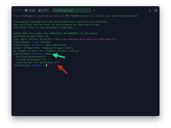
Send a make command to create the firmware file.
-
At the end of the process, you should have a klipper.bin file as shown.
-
-
-
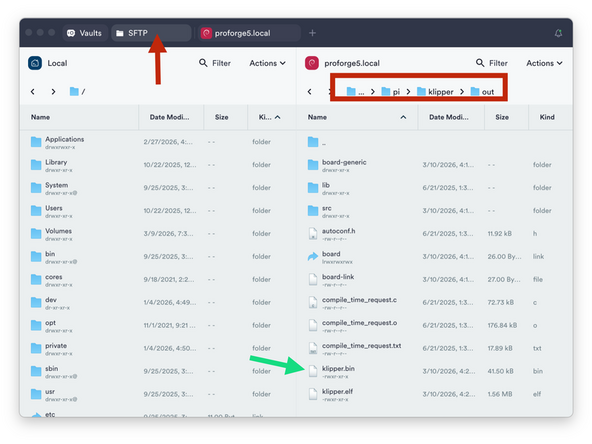
Go to the SFTP tab to access the folder directory on the Pi and navigate to:
-
home -> pi -> klipper -> out
-
Drag and drop the klipper.bin file to a folder on your computer using the window on the left side of the application.
-
-
-
Rename the klipper.bin file to firmware.bin
-
Take the micro SD card from the Octopus Pro board and copy onto it the firmware.bin file.
-
With the printer powered off:
-
Insert the SD card into the Octopus Pro board and power back on the printer to flash the board.
-
You may still get an mcu error, ignore for now.
-
-
-
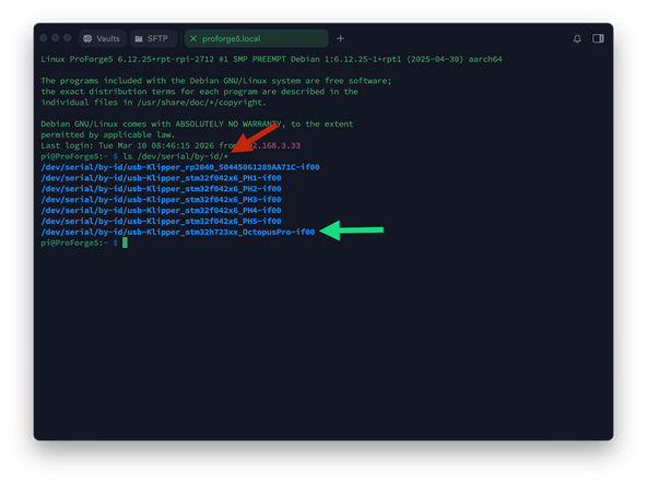
Use Termius to SSH back into the printer in order to retrieve the boards serial id.
-
Find your unique id by sending:
-
ls /dev/serial/by-id/*
-
Copy the Octopus Pro board id, it should have h723 and OctopusPro in its name.
-
-
-
In mainsail open the printer.cfg.
-
Paste the boards id in the mcu section.
-
SAVE & RESTART when done.
-
-
-
Before flashing the print heads unplug the fans from the print head tool board. This will make the print heads easier to handle when putting into DFU mode for flashing.
-
Power down the printer before unplugging fans.
-
-
-
After powering back up, reconnect to the printer via SSH in Termius and send:
-
cd ~/klipper/
-
Followed by:
-
make menuconfig
-
-
-
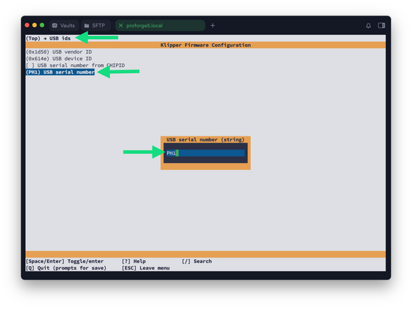
After opening the config menu, use the arrow keys on your keyboard to match the options selected in the image.
-
Set the USB id name to PH1
-
Print heads are flashed one at a time, PH1 is the first print head closest to the front of the machine. Subsequent print heads should be named PH2, PH3 etc.
-
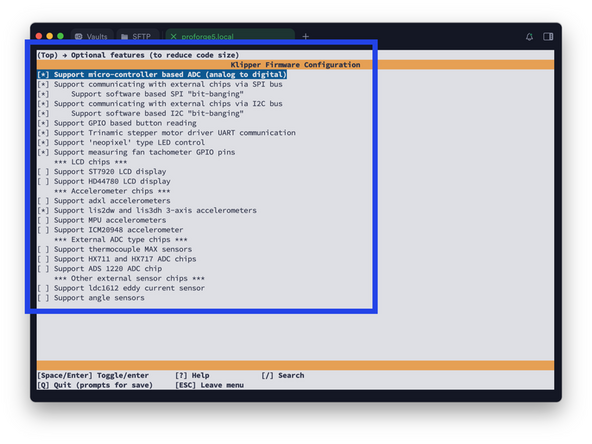
Set optional features according to the image.
-
When done, press Q and then Y to save.
-
Before exiting, thoroughly double check that the settings match as shown here, incorrect settings will cause errors.
-
-
-
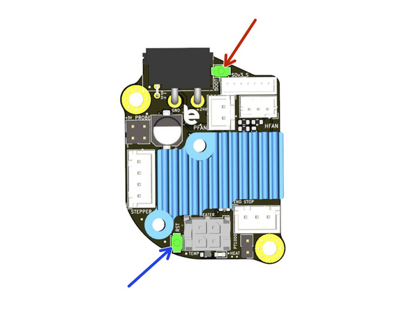
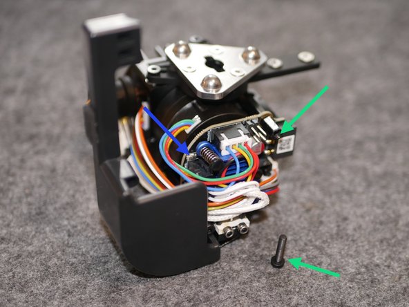
In order to flash a print head tool board we need to put it into DFU mode.
-
Hold down the the boot button.
-
With the boot button held down, press the reset button.
-
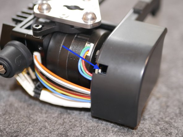
The tool board should now be in DFU mode, indicated by the white hotend LED near the nozzle.
-
The buttons might be a little tricky to access. Use a ceramic screwdriver or simple toothpicks to push the buttons to avoid creating any short over the board with metal tools.
-
If the reset button is proving tricky to reach remove one screw and swivel the electronics cover for easier access.
-
-
-
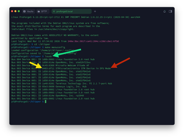
Verify DFU mode by sending this command:
-
lsusb
-
You should see the board in DFU mode.
-
If the board is not showing in DFU mode unplug and replug the HEXA USB hub board from the Pi. Wait a moment and check again by re-sending the lsusb command.
-
Note the ID, in our case 0483:df11
-
-
-
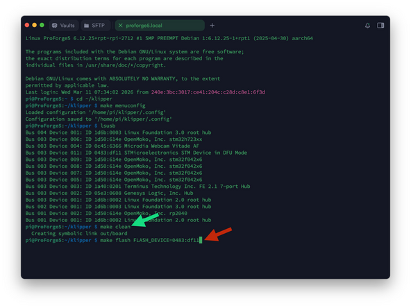
Run make clean to clean up the make environment
-
Followed by: make flash FLASH_DEVICE=0483:df11
-
Where 0483:df11 is your device ID from the previous step.
-
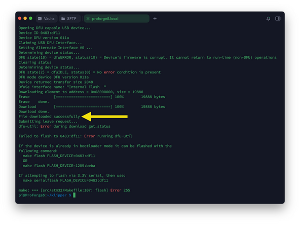
Pi default password is admin
-
Note that when typing the password it will not display the characters, after typing hit enter to continue.
-
It should take a minute to flash. You may get an error - ignore this. As long as you have a File downloaded successfully response the board has been flashed.
-
-
-
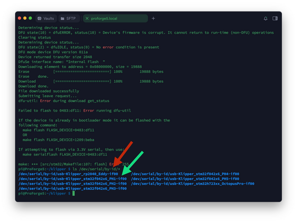
Send the following to verify that the print head has been flashed:
-
ls /dev/serial/by-id/*
-
The ID changing to PH1 indicated that flashing was successful.
-
ID's marked PH2, PH3 etc. being subsequent installed print heads.
-
If the ID name does not change to include PHx then flashing has failed and the step should be repeated.
-
-
-
Go to Printer.cfg and remove the # from in front of the config files that have been flashed.
-
If there is a print head that you do not have installed then leave its # in place or else you will get an error.
-
SAVE & RESTART
-
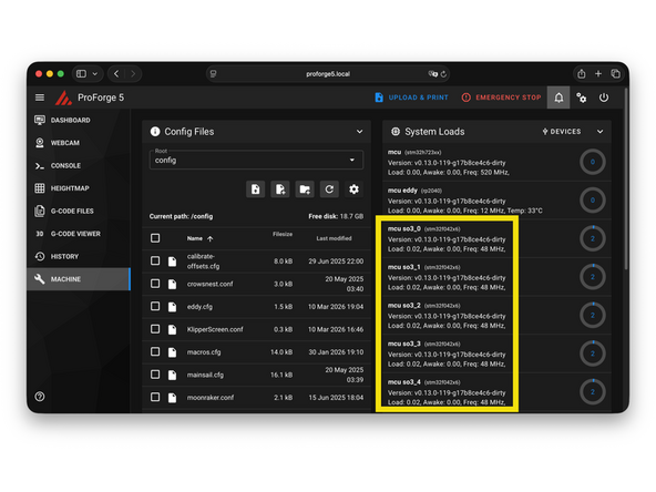
If flashed successfully they should show up here after restarting.
-
-
-
Repeat from step 34 to flash the remaining print heads.
-
Make sure to label print heads according to their docking order from front to rear - PH1 to PH5.
-
Install print heads from the front to the rear without skipping a slot.
-
-
-
If you only have the default SO3 extruders installed this step can be skipped.
-
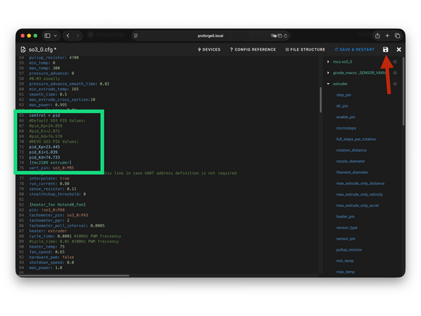
Open each SO3_x.cfg file and scroll to the PID settings.
-
If using a REVO head comment out the SO3 PID values by adding a # in front of the line and enable the REVO PID values by removing the #.
-
Save the configuration file.
-
Restart the printer after modifying all print head config files.
-
-
-
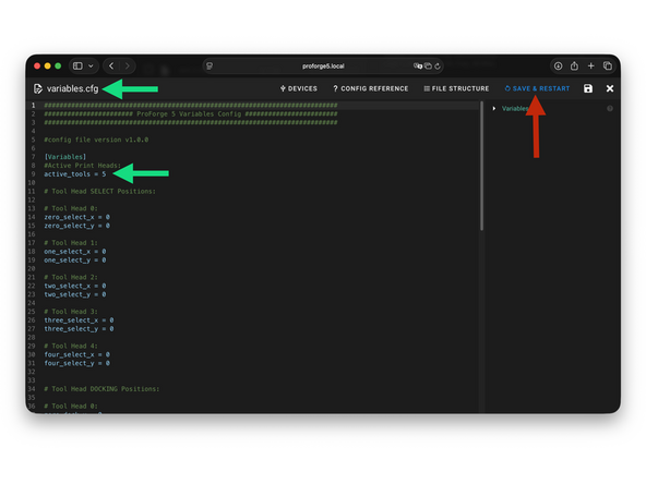
In the Variables.cfg file set the number of active print heads.
-
If you have just one print head installed set the value to 1, and so on.
-
Save when done.
-
-
-
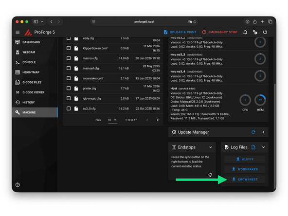
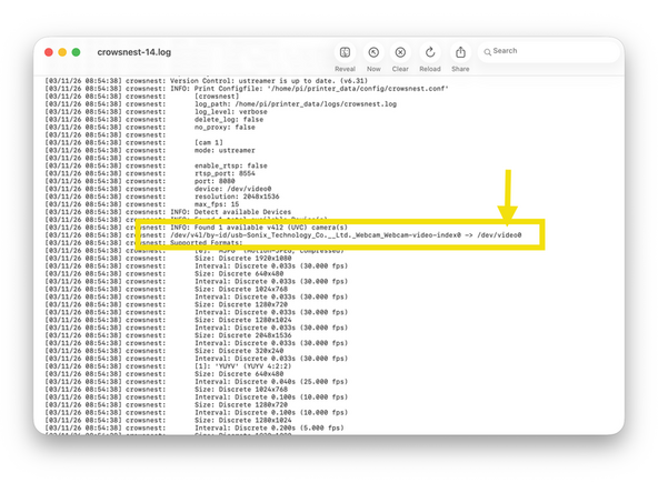
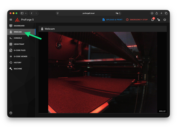
Check the cameras device ID in the Crowsnest log file.
-
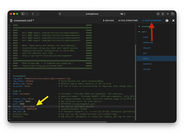
Set device ID to what you found in the Log file, in our case:
-
/dev/video0
-
Save and restart when done.
-
-
-
If you have the enclosure upgrade activate it by removing the # in front of [include enclosure.cfg].
-
SAVE & RESTART when done.
-
-
-
If you're getting an error you may need to re-flash the indicated board.
-
If you're still stuck you can get support via the Facebook Group, Discord Server or emailing us at info@makertech3d.com
-
For klipper related issues Google/Ai can also be a good resource as klipper is an open-source firmware with a large user base.
-


![In printer.cfg remove the # from in front of [include eddy.cfg]](https://d3t0tbmlie281e.cloudfront.net/igi/makertech-3d/aByn3ARNtACJvXnB.medium)


![If you have the enclosure upgrade activate it by removing the # in front of [include enclosure.cfg].](https://d3t0tbmlie281e.cloudfront.net/igi/makertech-3d/ZTCLcNRNdKGZqnMr.medium)
Cancel: I did not complete this guide.
6 other people completed this guide.
