
Parts
No parts specified.
-
-
Fix the lead screw nut onto the gantry.
-
Three M3 x 10mm bolts
-
Three M3 nyloc nuts
-
Orientate as shown, with the long side facing up.
-
-
-
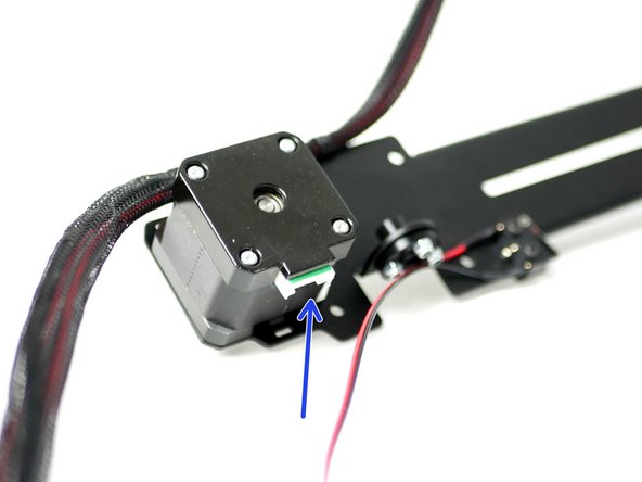
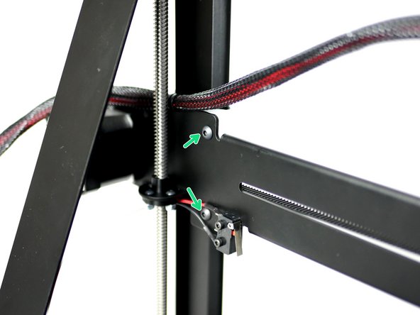
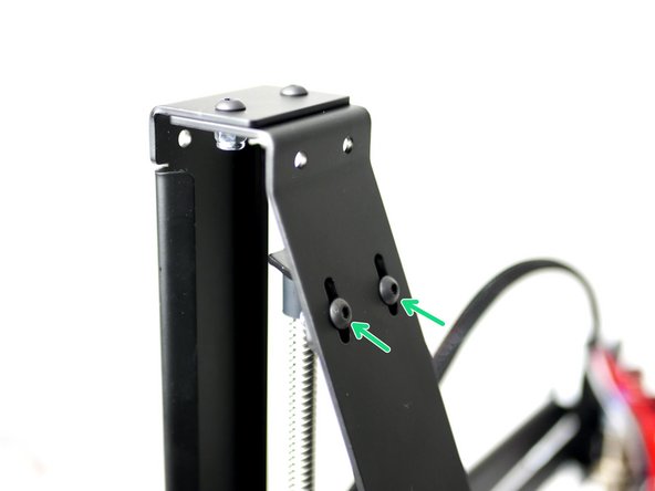
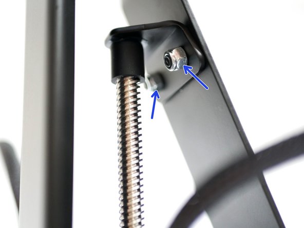
Take the remaining end-stop and fix it to the gantry.
-
Two M2.5 x 12mm bolts
-
Two M2.5 nyloc nuts
-
Match the orientation of the switch as shown in the image.
-
-
-
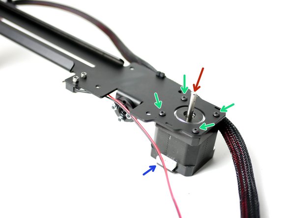
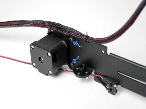
Fix a NEMA 17 motor onto the gantry.
-
Four M3 x 6mm bolts
-
The motors cable connector should face down.
-
The shaft should be on the back of the gantry.
-
-
-
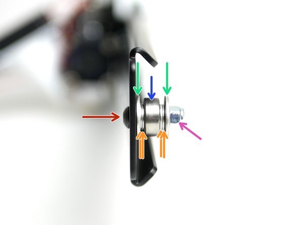
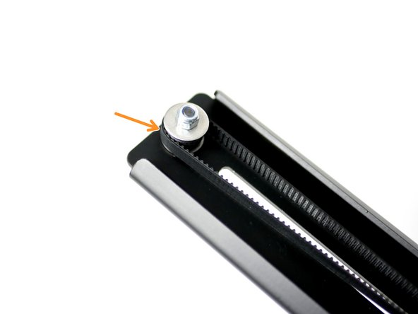
Assemble the Y-idler at the end of the gantry.
-
M4 x 18mm bolt
-
Two M4 penny washers
-
Four M4 washers
-
624zz Bearing
-
M4 nyloc nut
-
Fasten tight, but make sure that the bearing can still spin.
-
-
-
Take the remaining GT2 belt and tie one end to the left bolt on the tool carriage.
-
Make sure that the belts teeth are facing inwards.
-
Tie firmly with two cable ties.
-
Keep excess belt to approx 0.5CM.
-
-
-
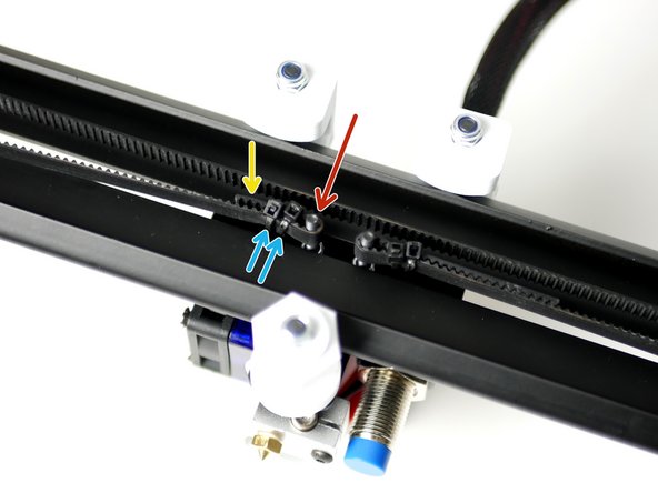
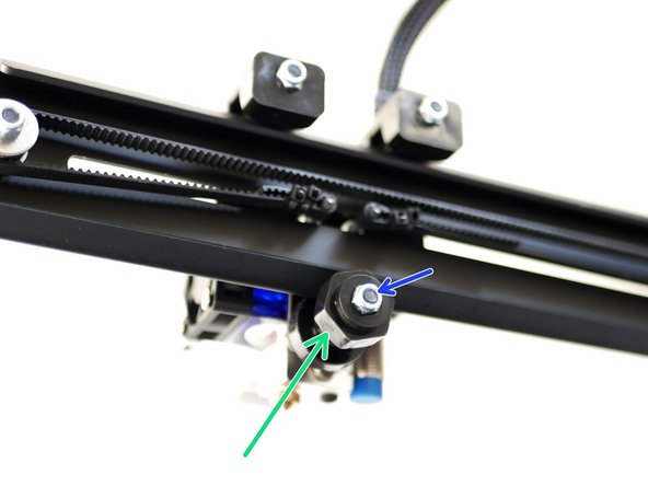
Wrap the belt around the idler making sure that the teeth are on the inside of the loop.
-
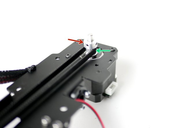
Slide a pulley onto the shaft of the motor, orientating like shown, but don't fasten the grub screws yet.
-
Wrap the belt around the pulley too.
-
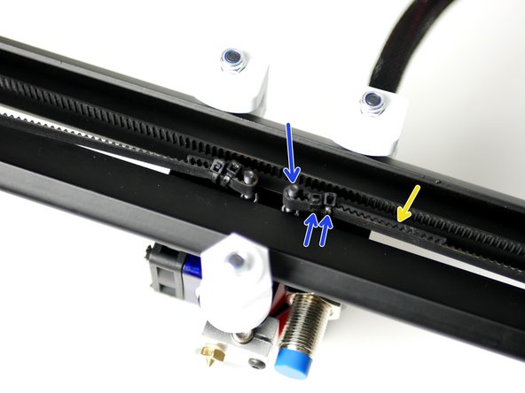
Pull the belt around the bolt, do so tightly and use a bulldog clip to hold in place temporarily. Or ask some one to hold the belt together with a pair of pliers.
-
Firmly cable tie the belt to the tool carriage, leaving approx. 1 inch of excess belt.
-
We recommend that the belt be "guitar string tight". Too tight or too loose and print quality will be affected. If in doubt, tighter is usually better, but if you start warping the metal or bending the motor shaft, you've gone too far.
-
-
-
Rotate the eccentric guide to get a good hold onto the gantry's rail.
-
Rotate the pulley by hand to move the print head.
-
The print head's movement should be straight and with out any wobble.
-
When happy with the print heads motion, firmly tighten the bolt holding the eccentric guide. You will need to pull the hotend out of the carriage to access the bolt.
-
-
-
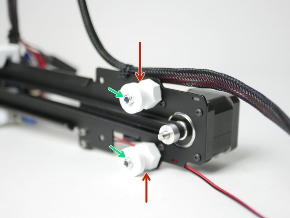
Fix two eccentric guides to the rear of the gantry like shown.
-
Eccentric guide
-
M4 x 30mm bolt
-
M4 nyloc nut
-
-
-
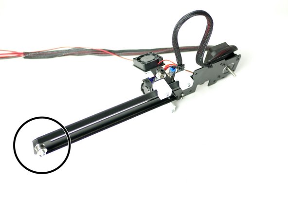
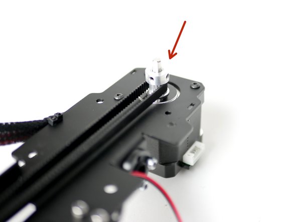
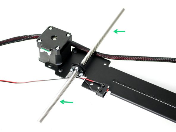
Thread the lead screw onto the nut, going about half way.
-
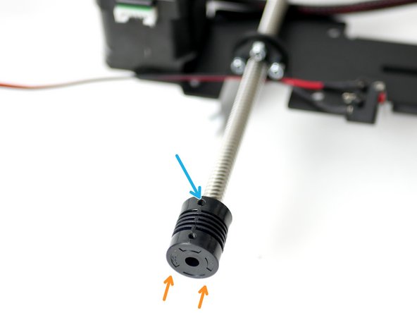
Fix to the bottom of the lead screw the 5x8 coupling.
-
Push the coupling on all of the way.
-
Tighten the grub screws firmly.
-
-
-
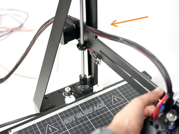
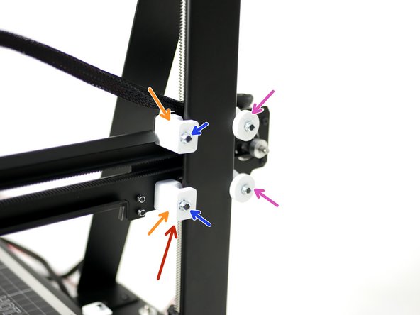
Fix the gantry into position like shown with the eccentric guides against the back of the z-pillar rail.
-
Slot the open end of the coupling onto the shaft of the z-motor.
-
Do not tighten any of the screws on the coupling yet.
-
-
-
Install the remaining fixed guides to the gantry.
-
Fixed guide
-
M4 x 30mm bolt
-
M4 nyloc nut
-
Tighten the fixed guides firmly.
-
Adjust the Eccentric Guides to get a tight grip on the pillar rails, you should still be able to move the gantry up and down by turning the lead screw. Once happy tighten the eccentric guides firmly.
-
You may have an eccentric guide left instead of a fixed one, this is OK, just use one of the eccentric guides here instead of fixed. Just make sure that when your adjusting it that the gantry arm is kept as straight and parallel to the platform as possible.
-
Make sure that you install the eccentric guide on this spot, else the tool carriage will bump it and not reach the endstop.
-
-
-
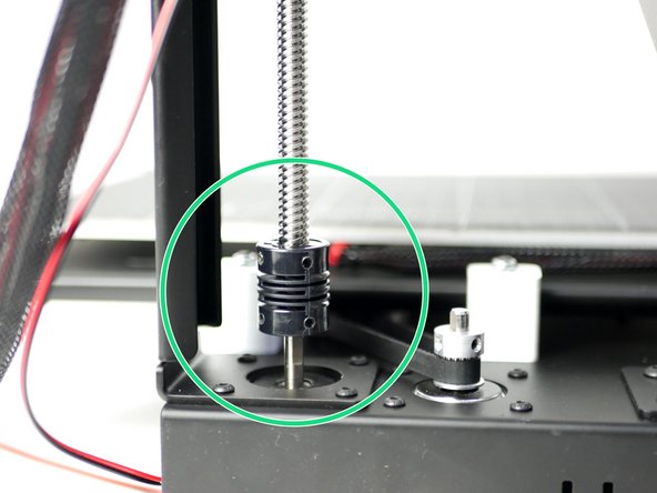
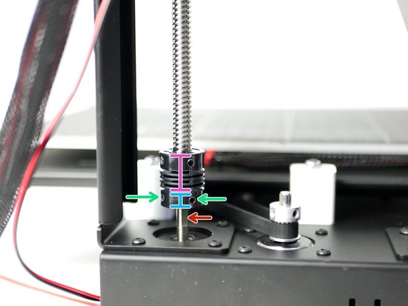
Secure the coupling onto the z-motor shaft by tightening the two grub screws.
-
Make sure that one of the grub screws is being tightened against the flat of the motors shaft.
-
Note, the end of the motors shaft should be pressing against the end of the lead screw, inside the coupling.
-
Important:
-
The lead screw inside the coupling.
-
The motor shaft inside the coupling.
-
There should be not gap between the lead screw and motor shaft.
-
-
-
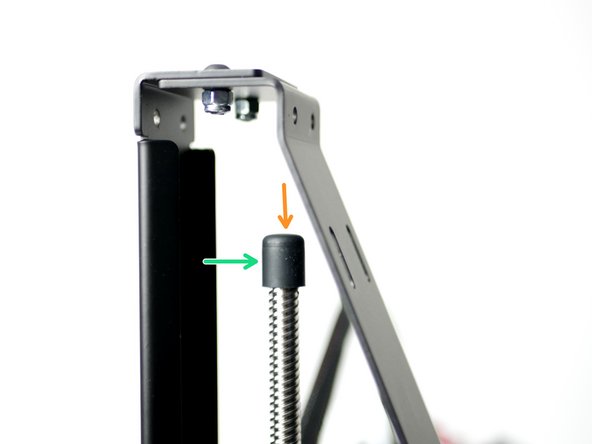
The lead screw top and bracket are optional but recommended. They were designed to improve layer resolution and hence print quality by keeping the lead screw fixed vertically.
-
Push onto the top of the lead screw the silicone cap.
-
Add a drop of dry lubricant or cooking oil to the top of the cap.
-
-
-
Fix the lead screw bracket to the support beam.
-
Make sure that it is pressing on top of the lead screw cap when secured.
-
M4 x 10mm bolt
-
M4 nyloc nut
-
Fix the bracket as flat as possible, if installed at an angle it will create z-wobble in the print.
-
-
-
Manually rotate the lead screw moving the gantry up and down, if there is any binding/bouncing of the gantry or stretching of the coupling then the bracket isn't pressed down on the lead screw enough or there is a gap between the lead screw and motor shaft inside the coupling.
-


Cancel: I did not complete this guide.
20 other people completed this guide.
