-
-
Download the two part DSH calibration model here.
-
Open your preferred slicing software. We will be using CURA.
-
-
-
Load the included DSH Calibration Model model into CURA.
-
There are two files, you will need to load both.
-
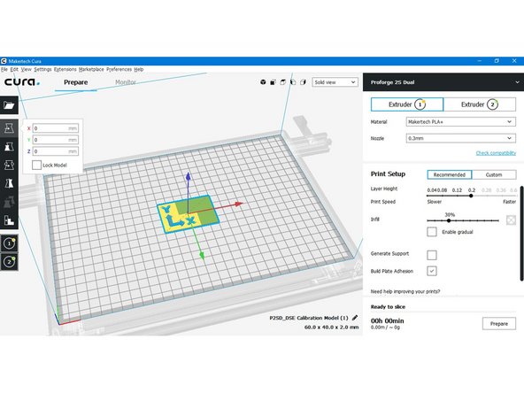
Align the models so that the arrows are in the direction of the axes.
-
Right click on this part of the model and choose Hotend #2.
-
-
-
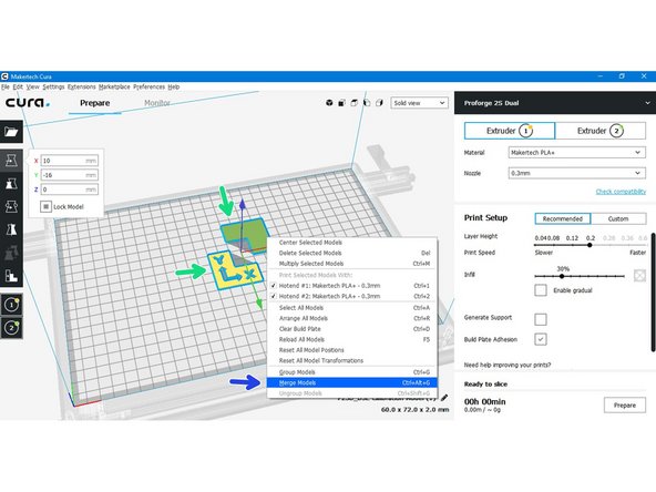
Hold shift and select both parts of the model.
-
Right click on either model, click on Merge Models.
-
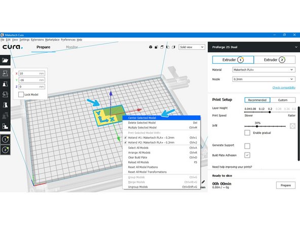
Right click on the single model and click on Center Selected Model.
-
-
-
Set the Hotends temperatures based on the materials you're loading into the Switching Hotend.
-
Remember that the low temp side is limited to 250C and the high temp side is limited to 400C.
-
-
-
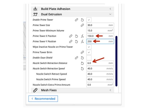
In Cura's Dual Extrusion setting, turn on the prime tower.
-
Set up as shown in the image.
-
Set the prime tower in a rear-central location on the bed. This is so the PTFE tube isn't being pushed one way or the other which could prevent switching.
-
Retraction between switches is important, we've set the default value to 6mm but you may need less or more here depending on the length of your bowden tube. When working with bowden extruders it's best to start with a small value here and work up, too high a value from the beginning can cause the hotend to clog.
-
-
-
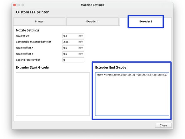
Enter the following bits of g-code into the printer settings end g-code box for both extruders (CURA):
-
Extruder 1 End G-code:
-
G0 F20000 X{prime_tower_position_x} Y{prime_tower_position_y}
-
Extruder 2 End G-code:
-
G0 F20000 X{prime_tower_position_x} Y{prime_tower_position_y}
-
-
-
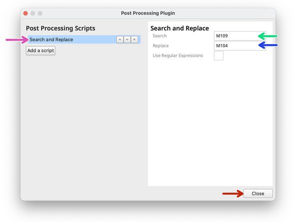
Go to Extension -> Post Processing -> Modify G-code
-
Click on search and replace.
-
Search for M109
-
Replace with M104
-
Hit close to save.
-
This script removes the waiting for temperature pauses between switches.
-
-
-
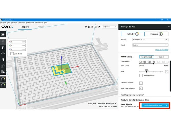
Hit prepare to slice the model.
-
Save it to an SD card.
-
-
-
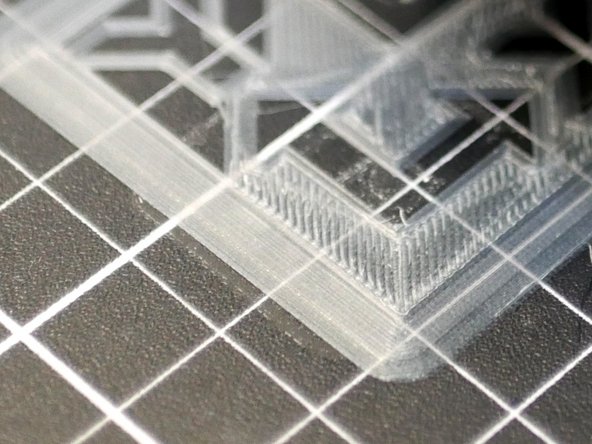
Check your first layer. It should look similar to this. (This may be a little too close, but closer is better than too far away).
-
Adjust your hotend offset as required.
-
-
-
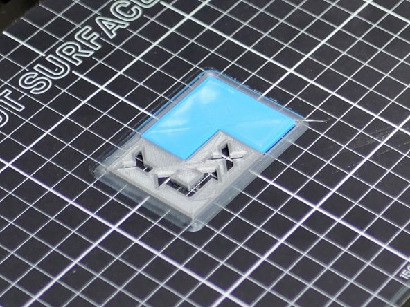
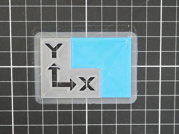
When finished, your calibration print should look similar to this. You may find that the two models may not be aligned perfectly.
-
We will fine tune this in the next step.
-
-
-
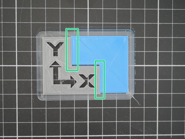
The calibration print should self align. The DSH is CNC machined to a high degree of precision. If you find gaps or overlaps in your print, we recommend first investigating that everything is OK mechanically.
-
If everything is mechanically OK, then we will adjust the X/Y offsets in Cura with the aim of getting the two parts to line up.
-
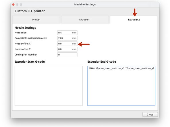
Offsets are entered in Machine Settings under the Hotend #2 Tab.
-
-
-
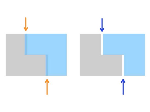
Overlapping in X Direction:
-
Decrease/Negative X-Offset
-
Gap in X Direction:
-
Increase/Positive X-Offset
-
In our case the print was fine in the X-Direction, so we left our X-offset as 0.
-
For example, if there had been a gap of 0.25mm, our offset would have been 0.25mm.
-
An overlap of 0.25mm would have meant an offset of -0.25mm.
-
-
-
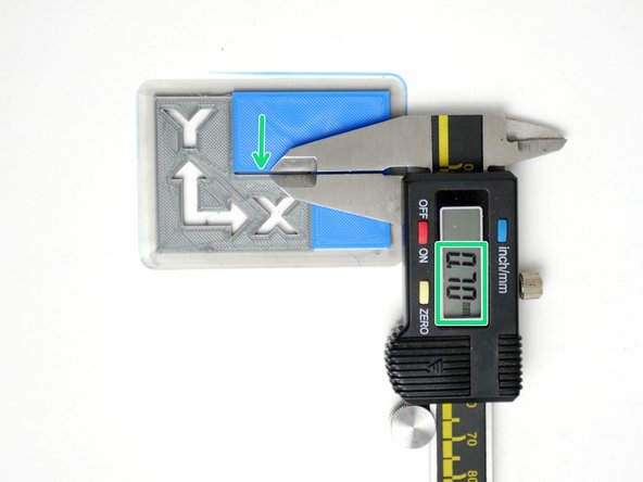
Overlapping in Y Direction:
-
Decrease/Negative X-Offset
-
Gap in Y Direction:
-
Increase/Positive X-Offset
-
In our case the print had a gap in the Y Direction, so we set our Y-offset to 0.7mm.
-
If there had been an overlap of 0.7mm, our offset would have been -0.7mm.
-
-
-
Re-slice the model in Cura and copy it onto the SD Card.
-
Congratulations! After printing the model again with the dialled in offsets you should have the DSE all setup.
-