-
-
Carefully open the box from the top, as indicated by the "This Way Up" labels.
-
Remove the top layer of packaging.
-
Remove the enclosure panels.
-
Remove the foam from the sides of the box.
-
Picking it from the sides, pull the printer out of the box.
-
-
-
Depending on your configuration, you should have the following:
-
Proforge 3D Printer
-
Lead Screws and Couplings. (These are disassembled in recent assemblies to prevent damage to them)
-
A box containing the following: Touch Screen, SD Card, Spool Holder, Power Cable, Hotend Cover.
-
Dual Switching Hotend Config: Two Extruders, Direct Drive Assembly, Direct Drive Accessories Bag.
-
Enclosure: Enclosure Panels, Enclosure Roof, Fume Filter, Fasteners.
-
OctoPi: 4GB SD card, Blue USB Cable, White USB Cable
-
-
-
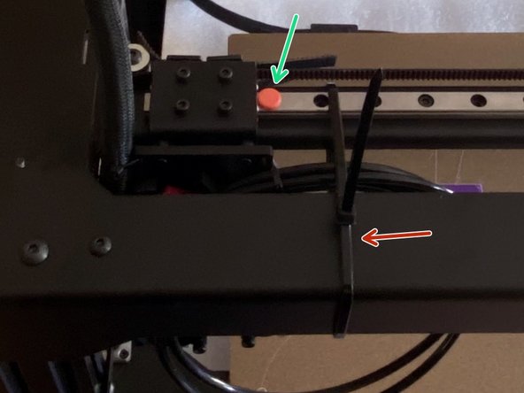
Cut the cable tie holding the gantry.
-
Also remove the orange stopper.
-
Cut the cable ties holding the bed down also.
-
-
-
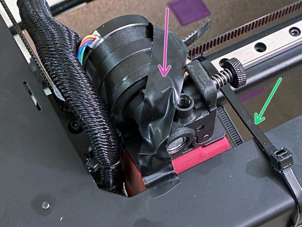
Cut the cable tie and remove the orange stopper from the rail.
-
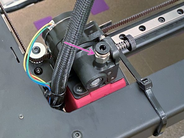
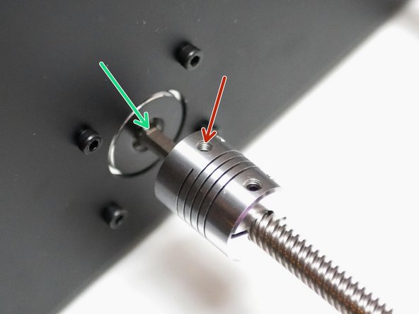
Remove the tape from the print head and fix the coupling onto the extruder.
-
-
-
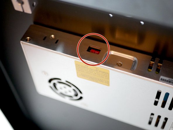
Place the printer onto its side and check that the power supply is set to your mains voltage.
-
Incorrectly setting this and powering on could damage your PSU.
-
-
-
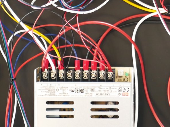
Double-check the wiring in general in case anything has come loose during shipping.
-
Especially double-check the terminals on the power supply. They should all be firmly tightened down.
-
Wiring Diagram
-
-
-
-
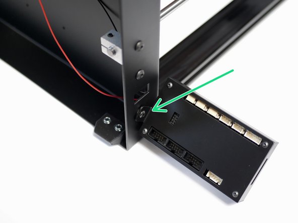
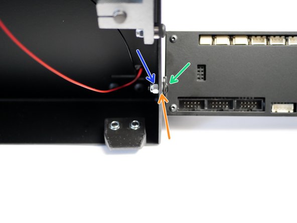
Attach the touch screen case assembly to the bottom left of the base of the printer as shown.
-
M4 x 10mm bolt
-
M4 Washer
-
M4 Nyloc
-
-
-
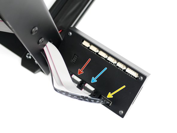
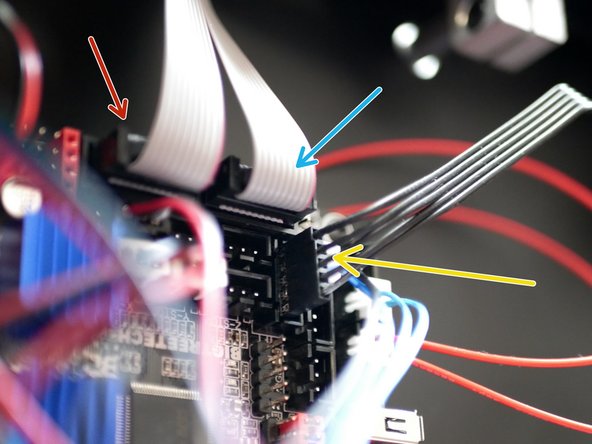
Black cable: This is for controlling the printer through the touch screen interface via serial.
-
The two white cables are for controlling the printer directly via marlin's interface through emulation mode.
-
EXP 1
-
EXP 2
-
Black cable - board side.
-
Note the orientation of the loose connector and the 4-pin connector, match as shown in the third image.
-
-
-
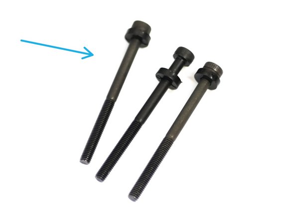
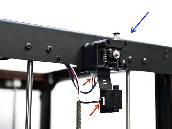
Take these three bolts and remove them from the back of the extruder.
-
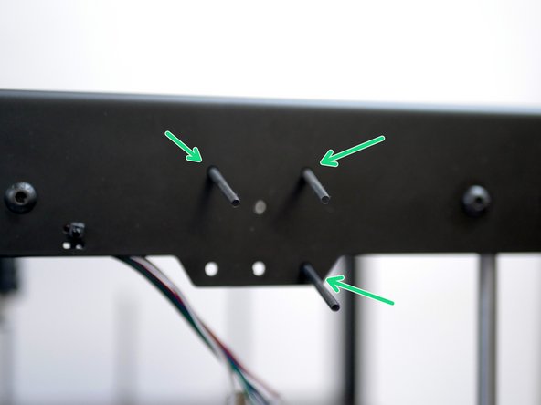
Feed them into holes on the top panel, from the inside.
-
Secure the extruder onto the top panel.
-
Fix the cables into the motor and filament sensor as shown.
-
Repeat the same on the other side of the top panel also.
-
-
-
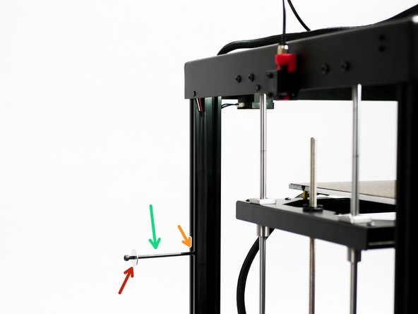
Fix the spool holder assembly to the side of the printer:
-
M5 x 100mm Bolt
-
M5 Penny Washer
-
M5 T-Nut
-
With the Dual Switching Hotend setup this needs to be done on both sides of the printer.
-
-
-
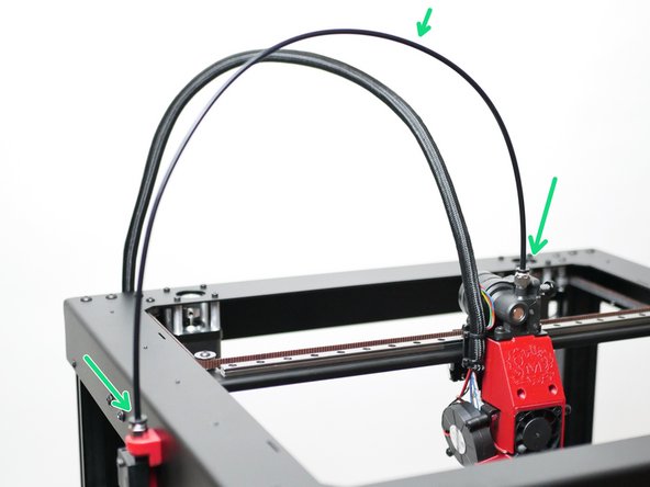
DSH: Fix the PTFE tubing from the hotend to the extruders. The left side of the hotend goes to the left extruder and vice versa.
-
Direct Drive: Fix the PTFE tubing from the orbiter extruder to the feeder on the left side of the printer.
-
-
-
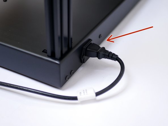
Plug the power cable into the back of the printer.
-
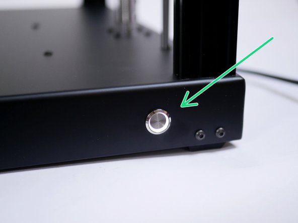
Power on with the switch on the front of the base.
-
If you find your power switch getting stuck 'ON', it is likely secured on too tightly. Loosen the nut holding it to the base.
-
-
-
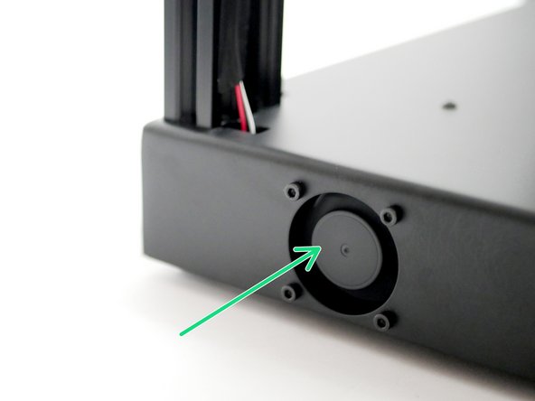
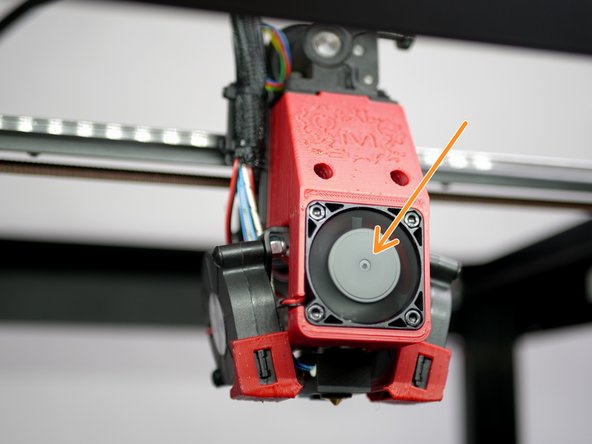
Powering on for the first time should result in the following:
-
Electronics Fan should spin.
-
Hotend Cooling Fan/s should spin
-
LED's should light up.
-
-
-
Everything should already be set-up, but to be safe we recommend running through all of the pre-flight steps here:
-
-
-
-
-
Follow the steps here for your first print:
-
-
-
-
-
Follow the guide here for installing the Enclosure. Some steps have already been done for you.
-