
-
-
Before installing this upgrade you will need a Raspberry Pi board. If you don't already own one from a previous project you can purchase one relatively easily locally.
-
We also sell the Raspberry Pi B+ (recommended) here on our webstore.
-
You can alternatively also use the Raspberry Pi Zero W for this upgrade but it's strongly recommended that you use the Pi 3 B+ board.
-
Make sure the Raspberry Pi board you use has an on board WiFi receiver, else you will need to use an ethernet cable (included) or USB receiver.
-
-
-
Fix the four Raspberry Pi standoffs to the Base with four M2.5 x 6mm bolts.
-
M2.5 x 10mm standoff
-
M2.5 x 6mm bolt
-
If you plan on using the Raspberry Pi Zero W then mount the standoffs in these positions.
-
Use the pliers to place and hold the bolt in place whilst tightening the standoff from underneath where the platform beam makes it difficult to get to.
-
-
-
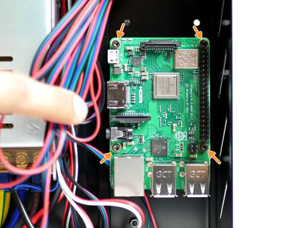
Mount your Raspberry Pi to the base with four M2.5 x 6mm bolts.
-
-
-
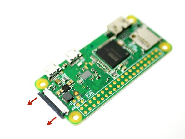
Before mounting the raspberry Pi Zero W, connect to it the golden ribbon cable for the camera.
-
Pull back the black bar on the connector.
-
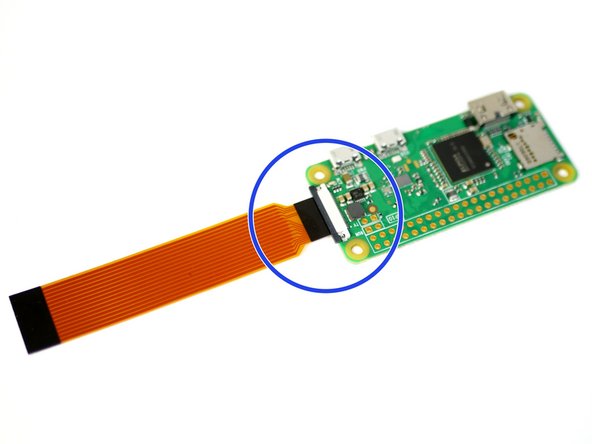
Connect the golden ribbon cable to the Raspberry Pi with the black side up. Push the black bar back in to lock the cable into the connector.
-
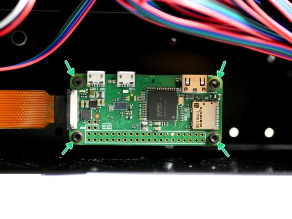
Mount using four M2.5 x 6mm bolts.
-
-
-
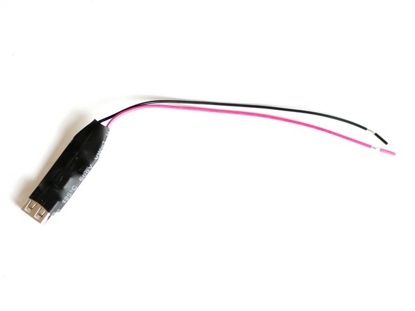
Connect the USB convertor to the power supply.
-
Connect the red cable to a positive terminal and the black cable to a negative terminal.
-
-
-
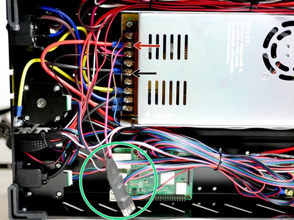
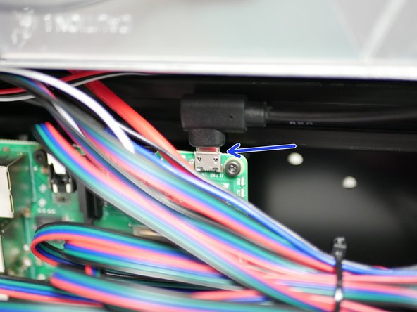
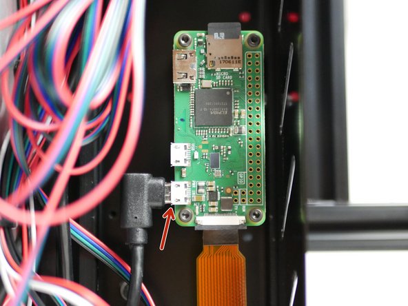
Connect the USB power cable to the Raspberry Pi.
-
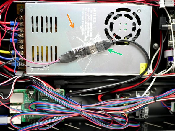
Connect the other side of the cable to the power supply USB connector.
-
Tape the connector to the back of the power supply.
-
Avoid covering any of the vents with tape!
-
If you're using the Pi Zero W, make sure to connect the power cable to the connector nearest the ribbon cable like shown in the third image.
-
-
-
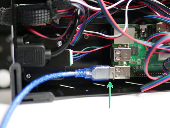
Connect the printers USB cable to the Raspberry Pi.
-
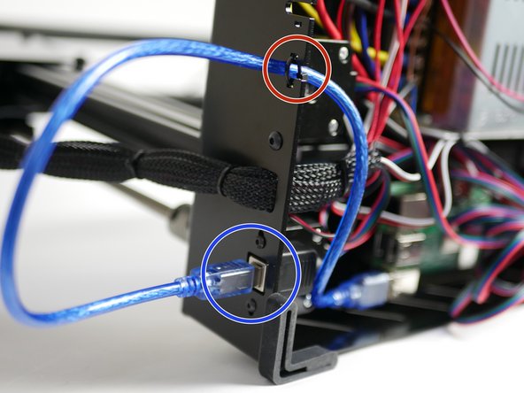
Connect the other end of the cable to the port on the back of the printer.
-
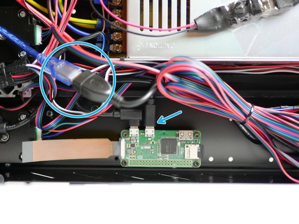
Cable tie the cable to the base like shown.
-
Use the OTG cable adapter to connect to the Pi Zero W.
-
-
-
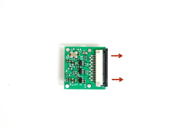
Carefully pull back the black bar on the connector on the back of the Pi camera.
-
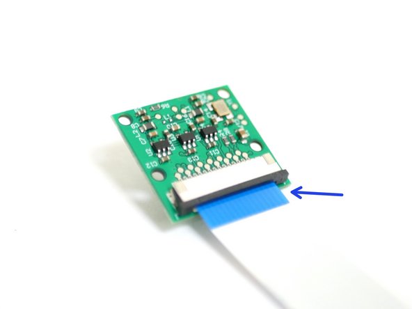
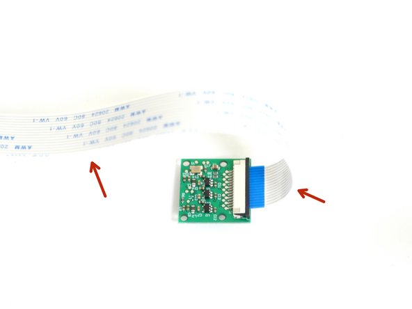
Connect the 60cm ribbon cable to the Pi Cam with the blue tab facing towards you.
-
-
-
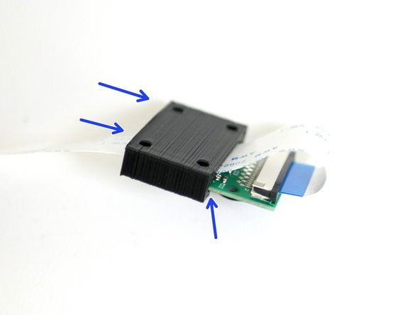
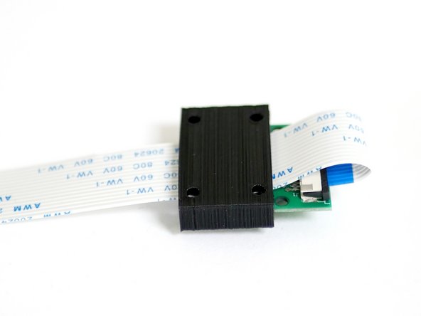
With the camera placed face down fold the ribbon cable over to the left.
-
Slide the 3D Printed cover onto the Pi Cam with the ribbon cable looped over and sandwiched between them.
-
-
-
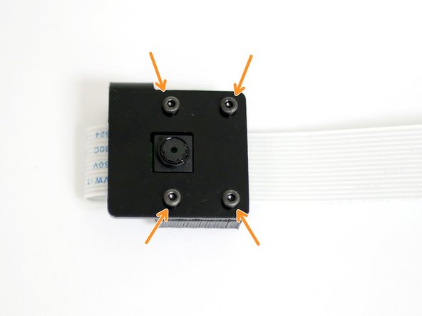
Fix the Pi Camera to the metal casing with:
-
M2 x 10mm bolt
-
M2 Nut
-
Take care to match the orientation in the photos.
-
-
-
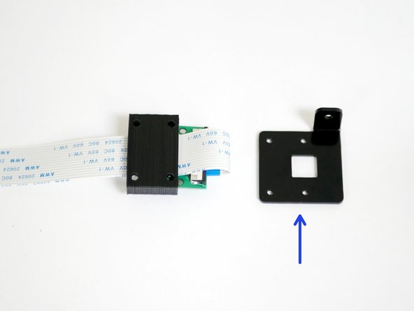
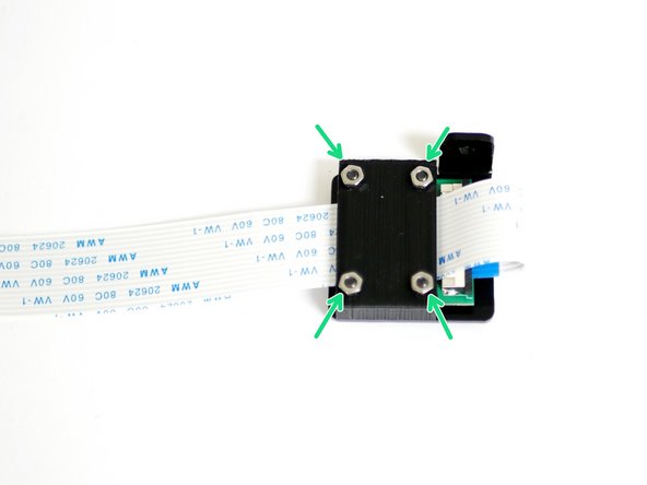
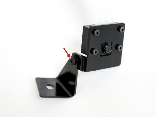
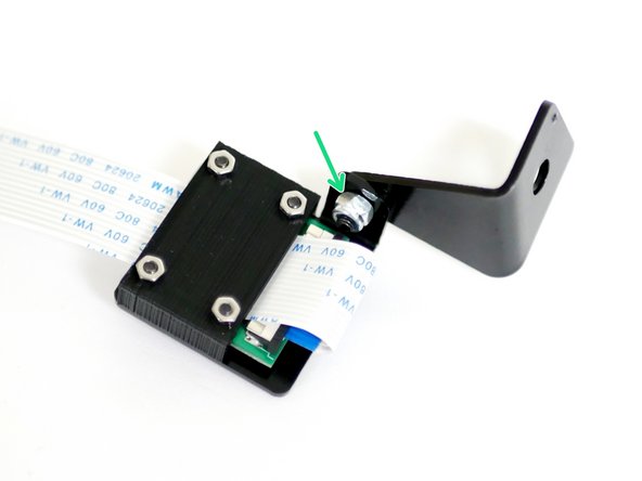
Fix the Pi Cam case assembly to the metal mounting bracket.
-
M3 x 8mm bolt
-
M3 Nyloc Nut
-
Orientate as shown in the photos.
-
-
-
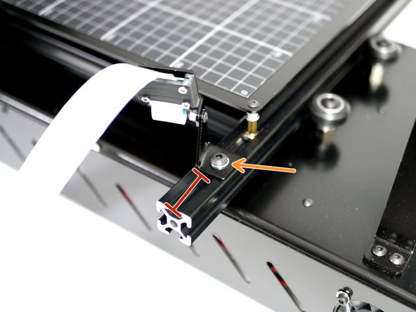
Mount the Pi Cam to the lower left extrusion of the platform with an M5 x 8mm bolt, M5 washer and M5 T-Nut.
-
Mount approximately 1 inch in from the end of the beam.
-
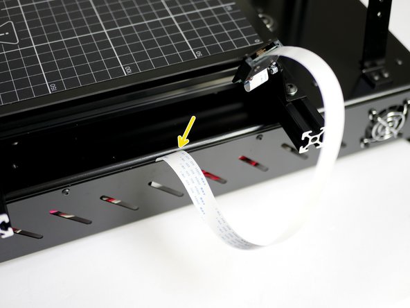
Feed the cable between the side panel and base.
-
-
-
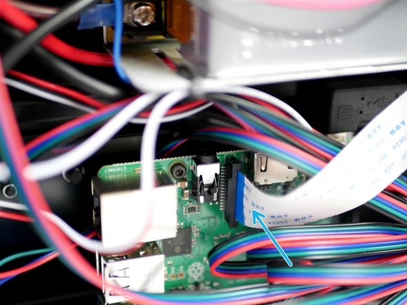
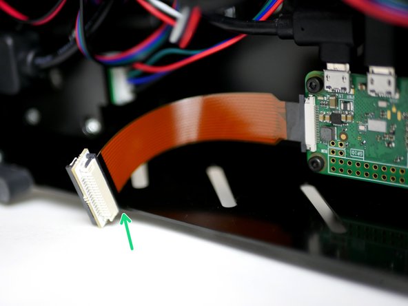
Connect the other end of the cable to the Raspberry Pi.
-
Make sure the blue side of the cable is facing the USB ports.
-
-
-
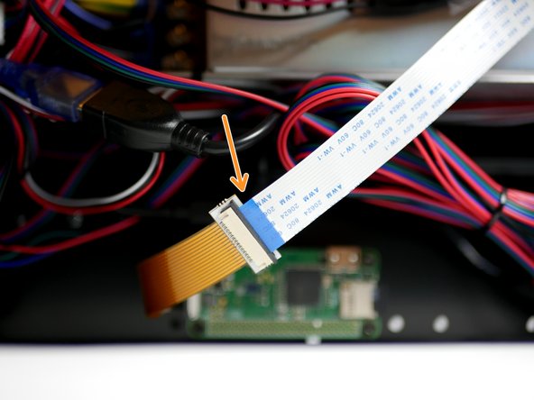
Connect the Pi cam Cable extender to the short golden cable from the Pi Zero W like shown, with the black side facing up.
-
Connect to the other side of the extender to the Pi cam cable from the Pi Cam like shown with the blue side facing up.
-


Cancel: I did not complete this guide.
8 other people completed this guide.
