Parts
No parts specified.
-
-
Fix one of the NEMA 17 motors to the base like shown.
-
Nema 17 motor
-
M3 x 6mm
-
The cable connector should to be facing upwards.
-
-
-
Align the Z-Pillar to the base like shown in the first image.
-
Align a Motor underneath it also with the connector pointing upwards.
-
Fix everything together with four M3 x 8mm bolts.
-
-
-
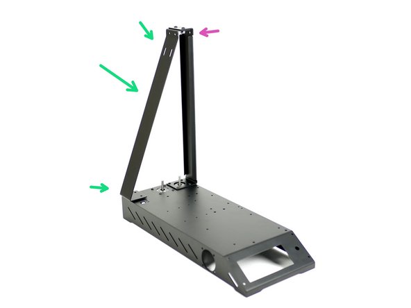
Take the Z-Pillar and align it into position with the base assembly.
-
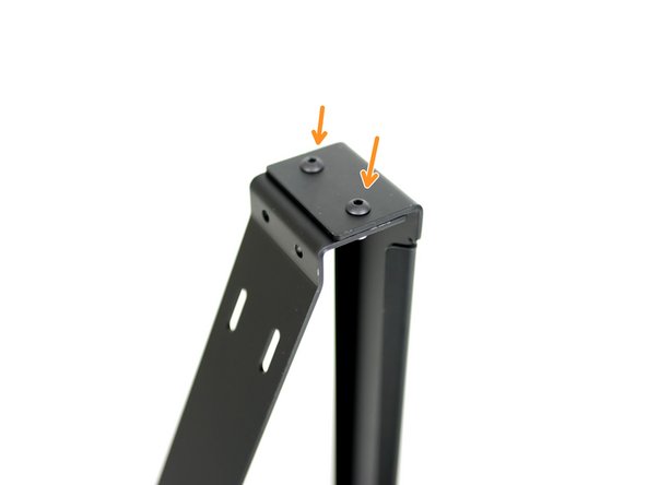
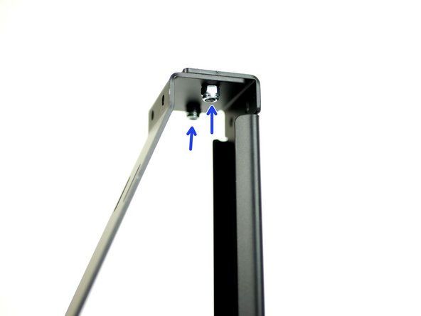
Fix the top of the support pillar to the main pillar with two M4x10mm bolts and M4 nyloc nuts.
-
M4 x 10mm bolt
-
M4 Nyloc Nut
-
-
-
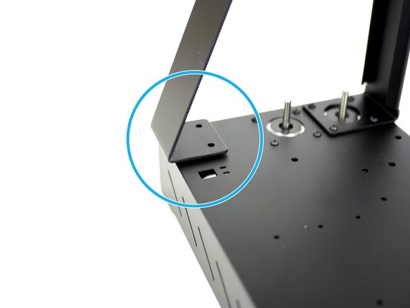
Fix the support pillar to the base.
-
M4 x 10mm bolt
-
M4 nyloc nut
-
-
-
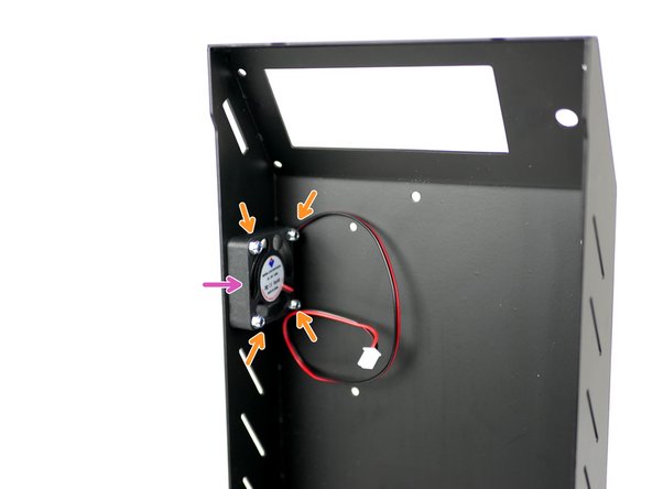
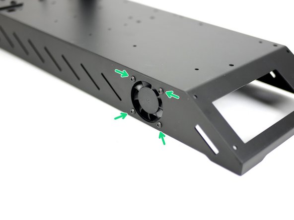
Fix the 40mm electronics fan onto the side of the base.
-
M3 x 16mm bolt
-
M3 nyloc
-
Ensure that the sticker side is facing into the base.
-
-
-
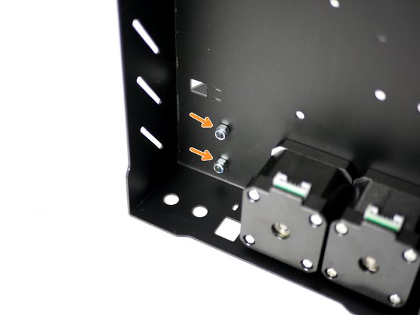
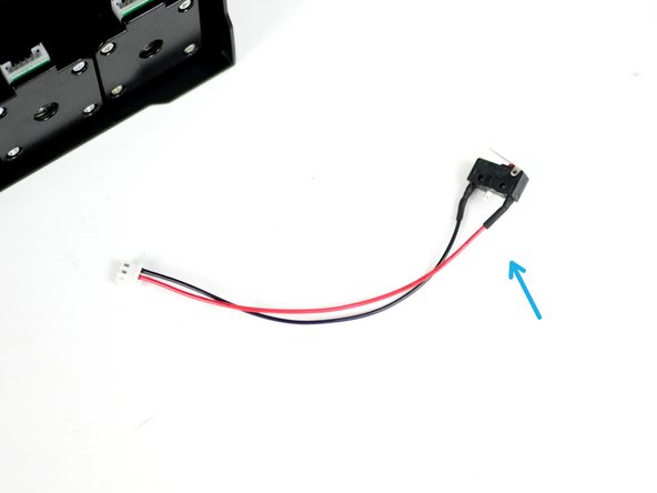
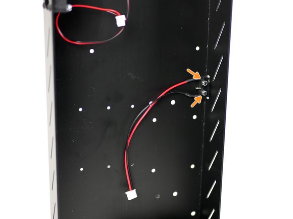
Fix the X-Endstop (it is the one with the shorter cable) to the inside of the base.
-
M2.5mm bolt
-
M2.5 nyloc nut
-
Make sure that the switch's lever is pointing towards the back of the base.
-
-
-
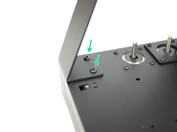
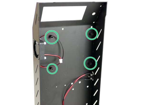
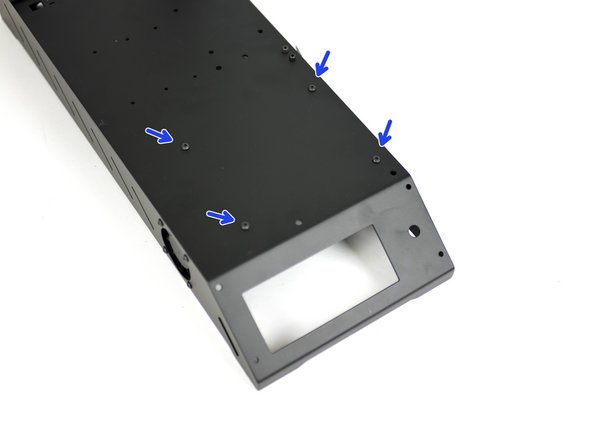
Fix the control board mounts onto the inside of the base like shown.
-
M3 x 10mm stand-off
-
M3 x 6mm bolt
-
-
-
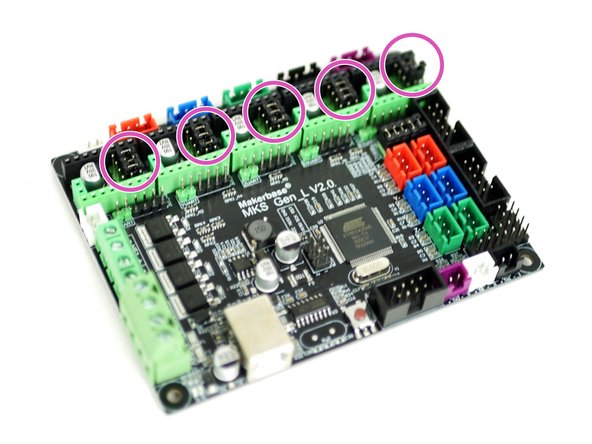
If you have the TMC2208 upgrade you do not need to install these jumpers. See here for details.
-
Take the MKS Gen_L v2 control board out of its packaging. Avoid doing this on carpet or when wearing socks on carpet as static could damage the board.
-
Touching a large metal object will ground you.
-
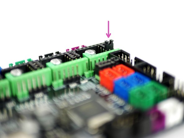
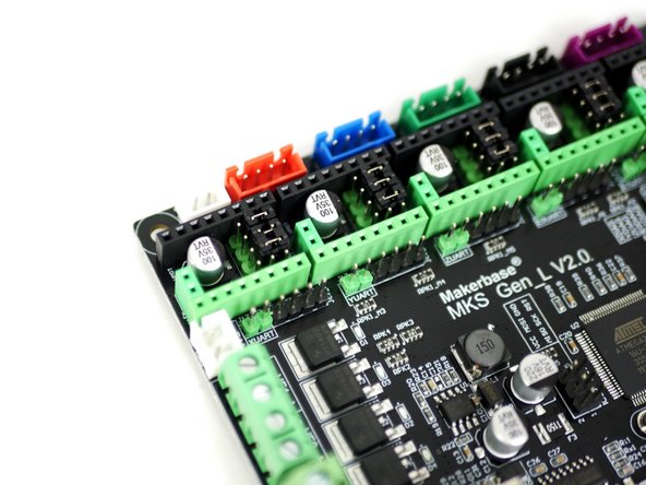
Install the jumpers as shown on all of the motor positions on the board.
-
-
-
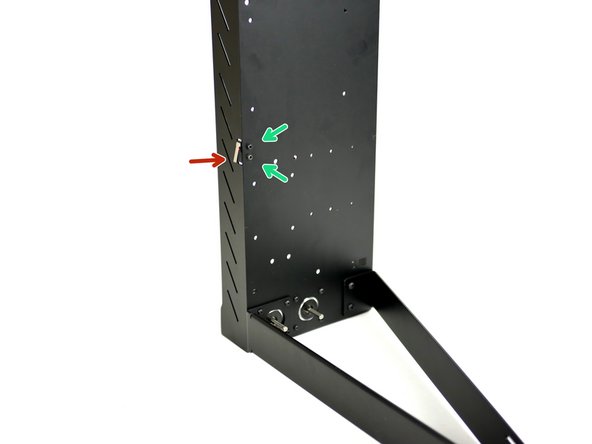
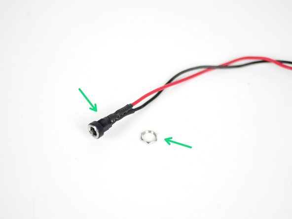
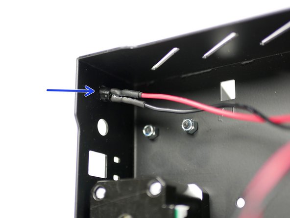
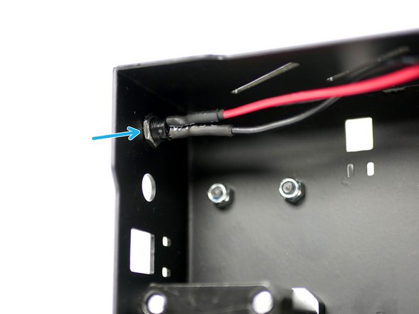
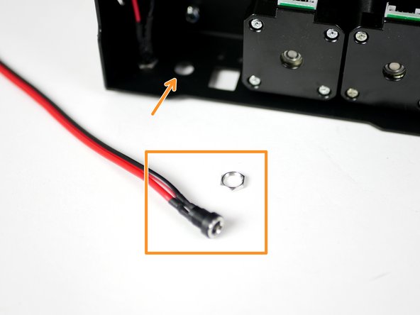
Take the power port mount and remove the nut.
-
Thread it into the back of the base through the hole nearest the base side.
-
Fix it in place by re-threading on the nut.
-
-
-
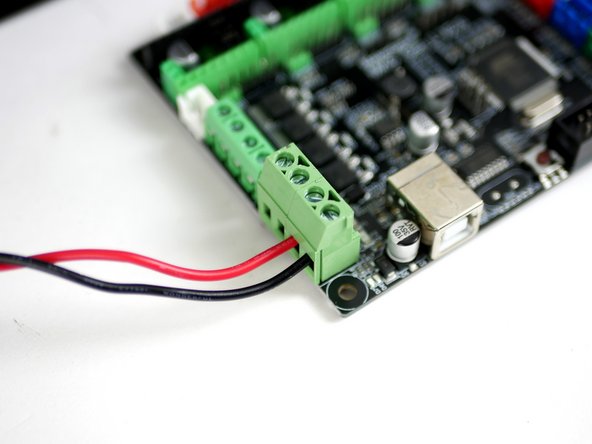
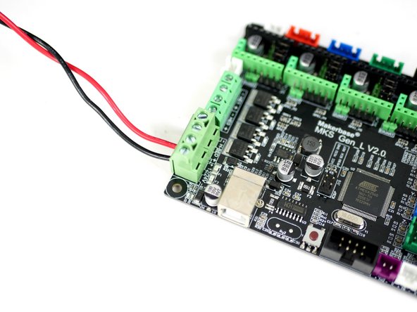
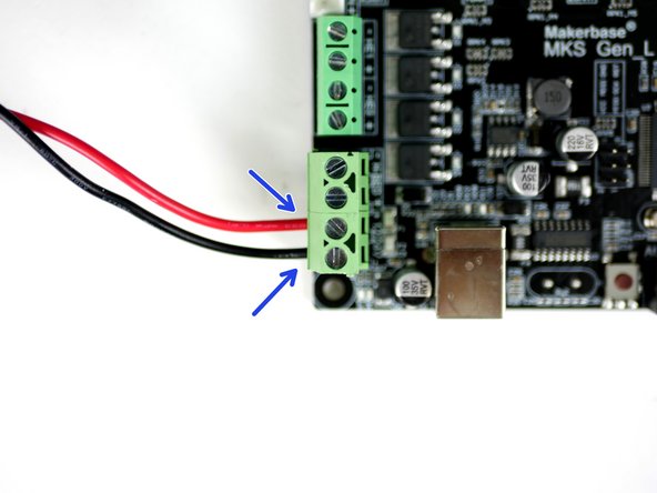
Using a small flat head screw driver fix the power cables into the control board like shown.
-
Red cable to positive and black to negative.
-
-
-
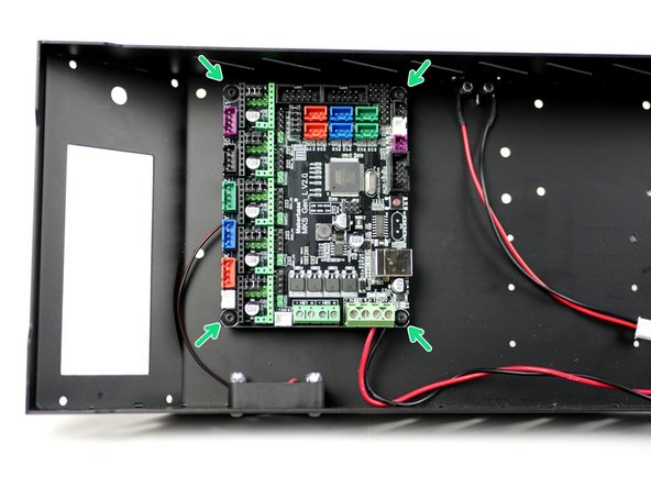
Fix the control board onto the mounts. Make sure to match the orientation shown in the image.
-
M3 x 6mm bolt
-
Don't over tighten these bolts, over tightening can cause the board to warp and become damaged.
-
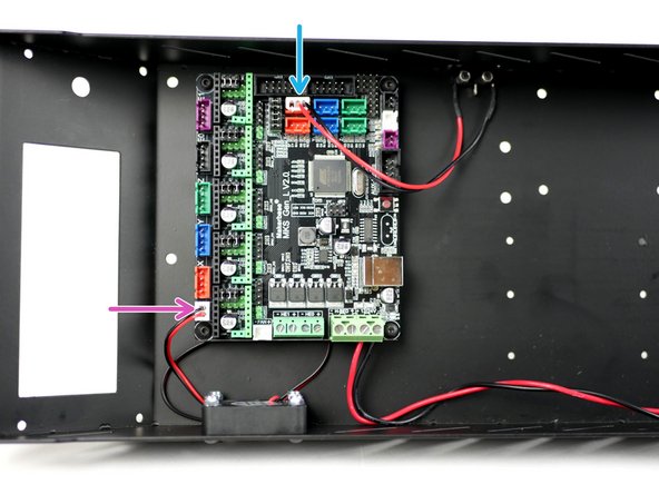
Connect the fan to the control board.
-
Connect the X-Endstop to the control board.
-
-
-
Complete this step even if you do not have the LCD screen upgrade.
-
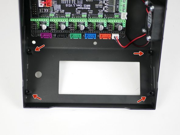
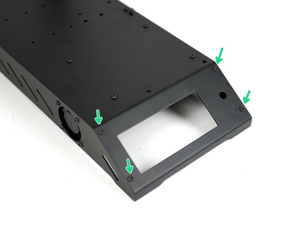
Fix the LCD screen mounts onto the base.
-
M3 x 10mm stand off
-
M3 x 6mm bolt
-
-
-
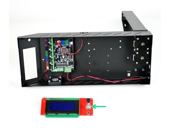
Take the LCD screen out of its packaging. Like with the control board, avoid doing this on carpet or when wearing socks on carpet as static could damage the board.
-
Touching a large metal object before handling will ground you.
-
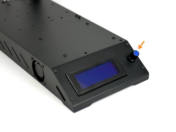
Start by removing the control knob from the screen. The control knob can simply be pulled off, it's not fastened down in any way.
-
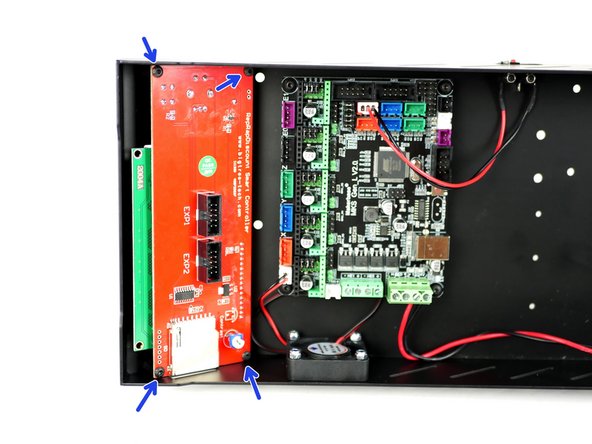
Mount the screen like shown.
-
M3 x 6mm bolt
-
Push the control knob back on.
-
-
-
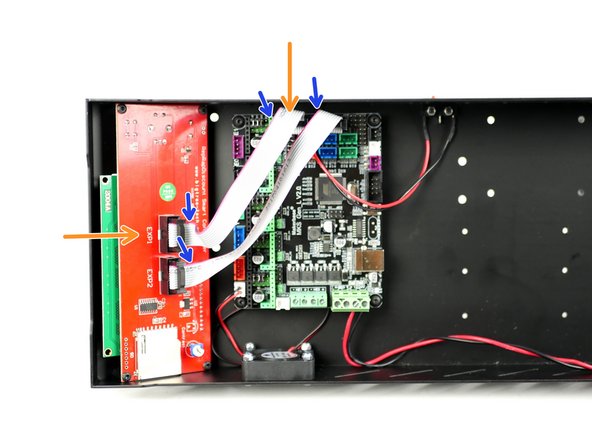
Connect the cables from the LCD screen to the control board like shown.
-
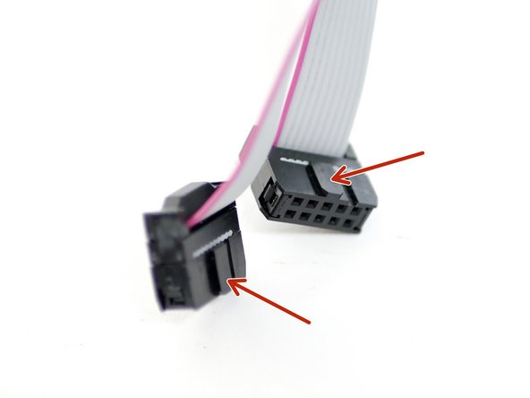
Make sure that your cables match the orientation shown. EXT1 from the LCD screen should go to EXP1 on the board.
-
The red cable should also be on the same side for both cables, like shown.
-
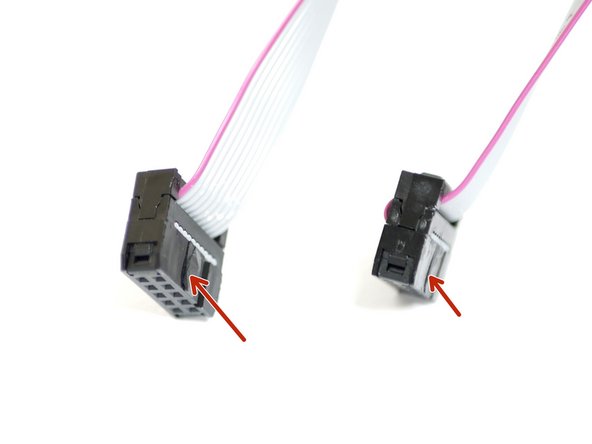
A batch of cables have the connectors reversed, if you find this to be the case you will need to use a craft knife to cut of the direction tab on one side of the connector in order to fit it in the correct way round on the board. Make sure the knife you use to do this is sharp, and cut down, away from the cable itself.
-
-
-
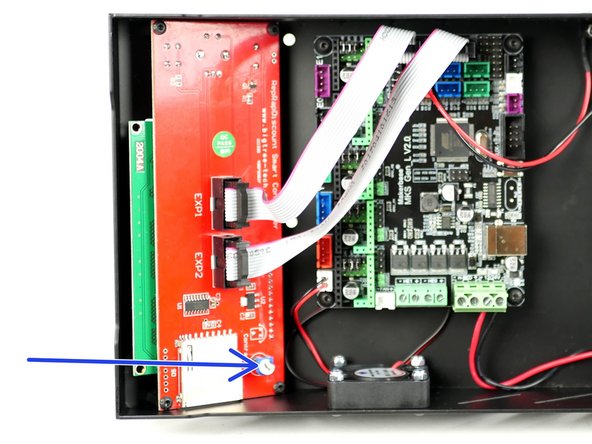
This is a quick note to let you know how to adjust the LCD screen contrast.
-
When you have completed the build and power up for the first time your display might be too faint or be white blocks.
-
You can adjust the contrast with this trim-pot in order to make the display readable.
-
-
-
Only complete this step if you have the heated bed upgrade.
-
The standoffs and bolts for this step can be found in the heated bed fastener pack.
-
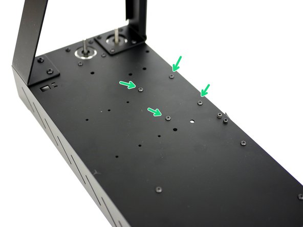
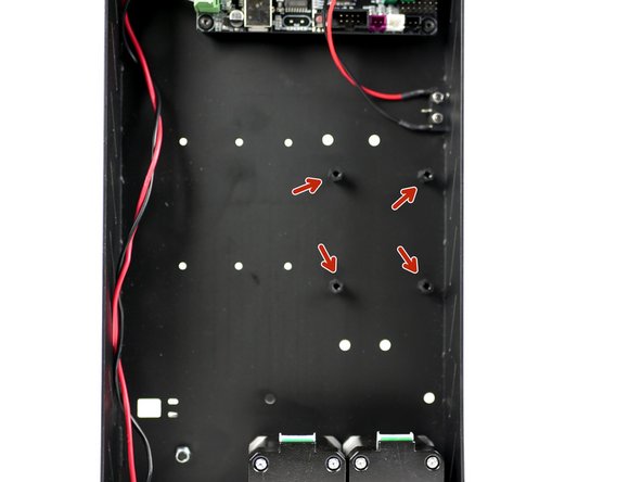
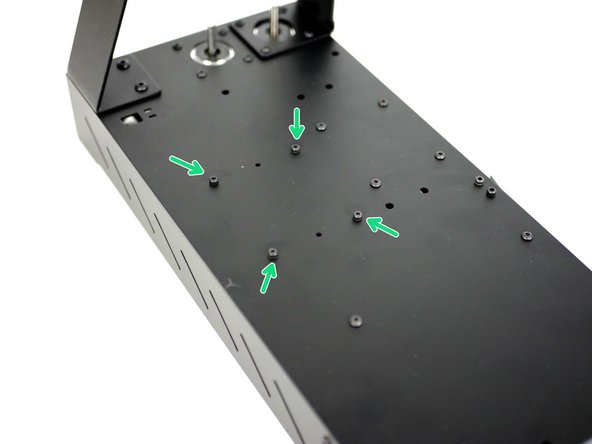
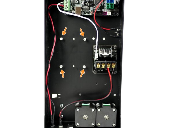
Like the control board, fix the MOSFET stand-offs onto the base in the position shown.
-
M3 x 6mm bolt
-
M3 x 10mm standoff
-
-
-
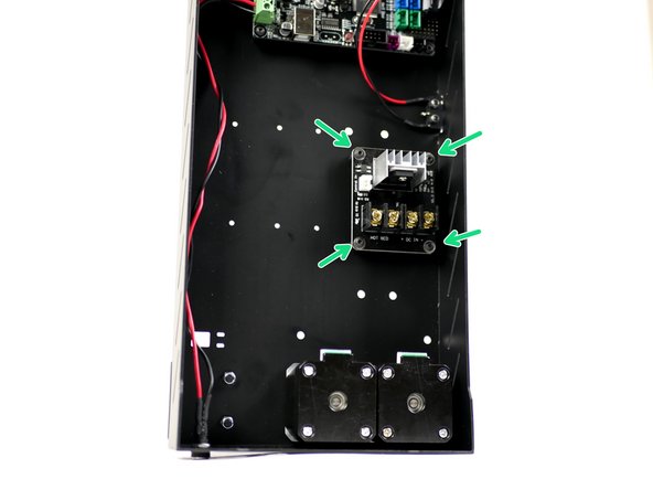
Mount the MOSFET onto the base. Make sure that the power terminals are facing towards the motors.
-
Four M3 x 6mm bolts
-
-
-
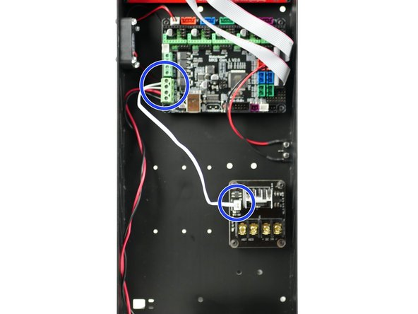
Connect the short white signal cable from the MOSFET to the control board.
-
The polarity into the control board doesn't matter.
-
You may find it easier to install by unmounting the control board first, installing the cable and then plugging it into the MOSFET.
-
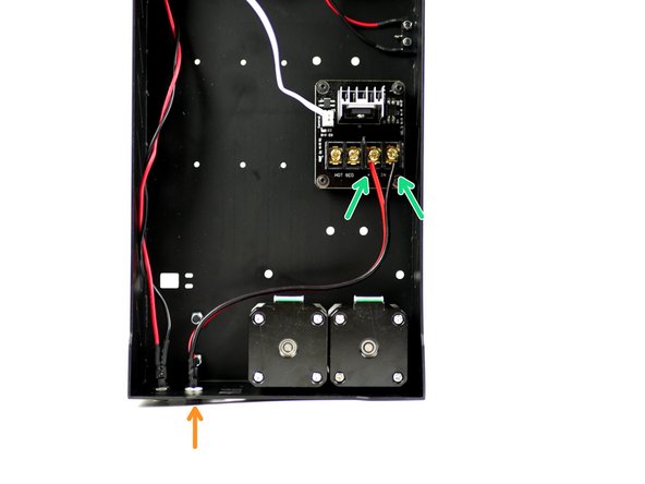
Fix the power mount for the heated bed in the same way as before.
-
Connect the power mounts cables to the MOSFET like shown. Red to positive and black to negative.
-
-
-
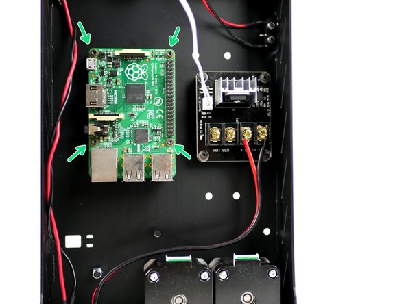
Mount your Raspberry Pi board in the position shown.
-
Fasteners can be found in the OctoPi upgrade.
-
M2.5 x 6mm bolt
-
M2.5 x 10mm stand-off
-