
Parts
No parts specified.
-
-
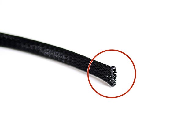
Cut 70CM of the braided cable sleeving.
-
Use a lighter to melt the ends to prevent fraying.
-
-
-
Take two 1m motor cables.
-
Thread the sleaving over both of them.
-
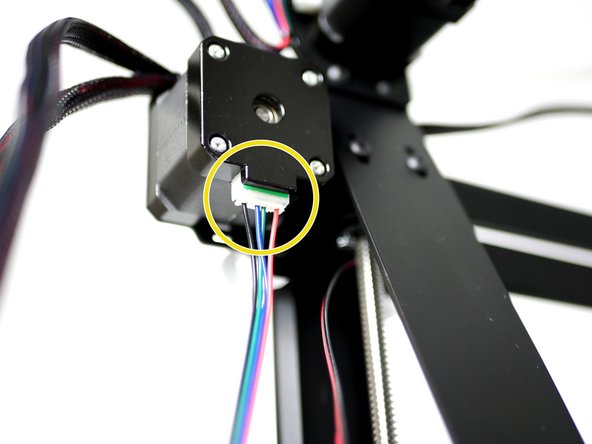
Plug one of the cables into the extruder motor.
-
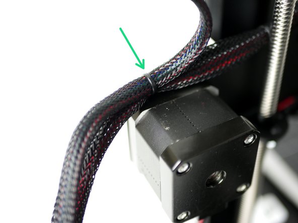
Cable tie that cable to the spool holder bracket.
-
Note, the second cable is there for the dual extrusion upgrade, it is installed now even if you don't have that upgrade.
-
-
-
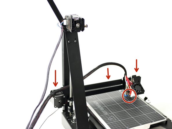
Turn the lead screw to bring the gantry all of the way down, the hotend should be touching the print surface.
-
Cable tie both bunches of cables together to the gantry.
-
-
-
Cut 45CM of the braided cable sleeving.
-
Use a lighter to melt the ends to prevent fraying.
-
-
-
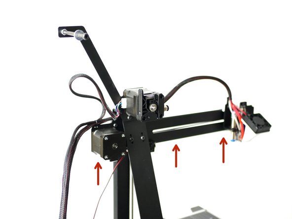
Raise the gantry to the very top.
-
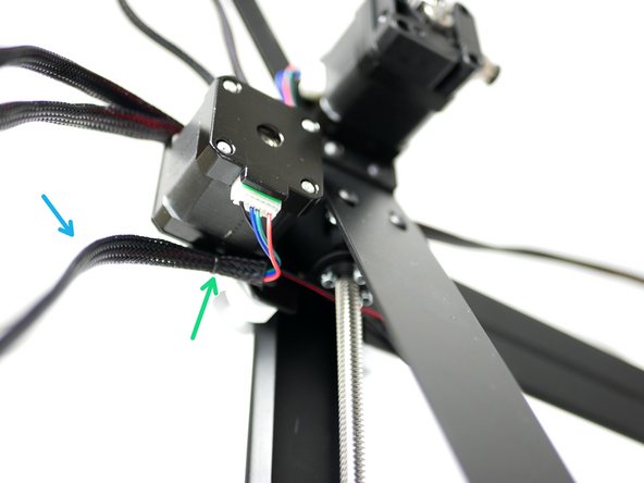
Plug a 1M motor cable into the y-motor.
-
Slide the 45CM cable sleeving over the motor cable and Y-endstop.
-
Cable tie to the bottom of the gantry.
-
-
-
Before tying off the cables together, it may be worth using tape to mark what each of the cables is connected to.
-
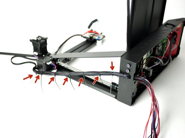
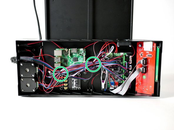
Place the Axis on its side like shown. Use multiple cable ties to create a single branch of cable.
-
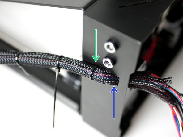
Push all of the cables through the square hole in the back of the base.
-
Use a cable tie to attach the cable branch to the base.
-
-
-
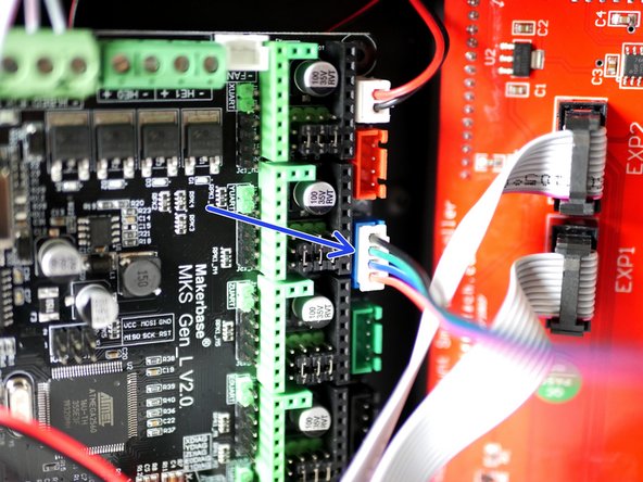
Plug the Y-axis (gantry) motor into the control board.
-
Plug the Y-endstop into the control board.
-
-
-
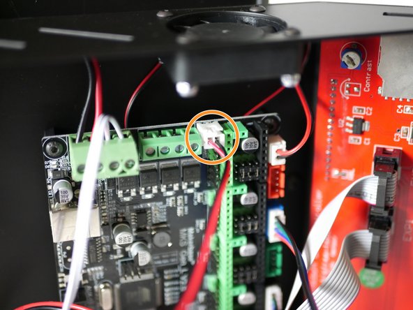
Plug the hotend thermistor into the control board.
-
Secure the hotend heater cables to the terminals on the control board.
-
Their polarity does not matter.
-
-
-
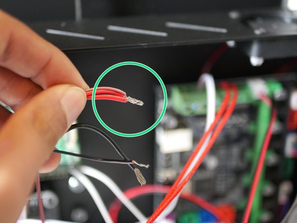
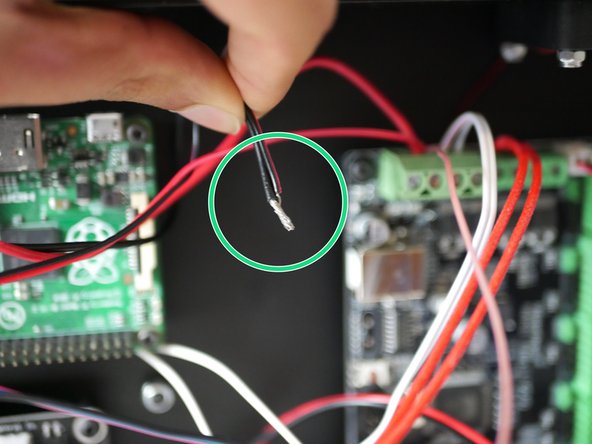
First prepare the 30mm hotend fan (the smaller fan that connects directly onto the hotend) by cutting of the connector and exposing some of the wire.
-
Unplug the power cables from the control board.
-
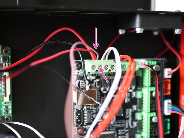
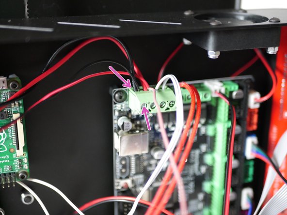
Take the red power cable, the red 30mm hotend fan cable and the brown cable from the probe and wind together.
-
Plug all three back into the control board and secure the terminal tightly.
-
-
-
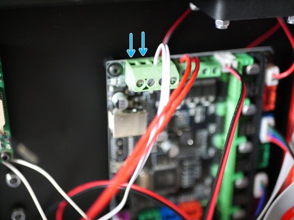
Take the remaining black power cable and black cable form the hotend fan and wind together.
-
Plug both back into the control board and secure the terminal tightly.
-
-
-
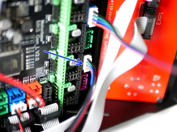
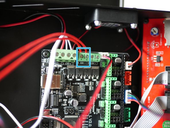
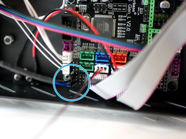
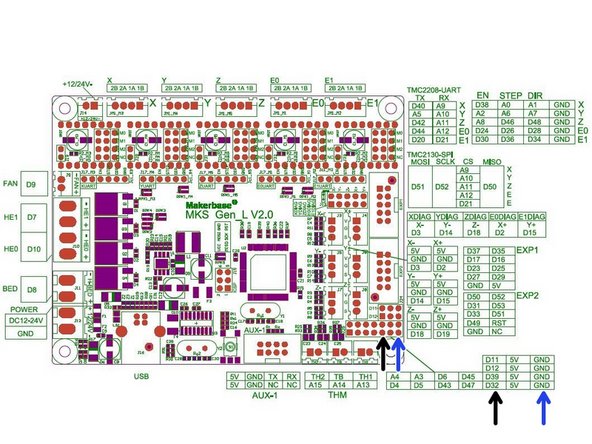
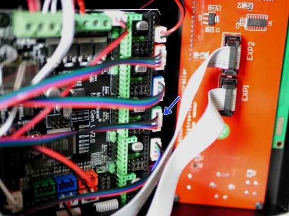
Plug the black and blue probe cables into the positions shown on the control board.
-
Black to D32
-
Blue to GND
-
NOTE: There is an empty pin between the black and blue cables!
-
-
-
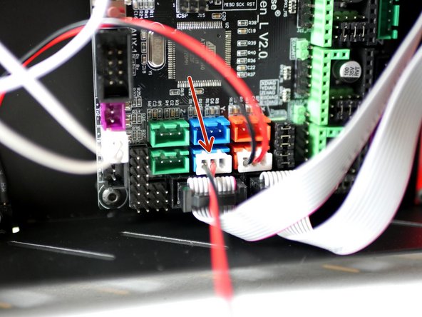
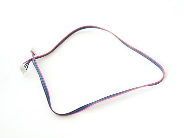
Take one of the 50CM motor cables.
-
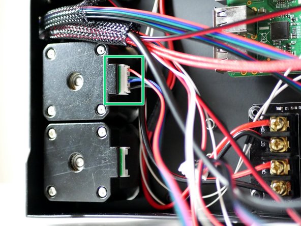
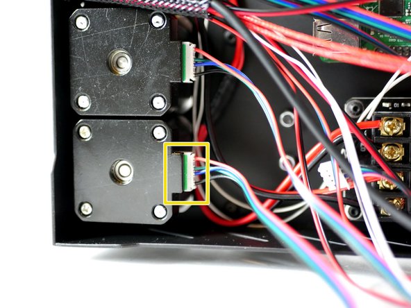
Plug one end into the X-motor.
-
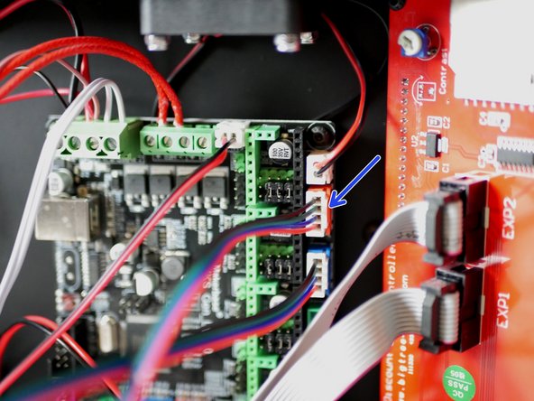
Plug the other end into the control board.
-
-
-
Take the remianing 50CM motor cable.
-
Plug one end into the Z-motor.
-
Plug the other end into the control board.
-
-
-
Skip this step if you do not have the TMC2208 driver upgrade.
-
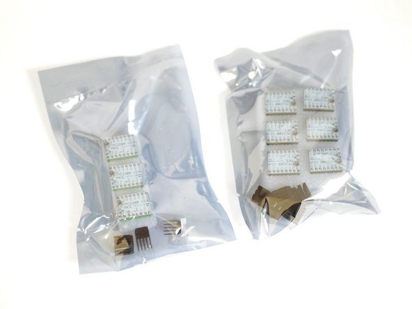
The stepper drivers are the most delicate part of the Axis 3d printer and it is why we've also included a spare. Before opening, make sure that you are grounded (touch a large metal object) to avoid any chance of static damage.
-
The TMC2208 upgrade comes with either 3 or 6 drivers. If you have three you can use two on the x/y axes and keep one as spare, if you have 6 you can use them on the X/Y/Z/E0 (and E1 for dual extrusion) and have one spare.
-
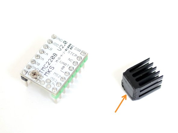
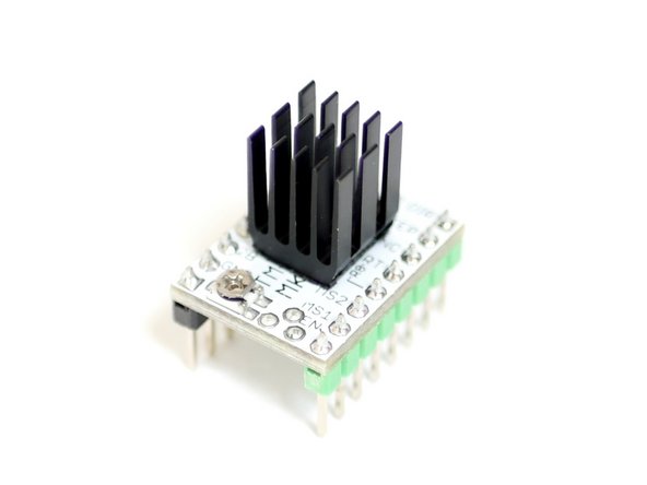
Prepare the TMC2208 stepper drivers by removing them from their packaging and sticking the heat-sink to the top.
-
Make sure that the heat-sink is not touching any of the pins. Orient the fins of the heat-sink as shown.
-
-
-
Skip this step if you do not have the TMC2208 driver upgrade.
-
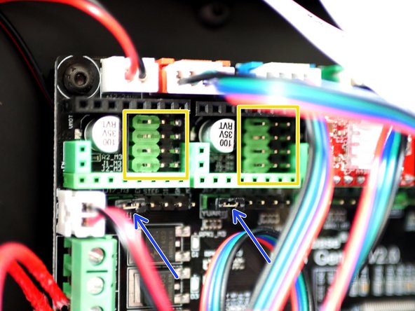
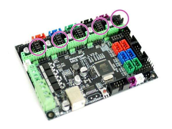
To install the TMC2208 drivers you will need to make sure that there are no jumpers plugged in at the stepper driver locations on the control board.
-
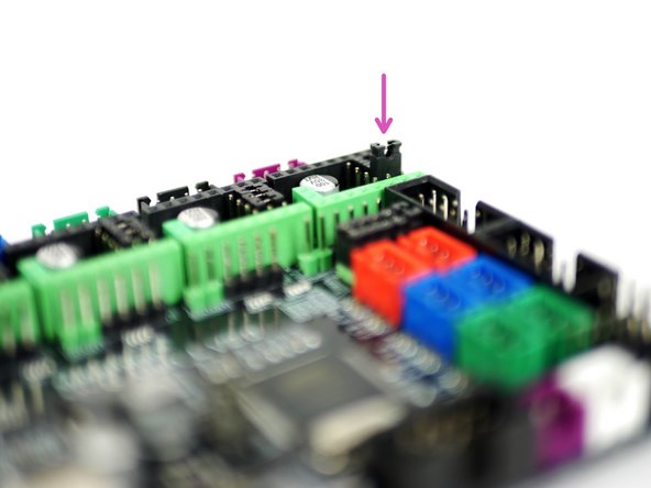
You will however need to make sure that there is one jumper placed on the UART pins for each axis you have a TMC2208 installed.
-
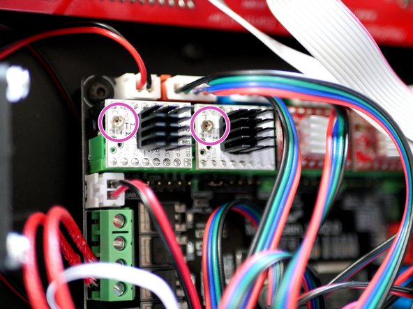
Plug the TMC2208 driver into the positions shown, make sure that the trim-pot is pointing towards the power terminals, installing the driver the wrong way round will destroy it.
-
Note, the trim-pot doesn't need adjusting as these drivers allow us to control the current via the firmware.
-
-
-
The stepper drivers are the most delicate part of the Axis 3d printer and it is why we've also included a spare. Before opening, make sure that you are grounded (touch a large metal object) to avoid any chance of static damage.
-
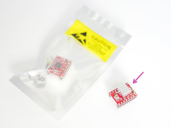
Prepare the A4988 stepper drivers by removing them from their packaging and sticking the heat-sink to the black chip.
-
Make sure that the heat-sink is not touching any of the pins. Orient the fins of the heat-sink as shown.
-
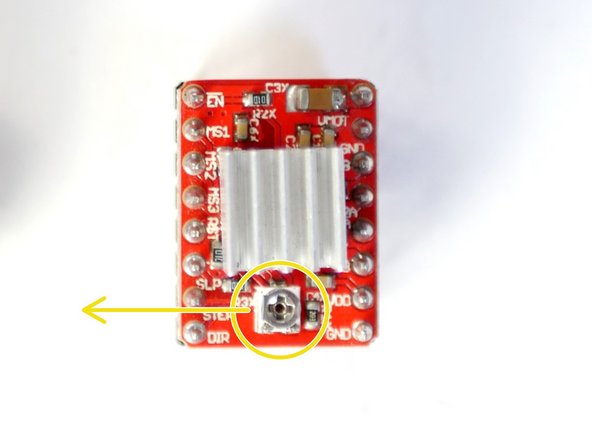
Trimpot: Adjust the trimpot so that flat side is pointing left as shown in the second photo.
-
-
-
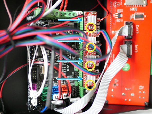
If you do not have any of the TMC2208 drivers you will need to install the A4988 drivers like shown.
-
Under the A4988 driver positions on the control board there needs to be three jumpers installed like shown in the second and third photo.
-
Make sure that all of the drivers are orientated with their trim-pots pointing away from power terminals.
-
Plugging them in the wrong way round will destroy them.
-


Cancel: I did not complete this guide.
18 other people completed this guide.
