
-
-
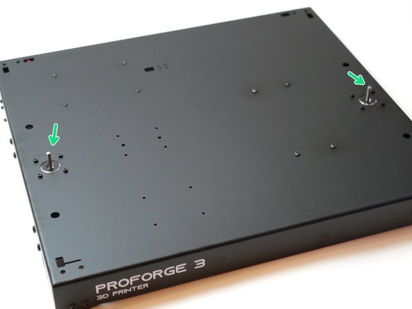
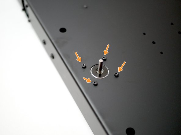
Attach the four rubber feet to the corners of the Base.
-
M4 x 16mm Button
-
M4 Nyloc Nut
-
Photographed are 3D printed feet, however the ones included are injection moulded rubber.
-
The Feet are silicone rubber, pliers will be needed to help hold the nyloc nuts in place whilst fastening. This was an unfortunate oversight, and one we weren't able to correct due to the cost of tooling for these injection moulded parts.
-
-
-
If building the Proforge 3.5, skip this step.
-
Fix the four metal brackets to the sides of the base.
-
Bracket
-
M5 x 3mm Spacer
-
M5 x 16mm Button
-
M5 Nyloc Nut
-
Do not tighten yet, just hand fasten to leave the bracket fixed loosely.
-
Make sure the bolt on the bracket is facing outwards and away from the centre of the base panel.
-
-
-
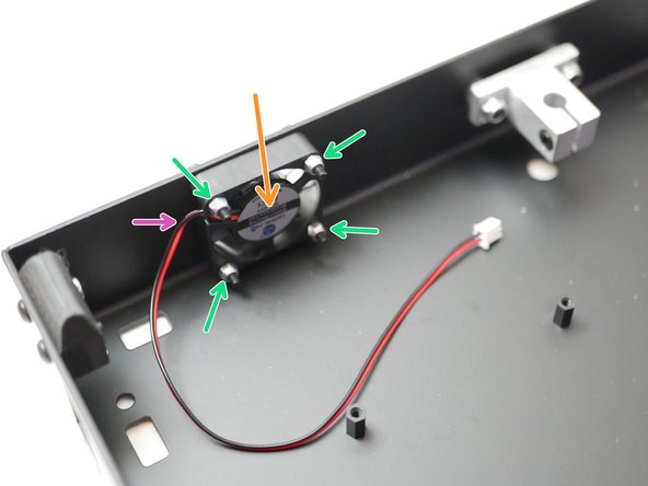
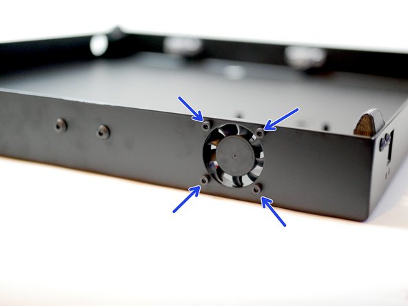
Install the electronics fan as shown:
-
Make sure the sticker side of the fan points inwards.
-
Make sure the cable is also orientated as shown.
-
M3 x 20mm CAP
-
M3 Nyloc
-
-
-
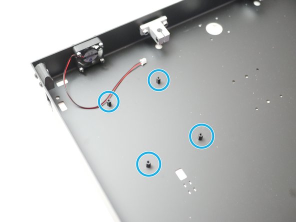
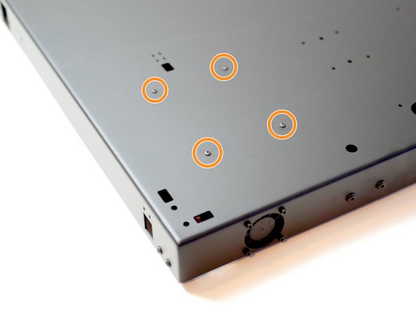
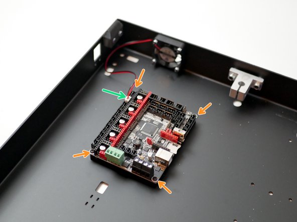
Fix four stand-offs to the base:
-
M3 x 10mm threaded stand-off
-
M3 x 6mm Button
-
Before removing the control board from it's packaging, make sure that you are earthed, you can do this by touching a large metal object. This is to ensure a static shock doesn't damage the board.
-
Fix the board onto the mounts with four M3 x 6mm button head bolts.
-
Make sure the board is orientated as shown.
-
Plug the electronics fan into the control board as shown.
-
-
-
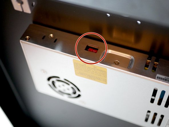
Before mounting the PSU, check that it's voltage input is adjusted correctly for your location. The switch on the side of the unit should be set to your mains voltage. In the UK this would be 230v, in the USA it would be set 110v.
-
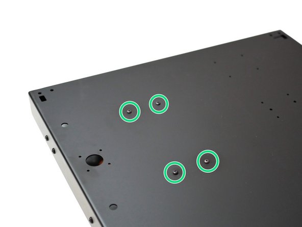
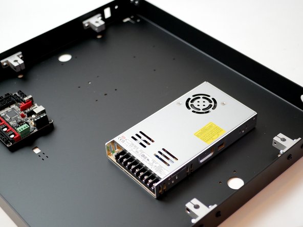
Fix the PSU to the base with four M4 x 6mm button head bolts.
-
An easy way to line up the holes is to place the PSU under the base and look through the holes from the top until they line up, and you can secure one of the bolts. The rest should then easily follow.
-
Note the orientation of the PSU, it should match the third photo.
-
-
-
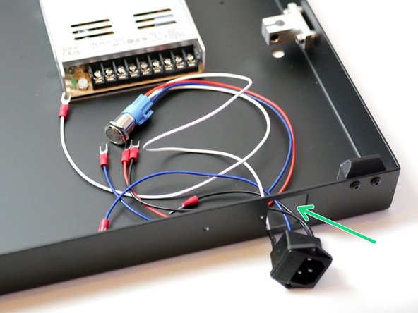
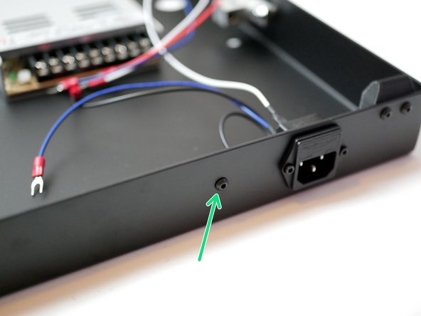
Push the switch side of the assembly in through the rectangular cut-out at the back of the base.
-
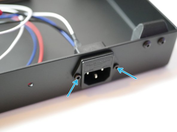
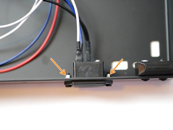
Push the socket in and and secure it in place with:
-
M3 x 10mm Cap
-
M3 Nyloc
-
Again, match the orientation of the socket as shown in the second image.
-
-
-
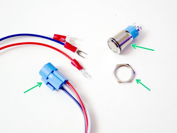
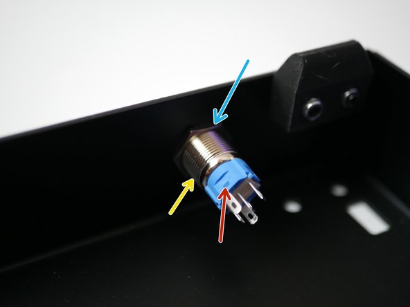
Disassemble the switch assembly by pulling the adaptor off the switch and undoing the nut.
-
Push the switch in though the hole at the front of the base.
-
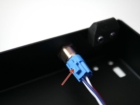
Fix the switch in place by tightening the nut back onto it. DO NOT OVERTIGHTEN.
-
Plug the cable adapter back on, note the orientation, the side with the release lever should go on the side that has the tab on the switch housing.
-
-
-
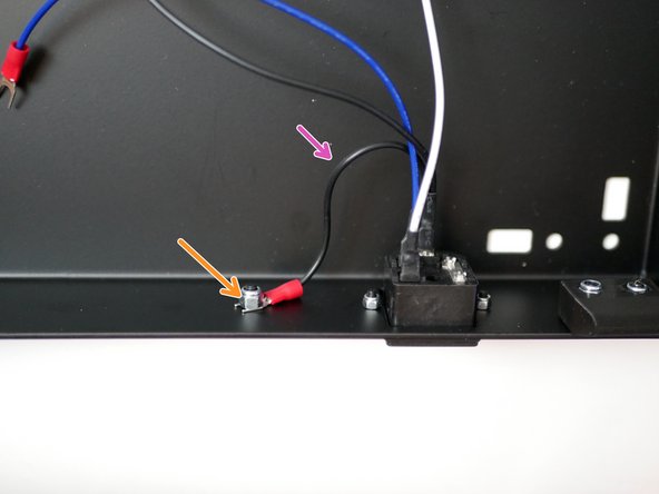
Fix the earth cable (shorter black cable) from the socket to the frame.
-
M4 x 10mm Button
-
M4 Nyloc
-
Scruff up the surface of the Base where the terminal makes contact here to get a better electrical contact with the frame.
-
-
-
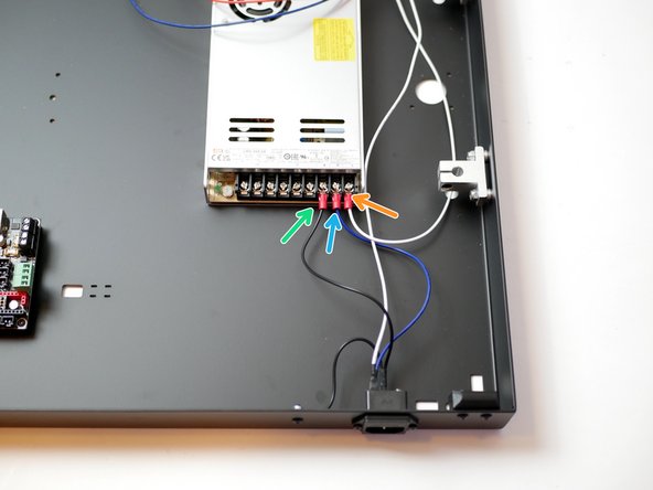
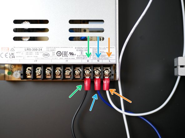
Connect the longer black cable from the socket to the power supplies earth terminal.
-
Connect the blue cable from the socket to the neutral terminal on the power supply.
-
Connect the white cable from the switch to the live terminal on the power supply.
-
-
-
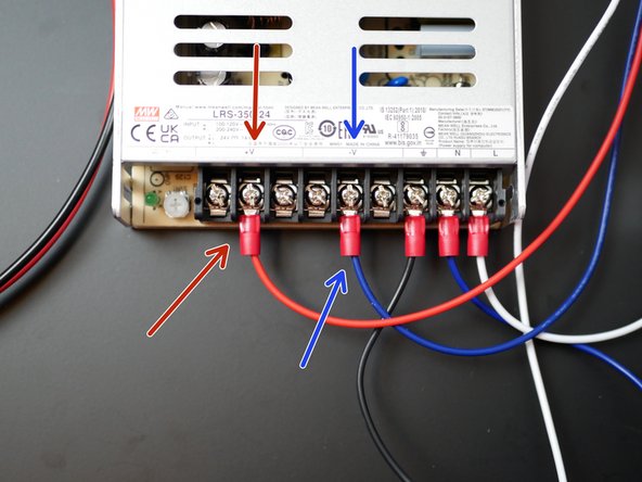
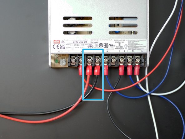
Connect the red and blue cables from the switch to the terminal on the power supply as shown:
-
Red to positive
-
Blue to negative
-
-
-
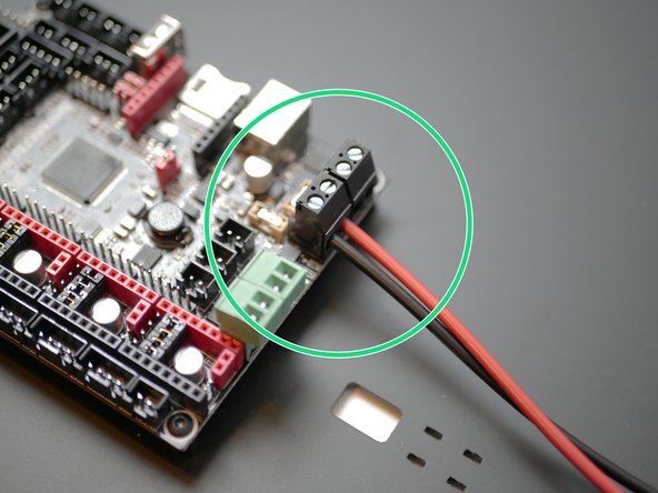
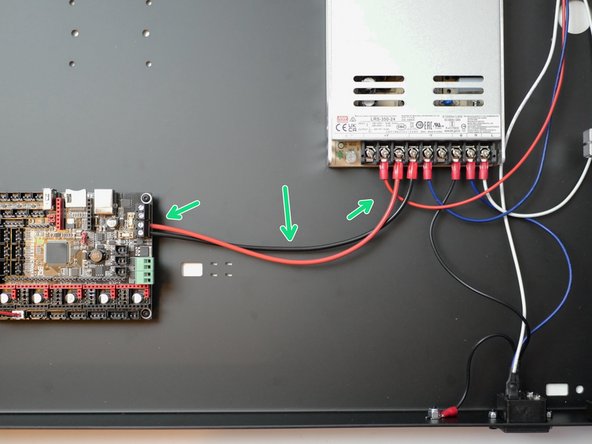
Secure the black and red power cables to the control board as shown.
-
On the power supply side, the red cable goes to positive and the black to negative.
-
Double check that all the cables are connected correctly, as shown in the images. Incorrectly connecting the cables can cause irreversible damage.
-
-
-
If building the Proforge 3.5, skip this step.
-
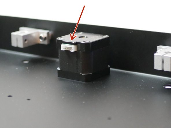
Fix the two 1.8 degree NEMA 17 motors to the base. Serial No. 42BYGH438.
-
M3 x 6mm Cap Head Bolt
-
Make sure that the cable header, on the motor, is facing inwards.
-


Cancel: I did not complete this guide.
9 other people completed this guide.

3 Comments
The rubber feet don’t hold the nuts well enough to tighten the screws. I had to try and shove a socket wrench head in to hold it well enough. Tightening those 8 screws took over half the total build time for this part.
I couldn’t find the threaded standoffs in the BOM/Parts packing list.
Looking through the kits, I found only 2x m3 threaded spacers. The only 4x threaded spacers I can find are M2.5. I used PC motherboard standoffs to replace the parts.
Kenn Walker - Resolved on Release Reply
The 2 motors plastic connectors were Brocken, but had to install them and HOD cable will not be loosen. The cable connectors are very weak and loose in the cartoon guess need better backings
Wadi Ramahi - Resolved on Release Reply
This guide lists “M3 x 10mm threaded stand-off” in Step 4, but the packaging calls that “M3 x 10mm Threaded Spacer”
I don’t see anything in the directions indicating how to tell which motors are 1.8 degree motors. I googled the 2 model numbers on the motors, and didn’t see anything related. I did eventually find on Shengyang Motor’s website that the “42BYGH” series is 1.8 degrees, and “42BYGE” series is 0.9 degrees.
Greg Murnane - Resolved on Release Reply