-
-
Prepare the following extrusions by threading onto the ends two M5 x 10mm button head bolts.
-
4x 420mm Extrusion
-
4x 470mm Extrusion
-
The 470mm extrusions should be the ones without the holes drilled through the sides.
-
Leave a gap of around 3-4mm.
-
-
-
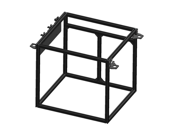
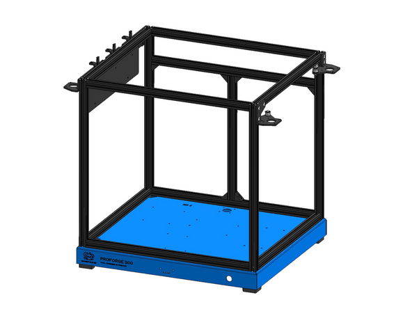
Build the frame as shown in the diagram.
-
470mm Extrusion (prepared from previous step)
-
420mm Extrusion (prepared from previous step)
-
470mm Extrusion (with holes)
-
We're aware that the initial batch of extrusions have some QC issues where the hole is not drilled cleanly, we've raised the issue with our manufacturer. If you have an extrusion where the hole is not cleanly drilled we recommend redrilling with a 5mm bit.
-
Drop the extrusions that you prepared in the previous steps into the grooves of the 470mm extrusions as shown.
-
Use the Allen key to go through the holes on the sides of the 470mm extrusions to tighten the bolts and hold the extrusions together.
-
-
-
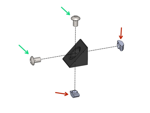
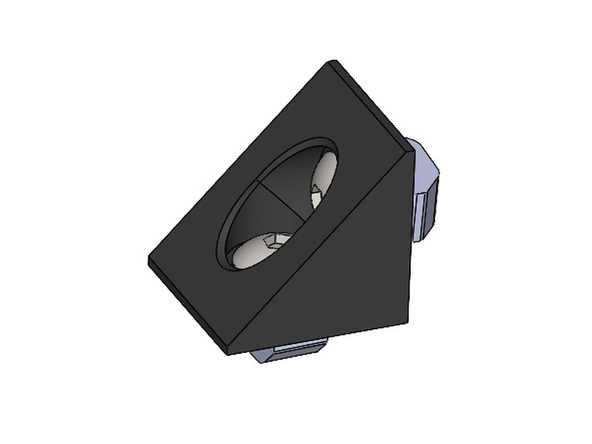
Build 6 corner bracket assemblies with the bolts and T-nut fastened on loosely.
-
M5 x 8mm Button Head Bolt
-
M5 T-Nut
-
-
-
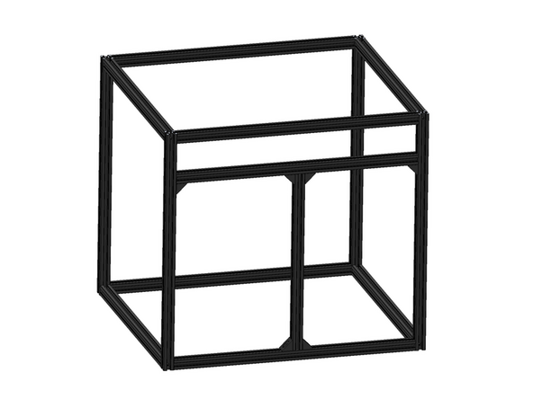
Add to the frame:
-
470mm Extrusion
-
350mm Extrusion
-
Fix the extrusions in place as shown with the corner brackets built in the previous step.
-
-
-
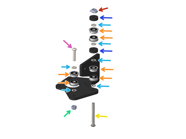
Fix the Idler assemblies onto the Front Motor Bracket as shown.
-
M4 x 20mm Button Head Bolt
-
M4 x 8 x 0.5mm Shim
-
F624ZZ Bearing
-
M4 Nyloc Nut
-
M4 x 40mm Button Head Bolt
-
M4 x 4mm Spacer
-
M4 T-Nut
-
-
-
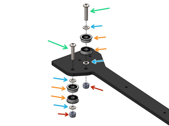
Fix the Idler assemblies onto the Rear Motor Bracket as shown.
-
M4 x 30mm Button Head Bolt
-
M4 x 20mm Button Head Bolt
-
M4 x 8 x 0.5mm Shim
-
F624ZZ Bearing
-
M4 Nyloc Nut
-
-
-
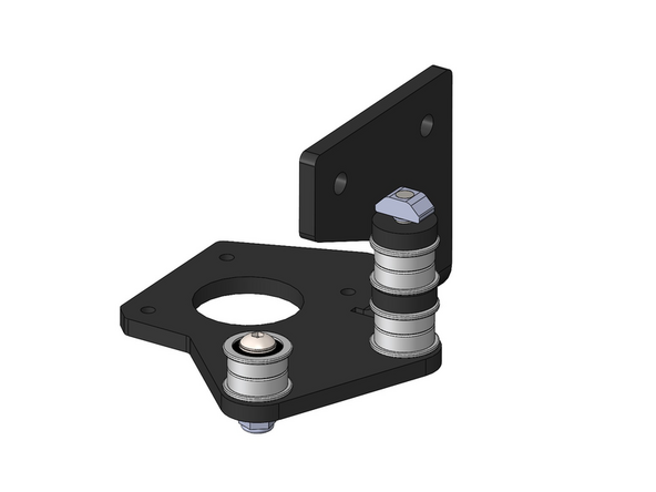
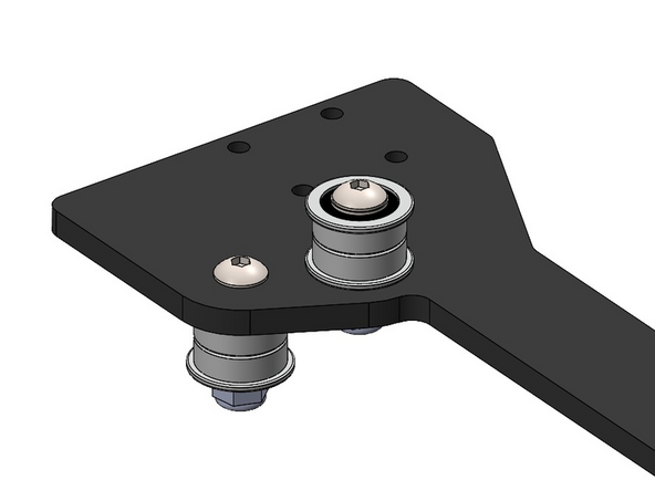
Whilst building Idlers on the motor brackets also build the idlers on the gantry bracket.
-
M4 x 20mm Button Head Bolt
-
M4 x 8 x 0.5mm Shim
-
F624ZZ Bearing
-
M4 Nyloc Nut
-
Make sure that the orientation of the gantry bracket matches that of the image.
-
-
-
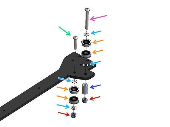
Next build the other two idlers on the other side of the gantry, again make sure that the orientation matches the image.
-
M4 x 20mm Button Head Bolt
-
M4 x 35mm Button Had Bolt
-
M4 x 8 x 0.5mm Shim
-
F624ZZ Bearing
-
M4 x 15mm Spacer
-
M4 Nyloc Nut
-
-
-
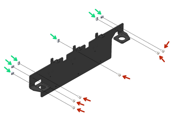
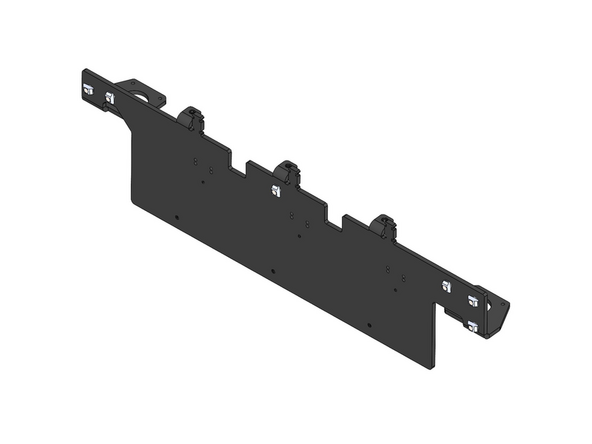
Prepare the print head dock bracket by loosely fastening on:
-
M5 x 10mm Button Head Bolt
-
M5 T-nut
-
-
-
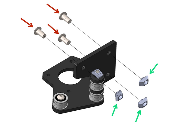
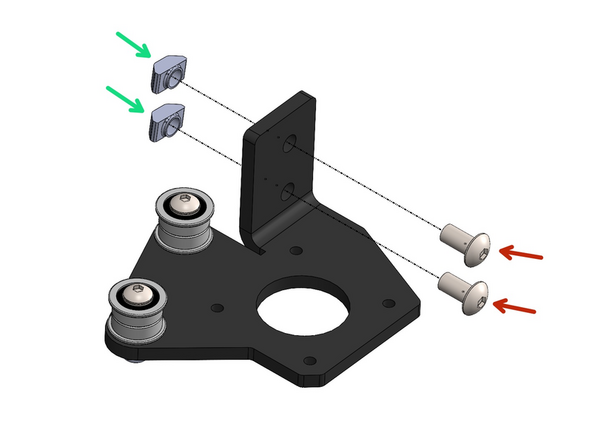
Similarly prepare the two motor brackets as shown:
-
M5 x 10mm Button Head Bolt
-
M5 T-Nut
-
-
-
As shown in the diagram fix onto the frame the Dock and Motor Brackets.
-
When working with T-nuts, align them so they are parallel with the grooves on the extrusion beam. Hold the bracket in position, back the bolt out slightly, and then begin tightening. As you rotate the bolt clockwise, the T-nut should rotate as well, locking into place. Once the T-nut is secure, finish tightening to firmly secure the bracket.
-
Print Head Dock Bracket
-
Front Motor Bracket
-
Tighten the Idler assembly from under the bracket onto the frame also.
-
Rear Motor Bracket
-
Cancel: I did not complete this guide.
2 other people completed this guide.


