
-
-
If you have the DSH assembled, begin by removing the extruders from the top panel.
-
Also remove the spool holders.
-
Make sure to keep a hold of all the fasteners.
-
Place both to one side, we will re-attach them later on.
-
-
-
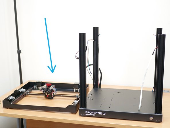
Place the printer on its side as shown.
-
Disconnect the touch screen cables from the mainboard.
-
Remove the touch screen assembly from the base. Keep the washer and nut - they shall be reused.
-
This touch screen is unfortunately not compatible with Klipper and will have to be discarded/repurposed.
-
-
-
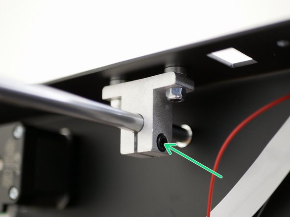
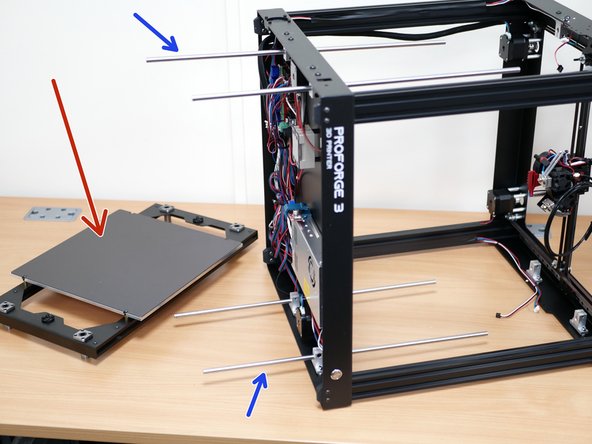
Loosen the bolts on all 8 brackets holding the Z-shafts in place.
-
Pull the shafts free from the platform assembly.
-
Put the platform assembly to one side.
-
Take care of the heated bed cables - note that the bed shown here does not have a heater installed, but yours should do.
-
-
-
Snip away the cable ties holding the extruder and filament sensor cables to the top panel.
-
Do this on both sides.
-
-
-
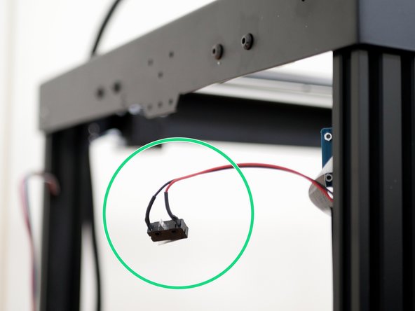
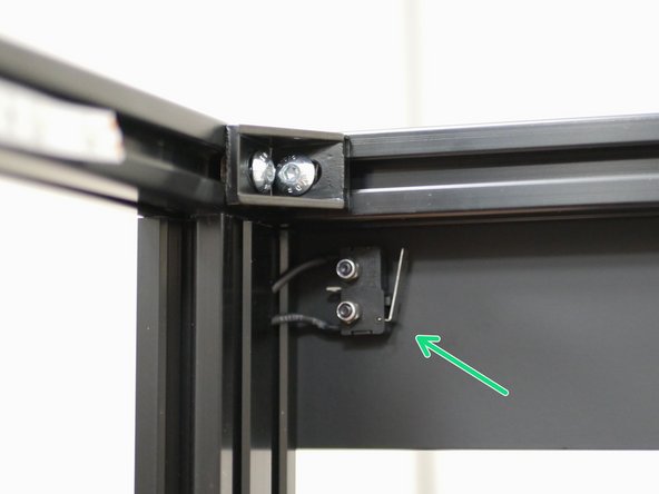
Remove the Y-Endstop from the top panel.
-
Keep the nuts and bolts safe.
-
-
-
Carefully peel the LED light strip away from the top panel, try not to touch the sticky back as you're removing it, it will need to be stuck back onto the extrusion in a later step.
-
-
-
Before starting this step we recommend making some space to the left of the printer, enough to place the top panel down.
-
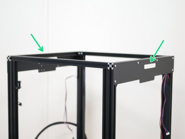
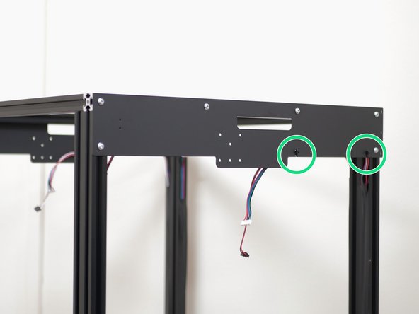
Unfasten the 8x M5 bolts holding the top panel assembly to the extrusions.
-
These bolts can be discarded.
-
Lift the top panel assembly away, and place it to the left of the printer.
-
-
-
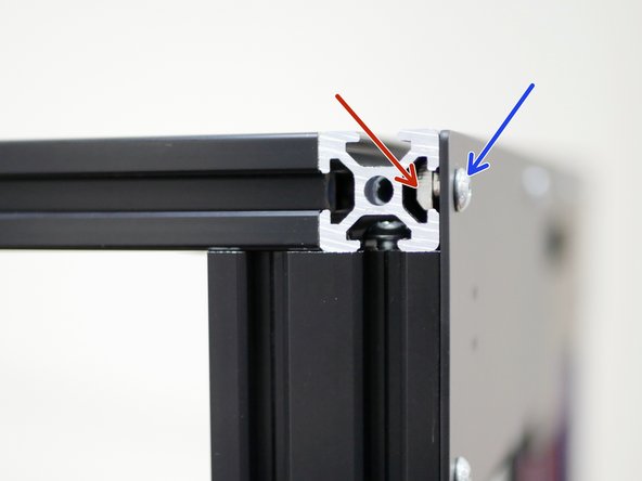
Thread onto the extrusions the included longer M5 x 16mm bolts.
-
Thread them on leaving approx. a 5mm gap.
-
-
-
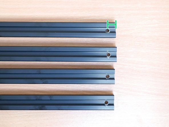
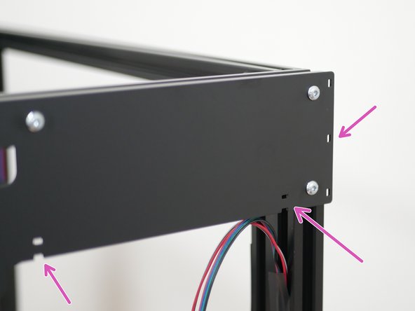
The four long extrusions need x8 5mm holes drilling into them.
-
Each hole should be drilled 10mm from the edge.
-
Both holes on an extrusion should be drilled onto the same side.
-
The accuracy of these holes is not critical, they are only necessary for an allen key to fit through them.
-
-
-
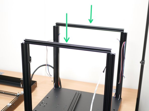
Take the four long 2020 extrusions that you drilled the holes into earlier.
-
Take two of the extrusions and slide them over the heads of the bolt on the front and rear of the the printer.
-
Make sure that you are sliding them on hole side up.
-
Take the remaining two extrusions and slide them over the bolts on the remaining sides.
-
-
-
VERY LIGHTLY tighten the bolts by using an allen key. They will be tightened down later.
-
-
-
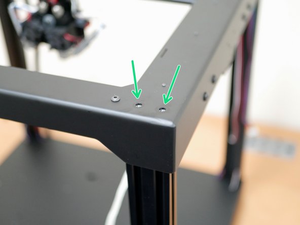
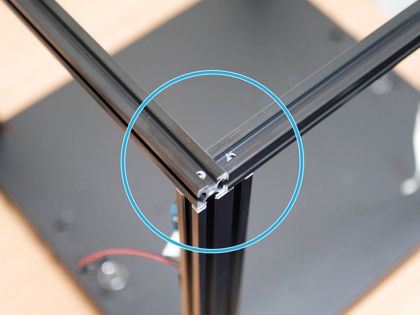
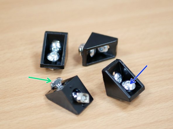
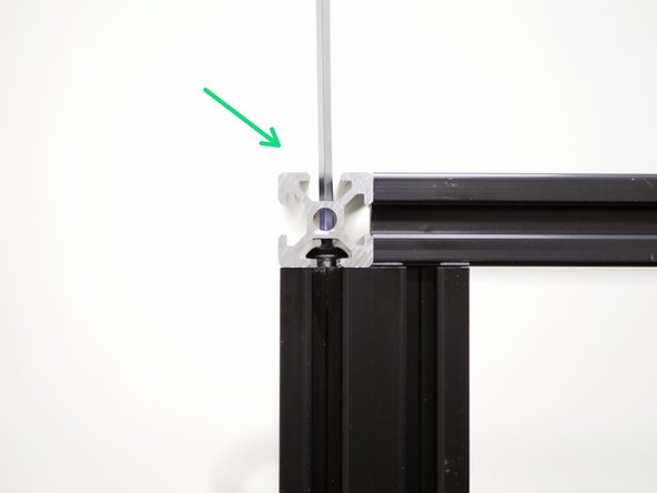
Take four right angle corner brackets and add to them two M5 x 8mm button bolts and M5 T-nuts.
-
M5 x 8mm Button Bolt
-
M5 T-Nut
-
-
-
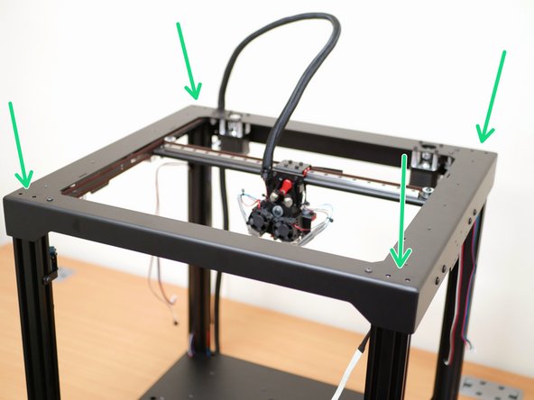
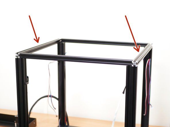
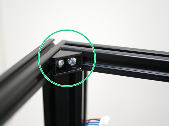
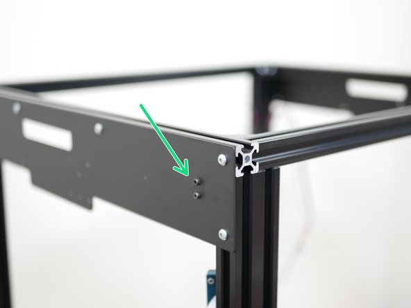
Securely fix the brackets to the internal corners of the printer.
-
-
-
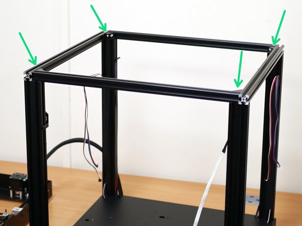
With the corner brackets firmly secured, tighten down the 8 extrusion bolts.
-
-
-
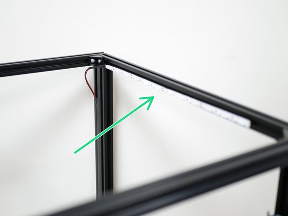
Re-attach the LED strip to the inside of the of the front extrusion as shown.
-
If the strip has lost some of its stickiness we recommend using either double sided tape or a glue gun to secure the strip - but it should be OK.
-
-
-
Install the two side panels as shown.
-
M4 x 6mm Bolt
-
M4 T-Nut
-
Ensure that the panel is orientated correctly with the cable tie mounts pointing to the rear of the machine.
-
-
-
Reattach the Y-Endstop with the same nuts and bolts to the side panel.
-
If you are building the Proforge 3.5 from scratch, this is the endstop with the shorter length cable.
-
-
-
Re-attach the motor and endstop cables to the side panels using cable ties.
-
-
-
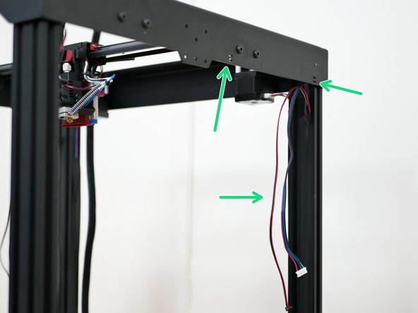
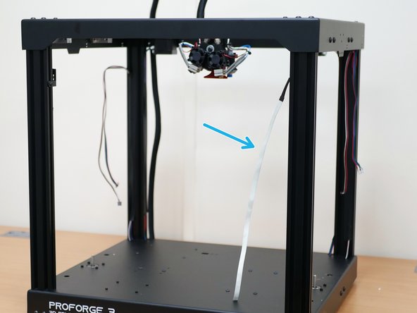
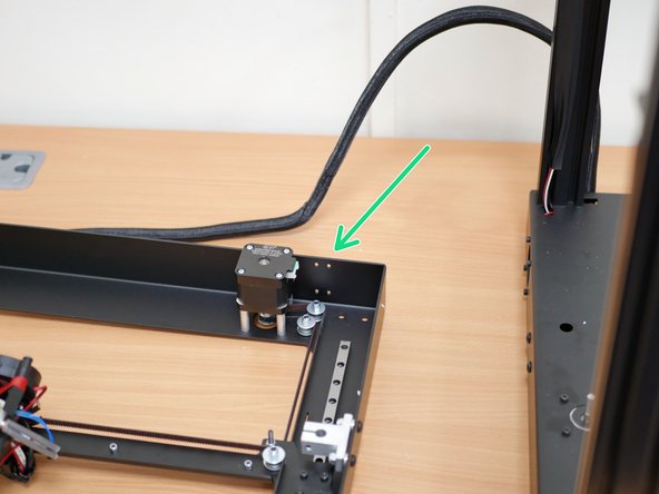
Break the cable ties holding the wiring loom to the rear of the top panel.
-
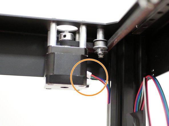
Unfasten the front two idler assemblies.
-
Keep the bearings and washers safe.
-
-
-
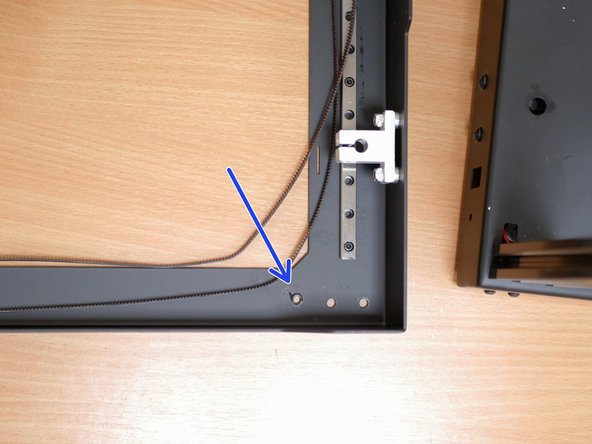
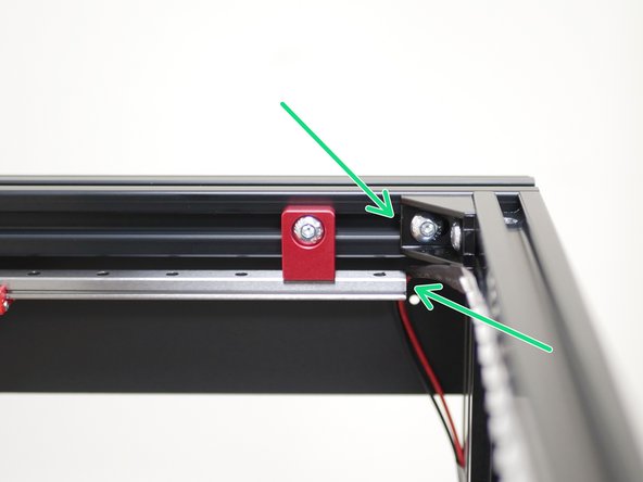
Unfasten the bolts holding the gantry to the rails.
-
Remove the gantry assembly from the top panel.
-
You do not need to undo the belts, they should just fall off the idlers and the motor pulley.
-
-
-
Take the 6 aluminium rail mounts and add to them M5 x 8mm bolts and M5 T-Nuts as shown.
-
M5 x 8mm Button Head Bolt
-
M5 T-Nut
-
-
-
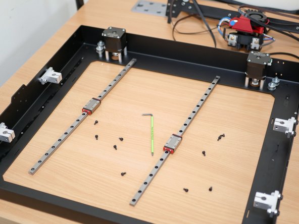
Remove the rails from the Top Panel.
-
These bolts can be discarded.
-
Take care when handling the rails that the carriage does not fall off the rail.
-
-
-
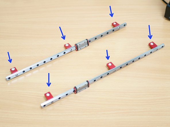
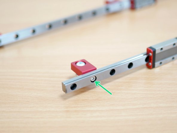
Fix to each of the rails 3 of the aluminium mounts as shown with M3 x 6mm bolts.
-
Space the mounts as shown, with the outer mounts one hole space from the ends, and the third in roughly the centre.
-
-
-
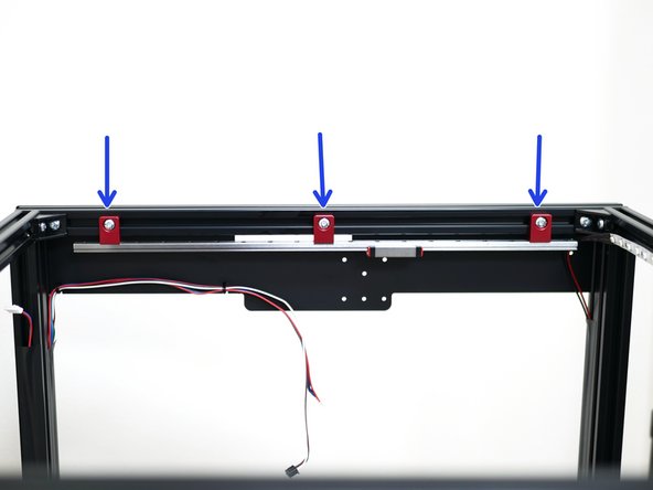
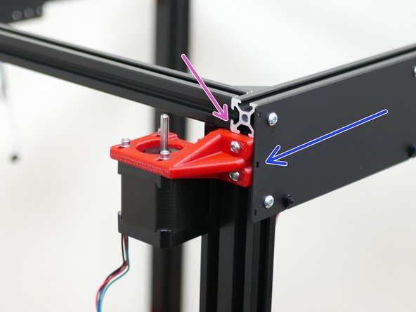
Mount both of the rail assemblies to the side extrusions of the frame as shown.
-
Align the front edge of the rail with the front corner bracket.
-
-
-
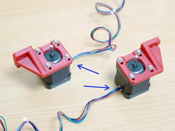
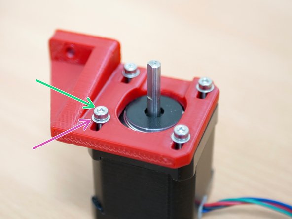
Fix the new X/Y motors to the 3D printed brackets as shown.
-
Orientate the motors as shown with the cables pointing away from the mounting points.
-
M3 x 10mm Bolt
-
M3 Washer
-
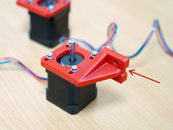
The 3d printed bracket with the notch is designed to fix onto the left side of the printer. Make sure that it is orientated as shown in the third image.
-
-
-
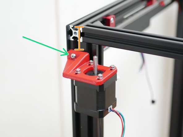
Mount the X/Y Motors to the frame as shown.
-
Use M4 x 12mm bolts and M4 T-Nuts for this.
-
Facing the rear of the machine:
-
The left motor needs to be mounted approx. 33mm from the top extrusion as shown.
-
The right motor needs to be mounted approx. in line with the bottom of the top extrusion as shown.
-
The mount with the notch needs to be mounted onto the right side, the same side as the cable loom comes out of the base.
-
-
-
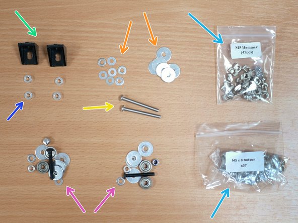
Find the following:
-
Two Corner Brackets
-
Four M4 Spacers
-
M4 Washers and M4 Penny Washers
-
M4 x 40mm Bolts and M4 T-Nuts
-
M5 x 8mm Bolt and M5 T-Nuts
-
The Idler parts from the Top Panel
-
-
-
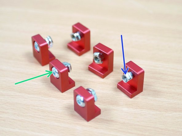
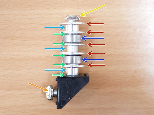
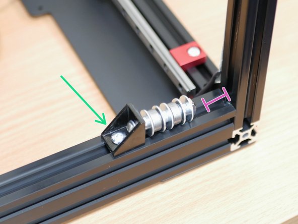
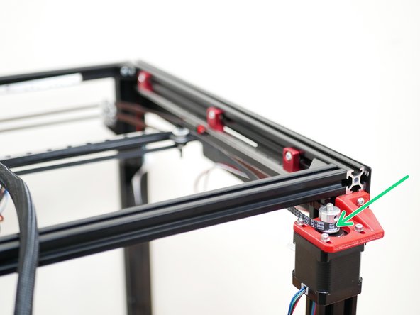
Build two of the front Idler assemblies as shown:
-
M4 x 40mm Button Head Bolt
-
M4 Washer
-
M4 x 4mm Spacer
-
M4 Penny Washer
-
Idler Bearing
-
M4 T-nut
-
M5 x 8mm Bolt and M5 T-Nut
-
-
-
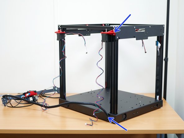
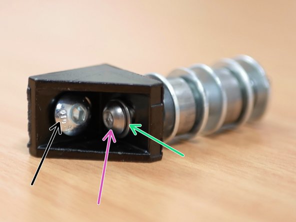
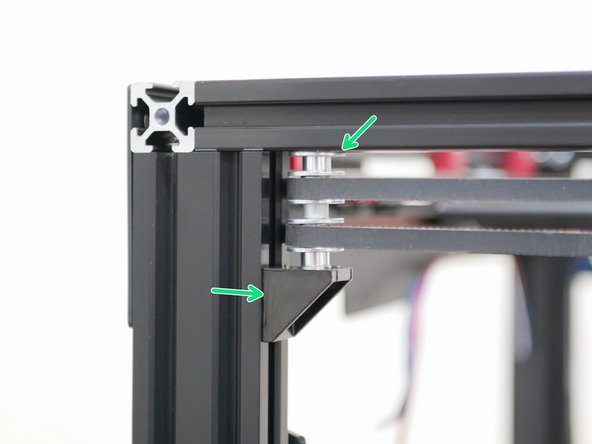
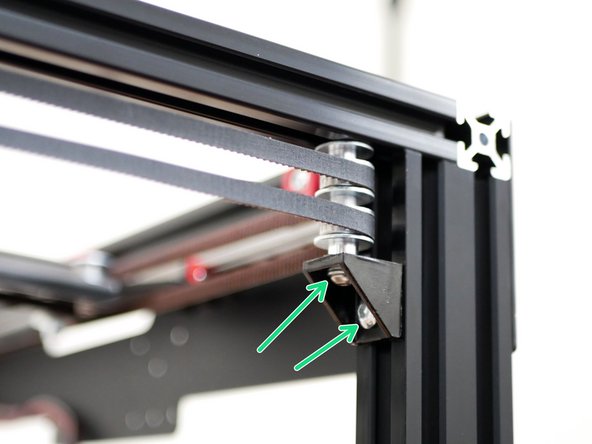
Place the printer to the side again as shown.
-
Install the idler assemblies with just the M5 bolt.
-
Leave a gap at the top of the assembly, this is to allow the belts to drop in.
-
If you have the enclosure, add the top panel now (Stage 07: Enclosure Panels) in order to avoid having to remove the tool head and x-endstop later.
-
-
-
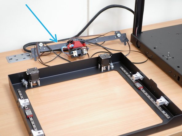
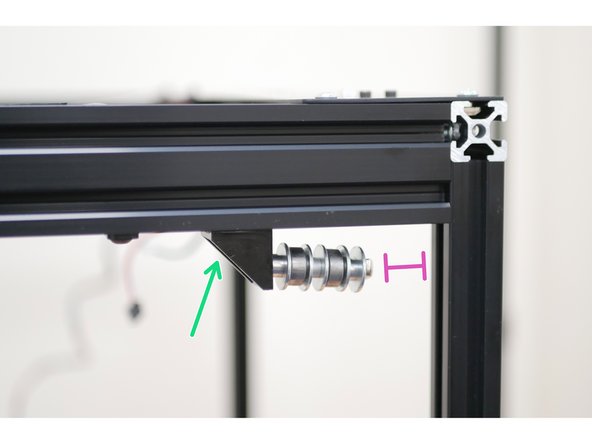
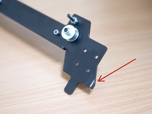
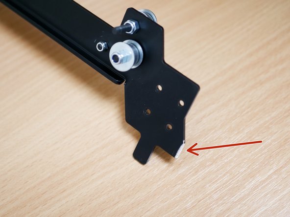
This end of the gantry needs to be filed down by approximately 2-3mm to fit the new top frame.
-
-
-
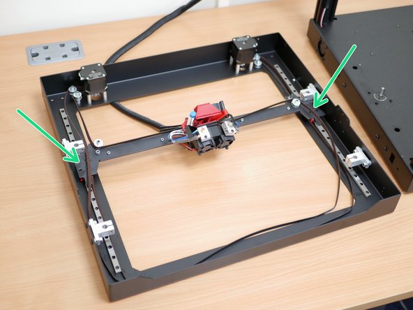
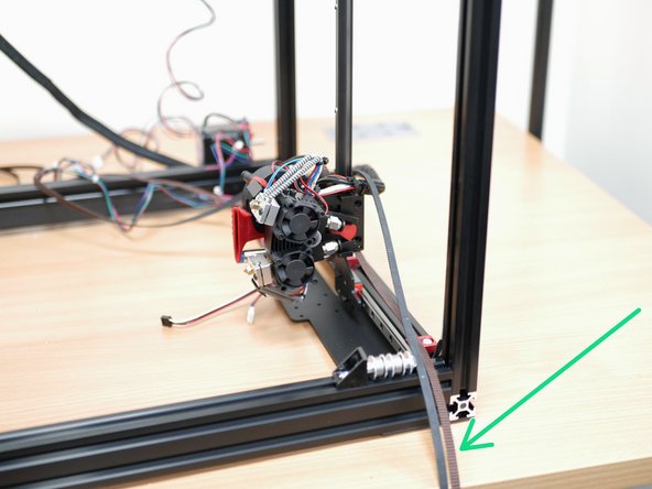
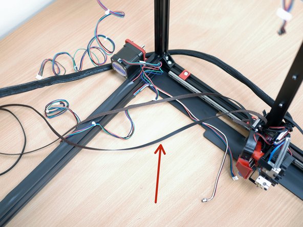
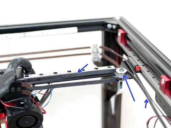
Bring the gantry into the frame.
-
Important - When installing the gantry arrange the belts as described:
-
The top level belt needs to hang out of the front of the printer.
-
The lower level belt need to hang out of the rear of the printer.
-
-
-
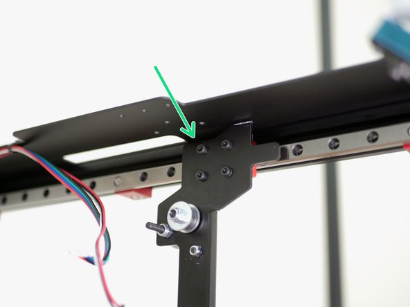
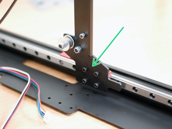
Fix the gantry to the Y-rail carriages using the original M3 x 6mm bolts.
-
-
-
Upright the printer.
-
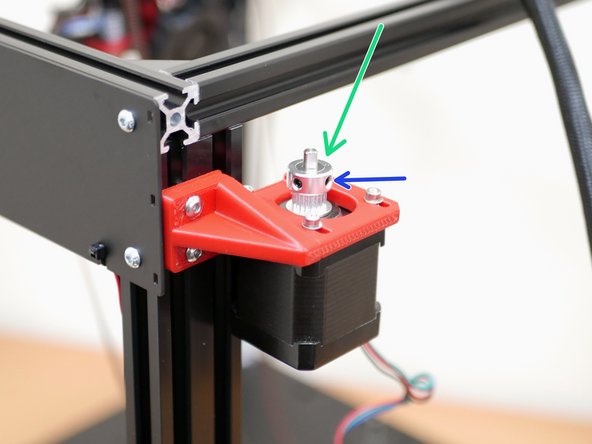
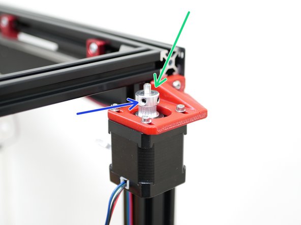
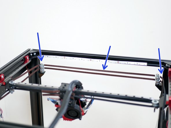
Retrieve the belt pulleys from the top panel assembly.
-
Drop them onto the new motors as shown.
-
It's important the grub screw side is facing upwards.
-
-
-
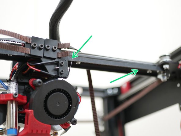
With the rear of the printer facing you take the bottom level belt and loop it around the bearing on the gantry as shown.
-
Next drop the belt onto the front idlers.
-
-
-
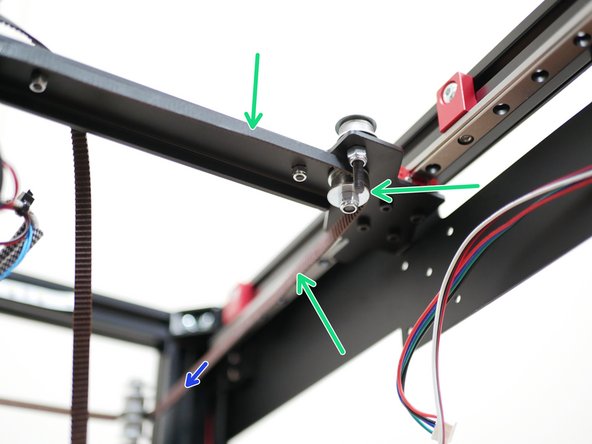
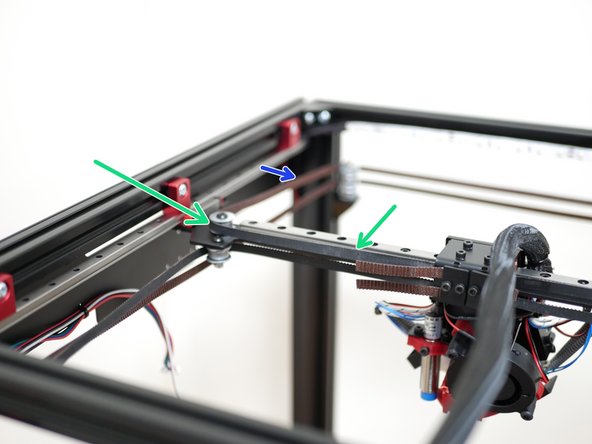
From the front idlers loop the belt around the pulley on the rear motor.
-
Take the remaining belt and loop it around the idler on the gantry.
-
-
-
Repeat the same process for the top level belt by first looping it around the bearing on the left side of the gantry as shown.
-
Next drop the belt onto the front idlers.
-
-
-
From the front idlers loop the belt around the pulley on the rear motor.
-
Take the remaining belt and loop it around the idler on the gantry.
-
-
-
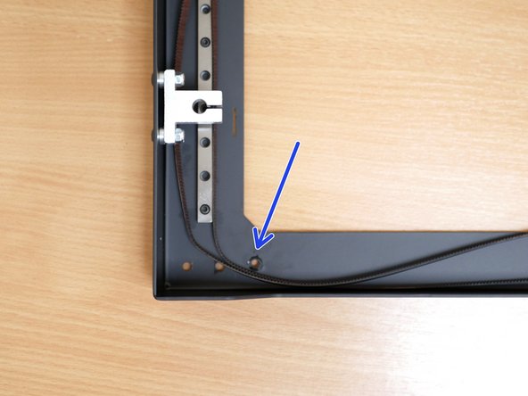
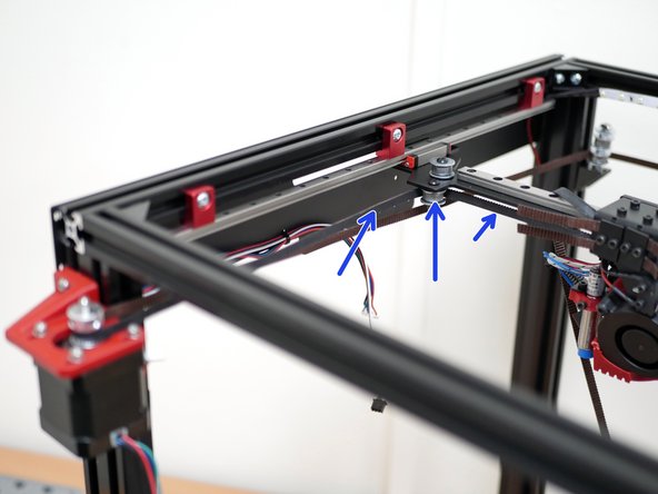
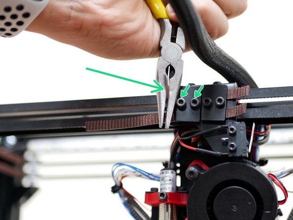
Use a pair of needle nozzle pliers to tighten the belts.
-
Grip the belts with the pliers and twist against the carriage to tighten.
-
Before starting, make sure that the clamp is tightened down enough to allow you to pull more belt through, but not allow the belt to slip back.
-
Trim away excess belt leaving approximately half an inch.
-
-
-
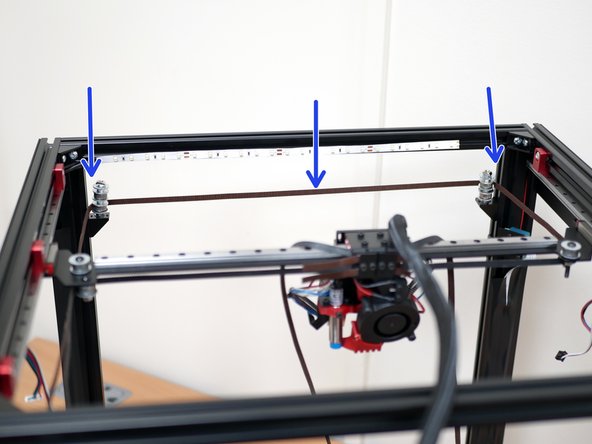
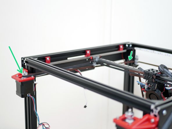
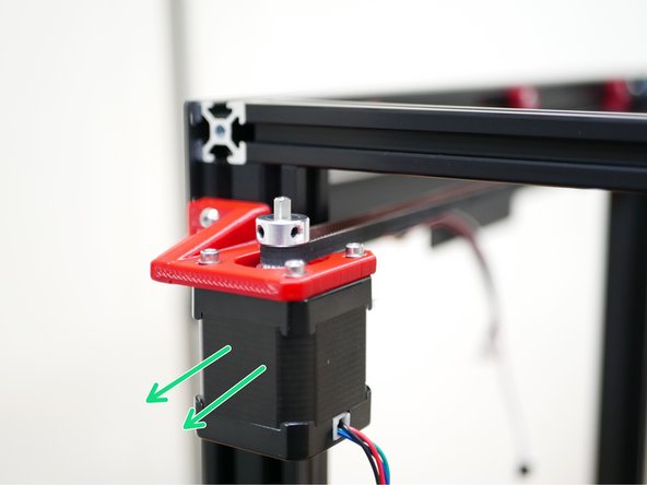
Pull the motors back to tension the belt further.
-
The belts should be guitar string tight, do not over tighten the belts with excessive force.
-
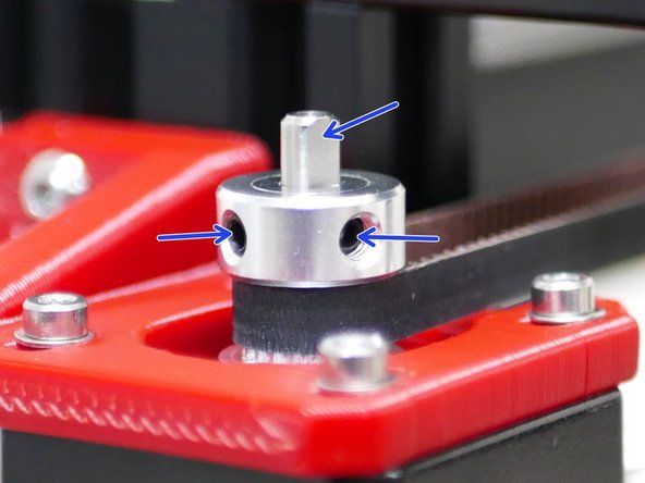
Finally tightened the grub screws on the pulleys to secure them to the motor shaft.
-
Make sure one of the grub screws is being tightened against the flat of the shaft.
-


Cancel: I did not complete this guide.
2 other people completed this guide.
