
-
-
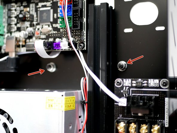
Fix the Endstop onto the base as shown.
-
Two M3 x 14mm Bolts
-
Two M3 x 5mm Spacers
-
Two M3 Nyloc Nuts
-
-
-
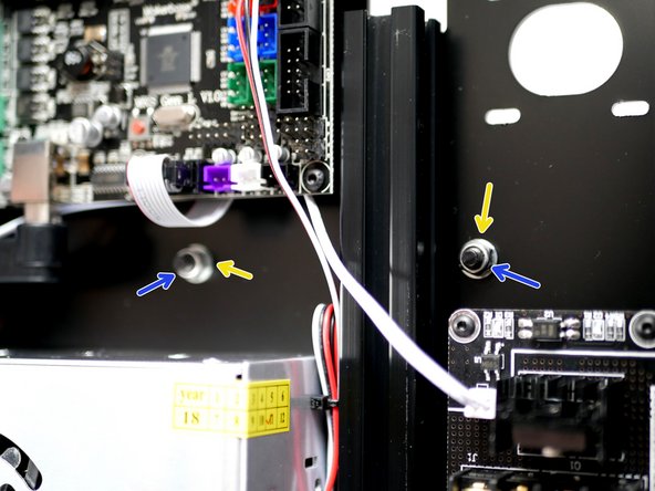
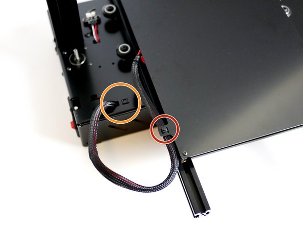
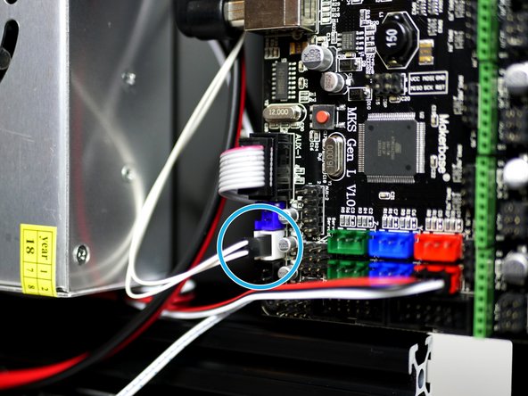
Connect the Endstop cable and feed the other end into the base and route it to the control board.
-
Connect the Endstop to the "X+" position as shown in the second image.
-
Tidy the excess cable with cable ties and tuck in between the power supply and support beam.
-
-
-
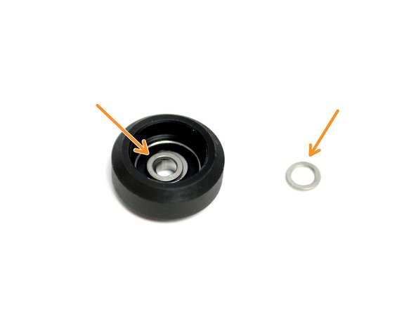
Create the roller assemblies by pressing two 625zz bearings into a delrin roller wheel with a 1mm shim between them.
-
Delrin Roller Wheel
-
625zz Bearing
-
Precision Shim
-
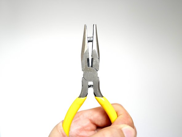
You may need to use a pair of pliers to force the bearings into the delrin wheel.
-
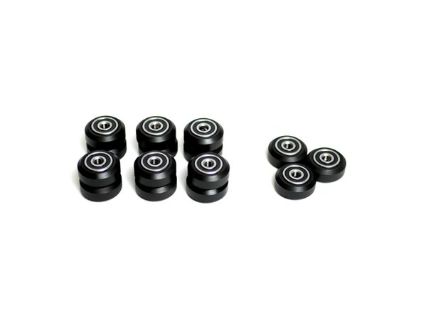
You should have 12 in total for the Proforge 2 and 15 for the Proforge 2S.
-
-
-
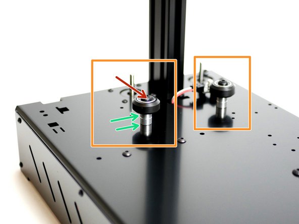
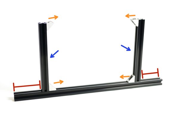
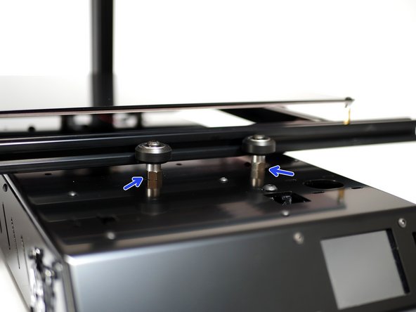
Install two roller wheels to the rear of the base.
-
Two M5 x 35mm Bolts
-
Four M5 Aluminium Spacers (x2 per bolt)
-
Two M5 Nyloc Nuts
-
Tighten firmly.
-
-
-
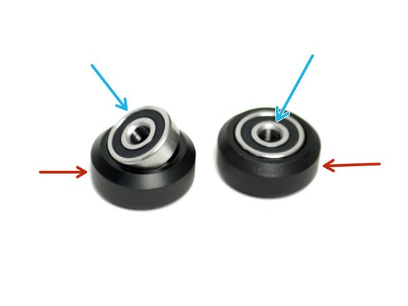
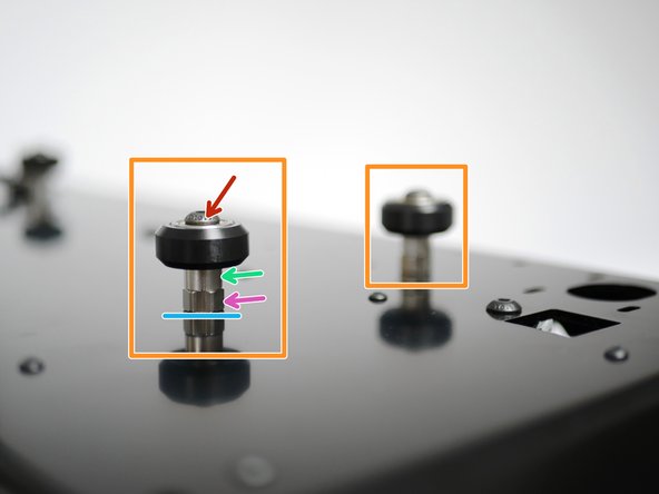
Install two roller wheels at the front of the base. Fix loosely with eccentric spacers and M5 washers:
-
Two M5 x 35mm Bolts
-
Two M5 Aluminium Spacers
-
Two M5 Eccentric Spacers
-
Two M5 Washers
-
Two M5 Nyloc Nuts
-
Fix loosely so that that the eccentric spacers are still free to rotate.
-
Below the blue line is just a reflection.
-
-
-
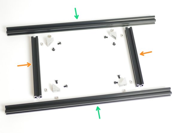
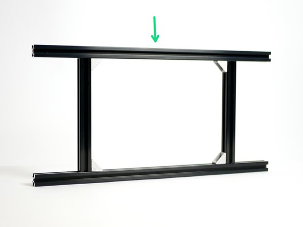
Assemble the platform frame, keep it as square and flat as possible. Avoid gaps.
-
Two 2020 x 450mm Extrusions
-
Two 2020 x 189mm Extrusions
-
Four Corner Brackets
-
Eight M5 x 8mm Bolts
-
Eight M5 T-Nuts
-
See next steps for assembly process...
-
-
-
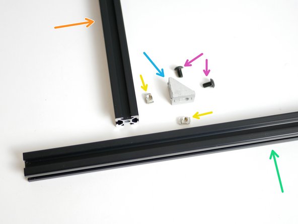
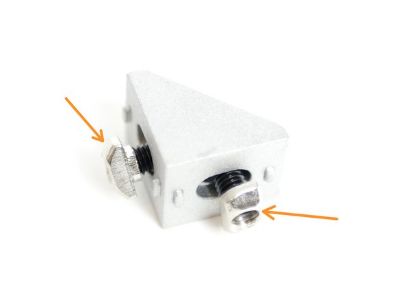
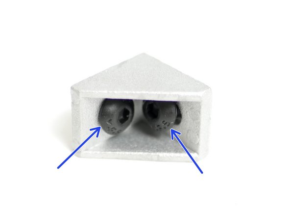
Prepare four corner brackets with M5x8mm bolts and M5 t-nuts as shown in the images.
-
Two M5 x 8mm bolts each
-
Two M5 T-Nuts each
-
-
-
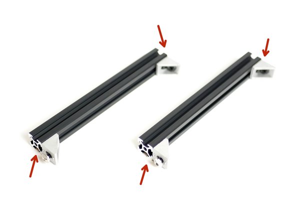
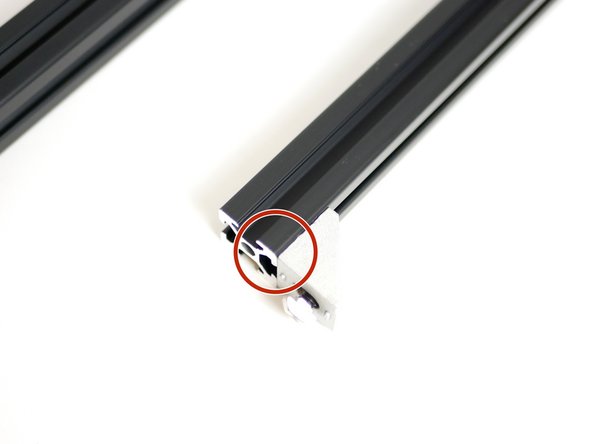
Fix the corner bracket assemblies on to the two 2020x189mm beams as shown in the image.
-
It's important that the corner brackets are smooth against the end of the 2020x189mm beam.
-
-
-
Fix the two 2020x189mm beams on to a 2020x450mm beam.
-
Make sure that the corner brackets are facing inwards.
-
Make sure that both 189mm beams are 75mm in from the ends of the 450mm beams.
-
Finally secure the second 2020x450mm beam to complete the platform assembly.
-
-
-
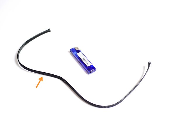
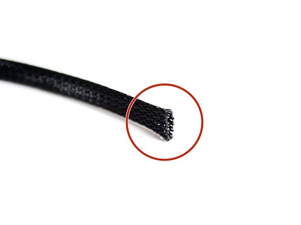
Cut 50CM of the Braided Sleeving.
-
Use a lighter to melt the ends to prevent fraying.
-
-
-
Steps 12 - 15 show how to install the new aluminium heated platform.
-
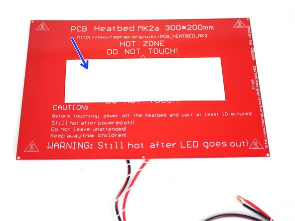
Steps 16 - 21 show how to install the old red heated PCB platform.
-
Complete accordingly and continue with step 22 when done.
-
-
-
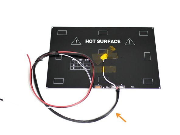
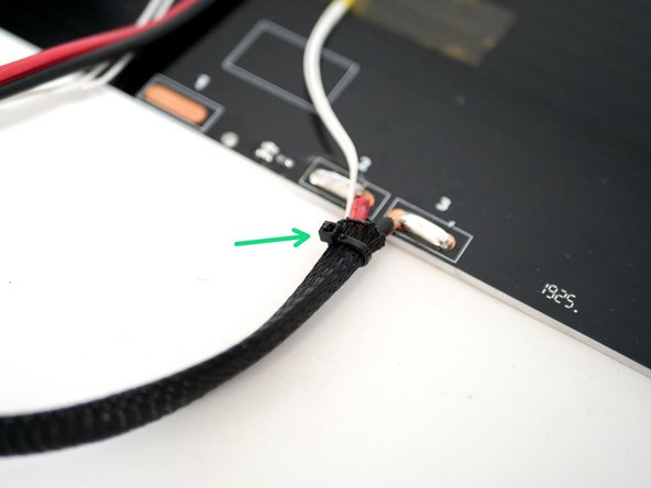
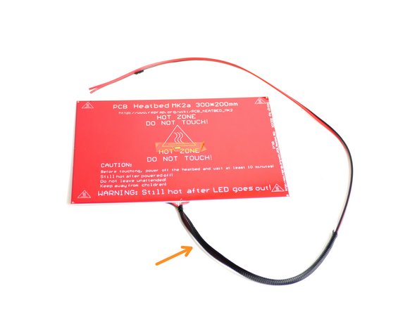
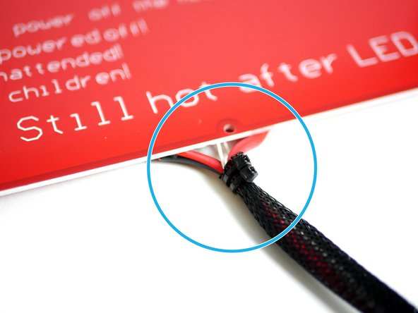
Slide the braided sleeving onto the heated bed cables.
-
Tie the end with cable ties to hold in place.
-
-
-
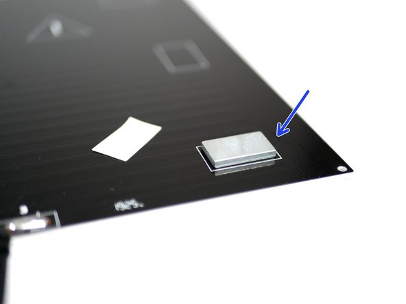
The included magnets are very strong and should be handled with care. Magnets are also brittle and should never be slammed together. Keep clear of metal objects. Always slide a magnet to separate it from a surface.
-
Take one of the double sided stickers and peel one side. Fix the sticker onto one of the magnets.
-
Carefully slide the magnet off the stack. The easiest way to remove a magnet from the stack is to first twist it and then slide it off.
-
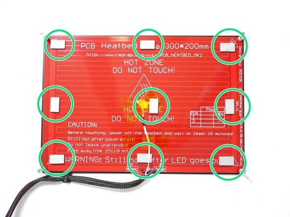
Peel the other side of the sticker and fix the magnet to the back of the heated bed/platform.
-
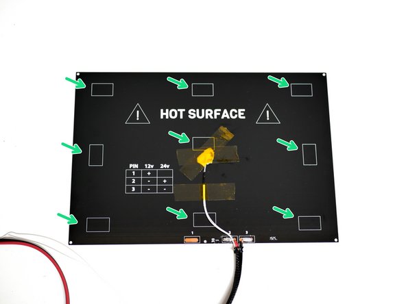
Arrange the magnets according to the boxes marked on the platform.
-
Apply the sticker to the same side/pole of each magnet. This is easy to do by making sure that each sticker is continuously stuck to the magnet at the top of the stack.
-
-
-
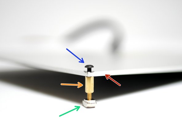
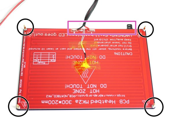
Prepare the brass stand-offs like shown:
-
Four M3 T-Nuts
-
Four Brass Stand-offs
-
Heated Bed
-
Four M3 x 8mm bolts
-
The T-nut should be on the black side with the text (bottom) of the heated bed.
-
Install loosely, do not tighten yet!
-
-
-
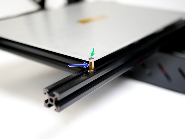
The aluminium heated bed is mounted directly onto the platform frame.
-
For a single Hotend setup install onto the centre of the frame.
-
For the DSE setup install 75mm from the right edge of the platform frame.
-
Once happy with the positioning, turn the brasss stand-off's first to secure them to the frame.
-
Next tighten the M3 bolts to fix the platform onto the stand-offs.
-
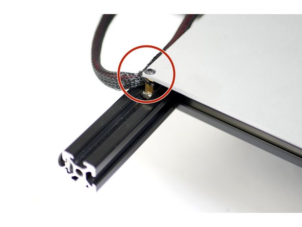
Once the platform is secured cable tie the cables to the top left stand-off.
-
-
-
Slide the braided sleeving onto the heated bed cables.
-
Tie the end with cable ties to hold in place.
-
-
-
Peel off one side of the adhesive sticker and stick it to the centre of the flat side of the heated bed
-
Peel the backing paper off the double sided adhesive paper and press the heated bed on to the metal platform.
-
Make sure the cables face upwards and are on the same side as the cable tie tab.
-
-
-
Compress each of the springs with pliers to reduce their length, this will make it easier to install them.
-
-
-
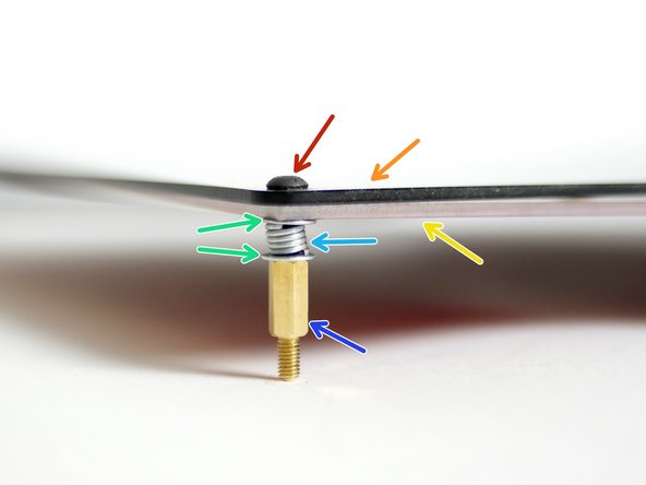
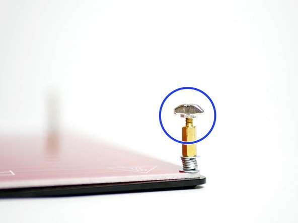
Assemble the brass standoffs to the four corners of the platform - Tighten firmly so that the spring is fully compressed:
-
Four M3 x 14mm bolts
-
Platform
-
Heated Bed (Proforge 2S only)
-
Four M3 Washers
-
Four Platform Springs
-
Four Brass M3x10mm Standoffs
-
-
-
The included magnets are very strong and should be handled with care. Magnets are also brittle and should never be slammed together. Keep clear of metal objects. Always slide a magnet to separate it from a surface.
-
Take one of the double sided stickers and peel one side. Fix the sticker onto one of the magnets.
-
Carefully slide the magnet off the stack. The easiest way to remove a magnet from the stack is to first twist it and then slide it off.
-
Peel the other side of the sticker and fix the magnet to the back of the heated bed/platform.
-
Arrange the magnets like shown in the third image.
-
Apply the sticker to the same side/pole of each magnet. This is easy to do by making sure that each sticker is continuously stuck to the magnet at the top of the stack.
-
-
-
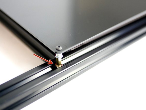
Screw onto the ends of the four brass standoffs an M3 T-Nut.
-
Fix the platform assembly onto the centre of the platform frame.
-
DSE: If you're building with the Dual Switching Extruder, mount the platform 75mm from the left of the extrusion.
-
Make sure the platform is stable and firmly mounted onto the frame.
-
-
-
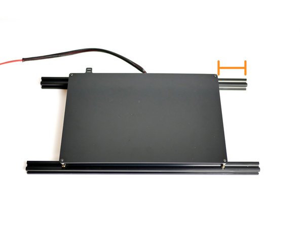
Slide the Platform assembly in between the four rollers on the base.
-
Rotate the front eccentric spacers with a pair of pliers so that the platform assembly slides smooth and stable.
-
Once the platform is completely secure against the rollers tighten the M5 Nyloc Nuts on the underneath of the platform for the front two rollers.
-
The platform should be able to slide smoothly with the rollers turning as it moves against them.
-
-
-
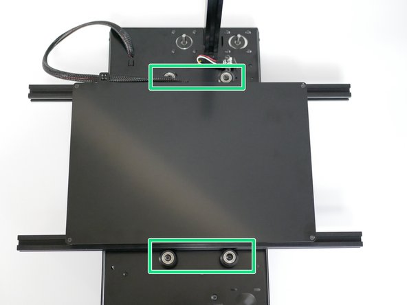
Fix the heated bed cables to the platform with cable ties.
-
Feed the cables through the Base and cable tie them in place.
-
Make sure to leave enough slack in the cable between the tab on the platform and the hole in the base for the platform to reach its extremities on the rollers.
-
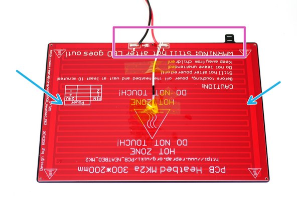
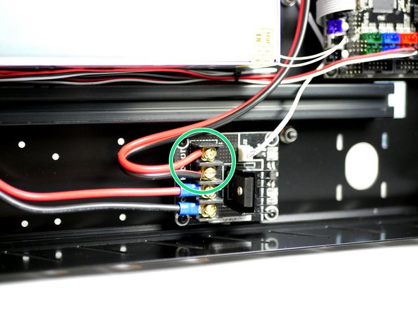
Wire the heated bed power cables to the MOSFET terminals like shown in the second image.
-
Take care to plug the red/black cable to the correct terminals on the MOSFET.
-
Plug the thermistor cable into the electronics board as shown in the third image.
-
-
-
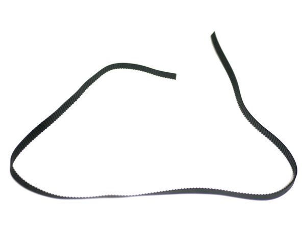
Cut 65CM of the GT2 Timing Belt.
-
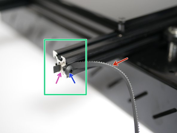
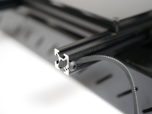
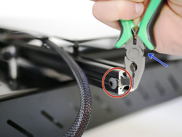
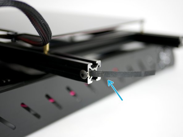
Fix one end to the top right corner of the platform frame.
-
One M5 x 8mm bolt
-
One M5 T-Nut
-
Make sure the teeth are facing inwards.
-
This is a tight fit for the T-Nut, it will need to be forced in quite firmly. A hammer in some cases may even be needed to knock it in.
-
-
-
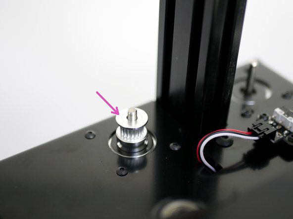
Drop a Pulley onto the shaft of the x-axis motor. Do not tighten the set screws yet.
-
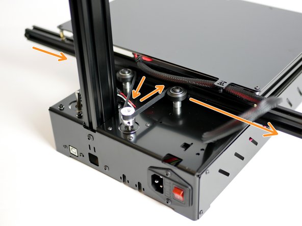
Weave the belt around the rollers and puley as shown in the image.
-
Fix the other end of the belt to the platform frame with an M5 x 8mm bolt and M5 T-Nut the same as before on the other side.
-
Use a pair of pliers to pull the belt tight to tension it, whilst holding the tension tighten down the M5 bolt.
-
-
-
Trim off any extra belt.
-
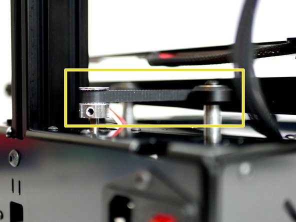
Move the pulley so that the belt runs horizontally.
-
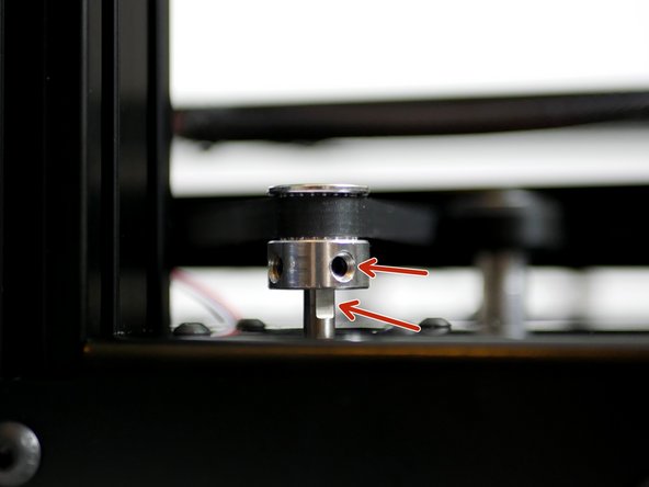
Tighten down the two set screws.
-
Make sure that one of the set screws is tightened against the flat part of the motors shaft.
-
-
-
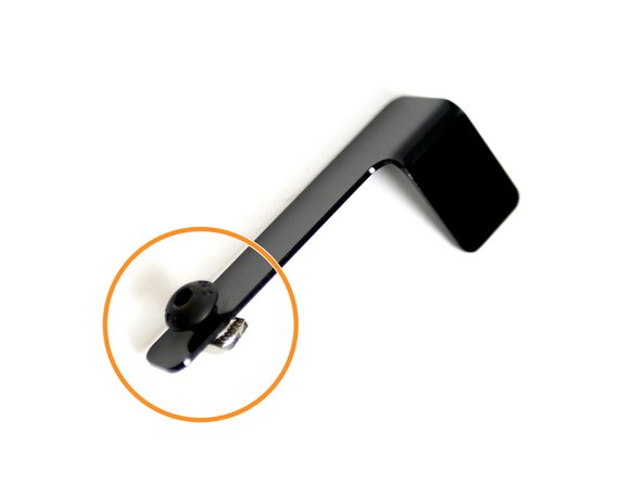
Prepare the endstop trigger with an M5x6mm bolt and M5 T-Nut.
-
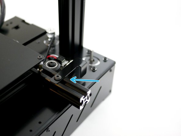
Loosely fix onto the top right side of the platform frame.
-
Its position will be adjusted later.
-


Cancel: I did not complete this guide.
27 other people completed this guide.
