
-
-
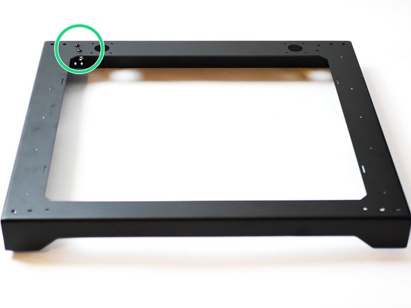
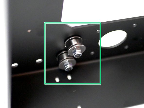
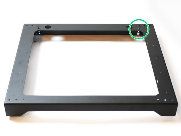
Fix the four metal brackets to the sides of the top panel.
-
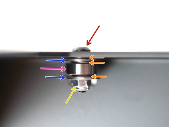
Bracket
-
M5 x 3mm Spacer
-
M5 x 16mm Button
-
M5 Nyloc Nut
-
Do not tighten yet, leave the bracket fixed loosely.
-
Make sure the bolt on the bracket is facing outwards and away from the centre of the base panel.
-
-
-
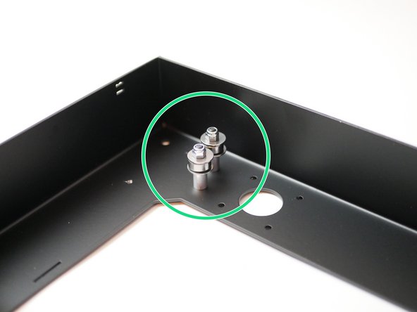
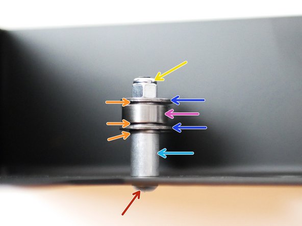
Install the two idler assemblies onto the rear left of the top panel as shown.
-
M4 x 18mm Button
-
M4 Washer
-
M4 Penny Washer
-
624zz Bearing
-
M4 Nyloc Nut
-
-
-
Install the two idler assemblies onto the rear right of the top panel as shown.
-
M4 x 30mm Button
-
M4 x 12mm Spacer
-
M4 Washer
-
M4 Penny Washer
-
624zz Bearing
-
M4 Nyloc Nut
-
-
-
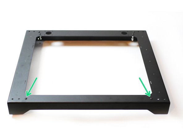
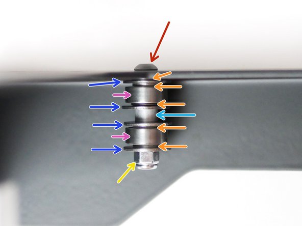
Install the two idler assemblies onto the front of the top panel as shown.
-
M4 x 30mm Button
-
M4 Washer
-
M4 Penny Washer
-
624zz Bearing
-
M4 x 4mm Spacer
-
M4 nyloc Nut
-
Note, it's a little hidden in the photo, but there is another M4 washer between the panel and the top penny washer.
-
-
-
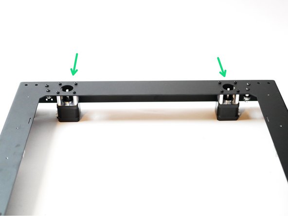
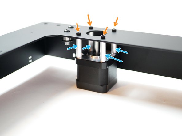
Install the two 0.9 degree stepper motors to the rear of the top panel as shown.
-
M3 x 30mm Cap
-
M3 x 25mm spacer
-
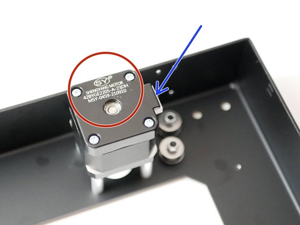
Orientate the motor so that the cable header is pointing towards the idler assemblies.
-
Double check it's the 0.9 degree motors that you are installing. 42BYGE2205
-
-
-
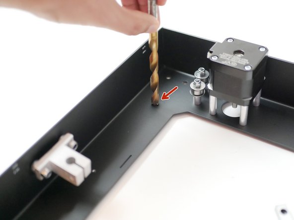
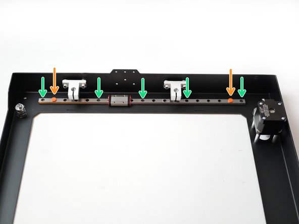
Use an oversized drill bit to carefully clear any burr left over from the threading of the rail mounting holes.
-
Remove a rail from its packaging and move the red carriage stoppers in one hole space.
-
Secure the rail to the top panel as shown with five M3 x 6mm Cap bolts.
-
Repeat the process for the rail on the other side of the top panel also.
-
Make sure that the carriage never falls off the rail.
-


Cancel: I did not complete this guide.
8 other people completed this guide.
