-
-
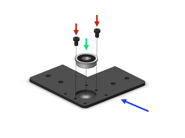
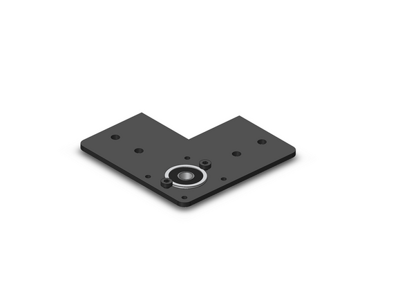
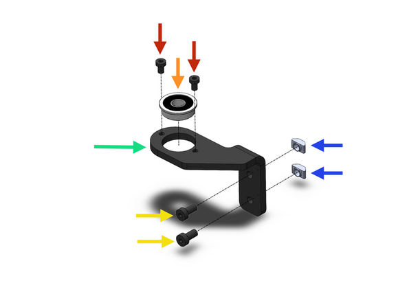
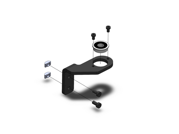
Prepare four z-motor brackets as shown.
-
Z-Motor Bracker
-
F608ZZ Bearing
-
M4 x 6mm
-
-
-
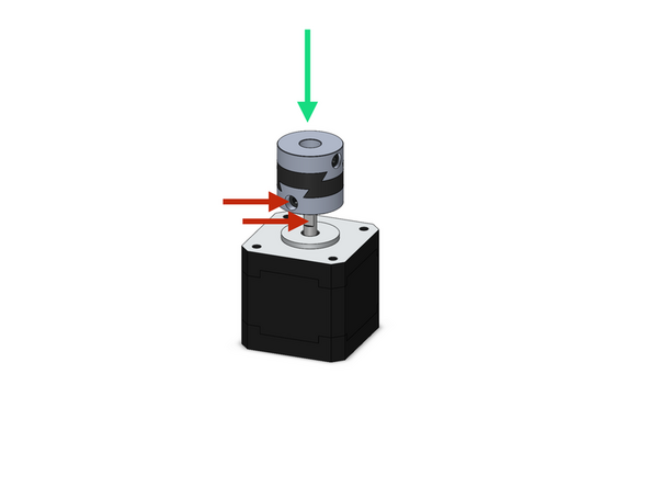
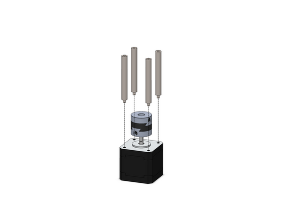
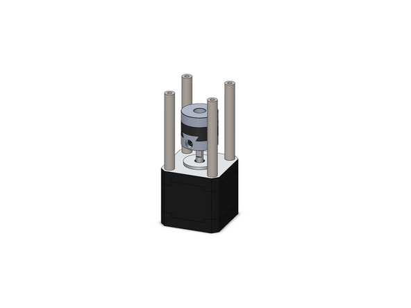
Secure onto the four z-motors an oldham coupling.
-
Secure the coupling to the flat of the motor shaft
-
Z-motors are the smaller NEMA 17 motors
-
Secure to the motors 4x M3x55mm stand-offs.
-
-
-
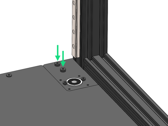
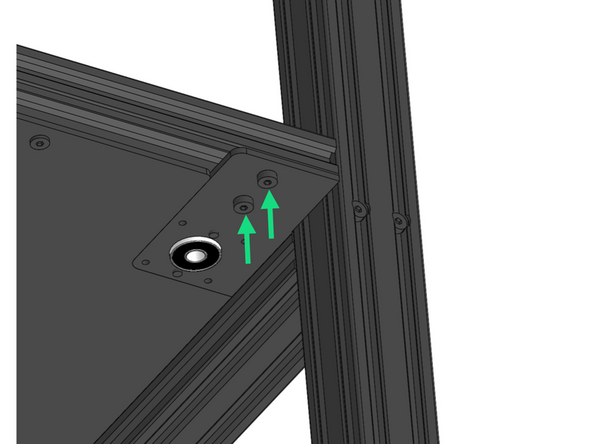
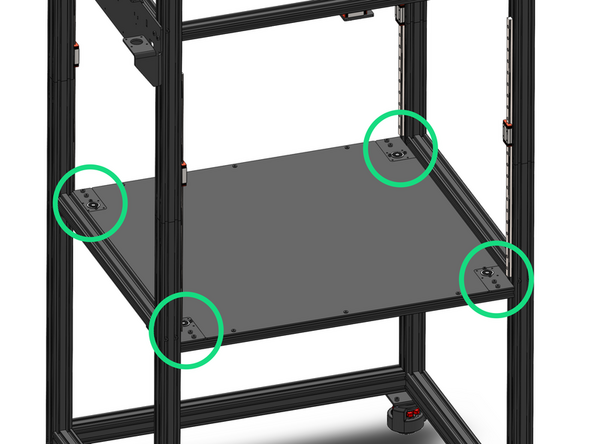
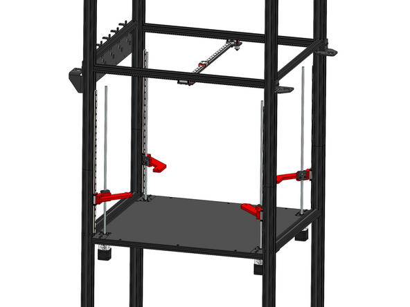
Secure the four z-bracket assemblies to the frame with M5x8mm bolts and M5 T-nuts.
-
Loosen the bolts holding the enclosure panel as the tolerance between it and these brackets is tight. Tighten again once brackets are secure.
The tolerances between the bottom panel and the Z-brackets is too tight. I had to plane the corners of the panel to ensure a perfect fit. You need to reduce the panel's dimensions.
Olivier Bernadou - Open Reply
1. The tolerances between these Z-brackets and the bottom panel of the enclosure (which I installed earlier in Step 6 of Stage 1) are extremely tight. I essentially had to detach the bottom panel, insert the Z-brackets and then reattach the bottom panel. Perhaps installation of the enclosure's bottom panel should be moved to follow this step.
2. I think the note about ensuring the motor connectors face the rear of the machine might be more appropriate in the next step.
+1 had to loosen the panel, install z brackets, retighten panel. Highly recommend that panel installation step moves to after this step
My bottom panel did not fit properly once the Z-brackets were installed. I would assume that the brackets are more important to the operation of the printer than the bottom panel laying perfectly flush with them.
-
-
-
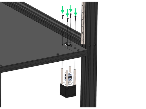
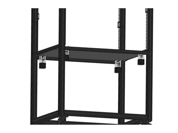
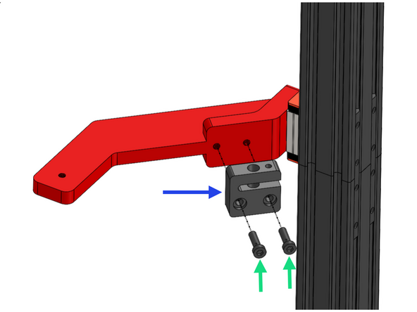
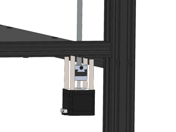
Fix the four z-motor assemblies to the brackets.
-
M3 x 12mm Bolt
-
Ensure the motors connectors face the rear of the machine.
I wound up rotating the right front and left rear motors so that their connectors face forward. That way the right-front cable ducks directly into the extrusion channel (could have had it point right, instead) and the left-rear cable goes right up through the cutout in the enclosure bottom panel.
Phil Salkie - Open Reply
-
-
-
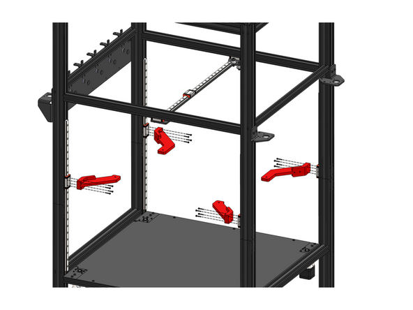
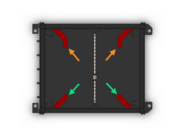
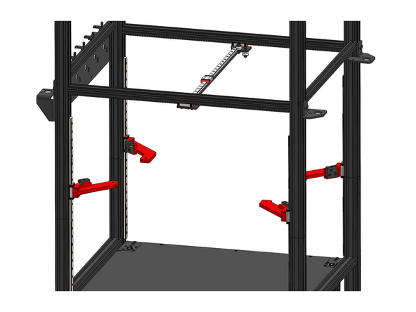
Fix to the rails the Z-carriages with 4 M3x16mm bolts.
-
Front Z-Carriage (Smaller)
-
Rear Z-Carriage
Its easier to put lead screw nut in step 6 on the carriage arms before attaching to rails
Kevin McGraw - Open Reply
-
-
-
Fix a lead screw nut to each z-carriage.
-
Lead Screw Nut
-
M5 x 18mm Bolt
-
The set screw side of the nut should point upwards.
I also find this fitment out of sequence, as I fit the "lead screw nut" to the lead screw and adjust the grub screw to take out the play, as it's easier to preload correctly. Personally, I'd spin the plastic part on the lead screw, insert the shafts at Step 7, and after adjusting the tolerance using the grub screw, spin the lead screw to position over the build plate supports.
mike crane - Open Reply
-
-
-
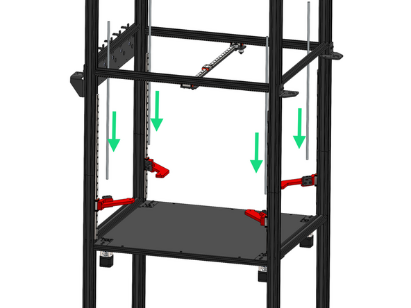
Thread the four lead screws through the nuts and down into the couplings.
-
Secure the lead screws to the couplings.
Turned out two opposite corners needed shims, two don't. Something's probably trapezoidal by about half a millimeter...
Phil Salkie - Open Reply
When you're assembling this, keep the motor mount plate z-nut screws slightly loose, the bearing mount screws slightly loose, and the lead screw nut mounts slightly loose. Once the lead screw is into the coupling, keep checking that the lead screw turns very freely and the red arm moves up and down smoothly. I found that on one corner, no matter how loose I made everything else, as soon as I tightened the lead screw nut to the red arm, it bound up the shaft. The fix was to use a 5mm washer as a shim on each screw - so the lead screw is a fraction of a mm spaced off the red arm - now with everything tightened back up, it's smooth as silk. (The other three all tightened up just fine, so something's off just a hair somewhere on that one corner - but I sure don't see what it might be.) Of course, once you tighten the coupling onto the lead screw, you've got the motor's internal resistance to fight the motion, but that's expected.
Phil Salkie - Open Reply
-
-
-
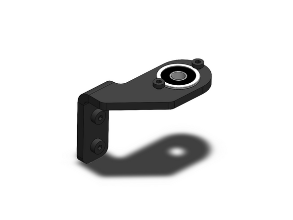
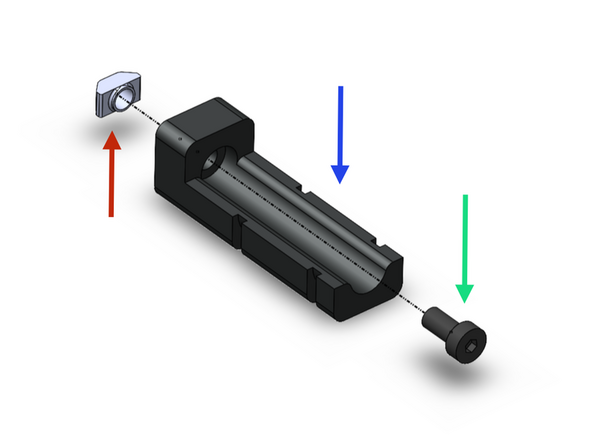
Prepare the lead screw brackets as shown.
-
Note that the brackets are mirrored, you should have two types of each.
-
Lead Screw Bracket
-
F608ZZ Bearing
-
M4 x 6mm Bolt
-
M5 x 10mm Bolt
-
M5 T-Nut
-
-
-
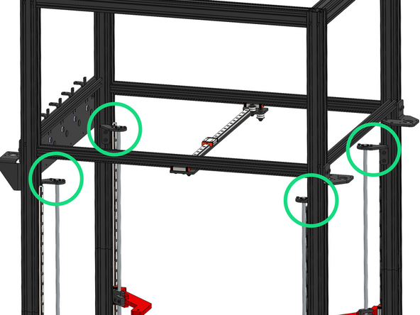
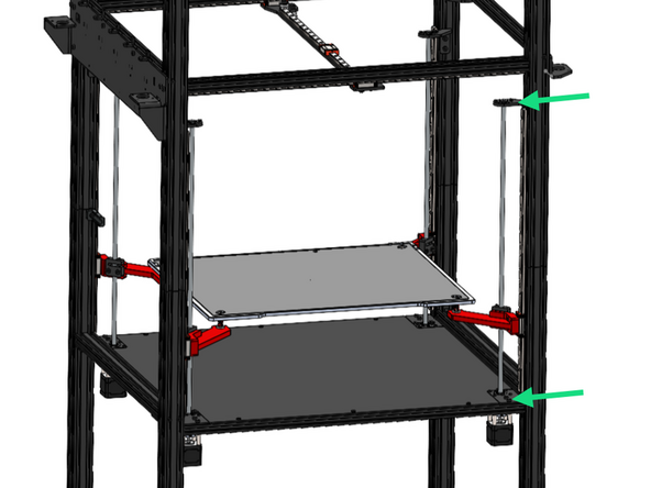
Fix the four lead screw bracket assemblies onto the frame.
-
Take care to orientate these brackets exactly as shown in the image.
-
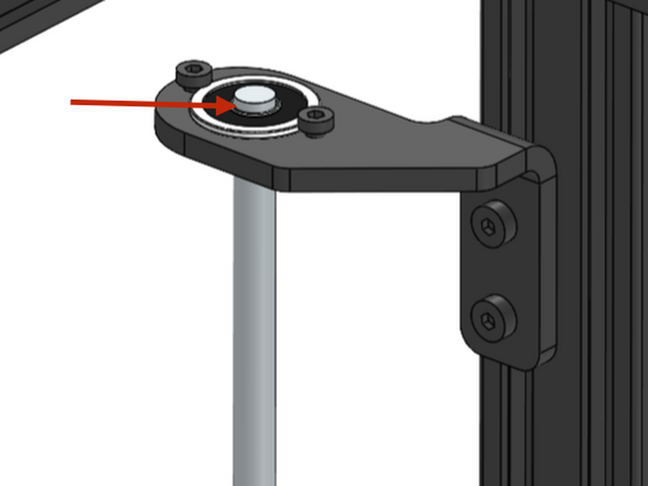
Slide the bearing over the lead screw, leaving just the top chamfer of the lead screw visible above the bearing.
I found leaving 5mm of the lead screw protruding above the bracket prevented me from later doing the Eddy Probe Homing scan -- the grub screws in the nut would bang into the bottom of the bracket. I needed to raise the bracket so that only the top chamfer of the screw protruded. I also had to replace the supplied grub screws with shorter grub screws, so that when properly tightened, the top of the grub screw did not extend past the top of the nut.
I did exactly the same thing - found out the same way. I'd had to add shims behind the lead screw nuts to get them smooth, now I don't need them, and the camera fits. Duh.
Phil Salkie - Open Reply
I ended up misinterpreting the images and installed these inverted as they wouldn't fit, it was only later when I was fitting the camera, that I realised these brackets are fitted to the insides of the left and right frames, and I'd fitted them to the inside of the front and rear frames. :doh
mike crane - Open Reply
-
-
-
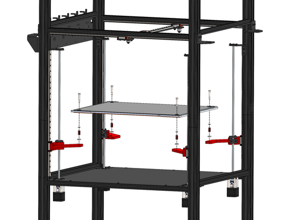
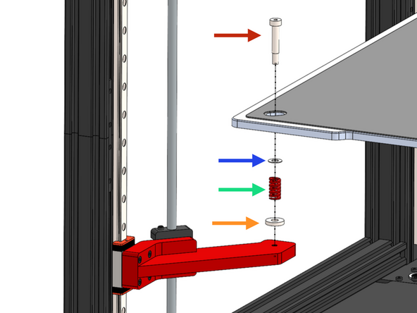
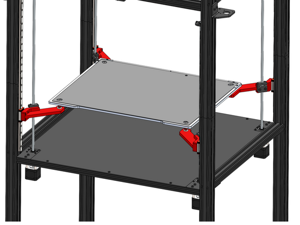
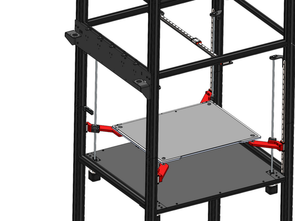
Install the print platform as shown. Ensure the cables come out of the left side of the platform.
-
M5 Shoulder Bolt
-
Shim
-
We’ve identified that the shim may have been left out of some kits. Please don’t worry — this part is not critical to operation and can be safely omitted. If you prefer, a standard M6 washer can be used as a substitute.
-
Bed Spring
-
Spacer
Appears the shim was possibly left out here. It's not critical and can be left out or an M6 washer can be used here if you have one.
Makertech 3D - Open Reply
-
-
-
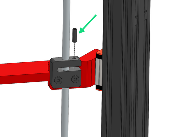
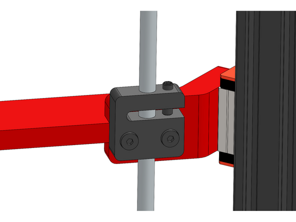
Insert into the four lead screw nuts the grub screw, turn until any play between the lead screw and nut has been removed.
-
Note, do not over tighten, the lead screw should still be able to rotate smoothly, over tightening can result in a z-motor stalling.
-
-
-
If you find that one of the lead screws does not rotate smoothly during inspection, please follow the steps below to correct the issue:
-
Carefully loosen (do not remove) the bearing brackets at the top and bottom of the lead screw.
-
Rotate the lead screw now - it should be smoother.
-
Re-tighten the brackets.
And make sure the brackets are the right way around - they fit perfectly upside-down, but they don't quite line up.
Phil Salkie - Open Reply
-
-
-
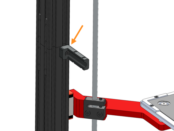
Secure the Z Cable Relief Bracket to the frame.
-
Z Cable Relief Bracket
-
M5 x 10mm Bolt
-
M5 T-nut
-
Secure the bracket just under the joint in the far left corner of the frame as shown.
-
-
-
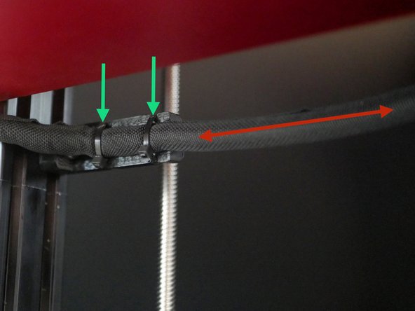
Cable tie the loom from the bed to the bracket.
-
Leave around 50cm of cable between where the loom exits the bed and is fixed to the bracket.
I figured out the probe cable - the "Probe" is a removable device that's there to calibrate nozzle positions between heads.
The cable is way too long, and arguably comes off the bed in the wrong spot - the connector's on the other side of the device.
I wound up tying up most of the excess cable to the mount point that's there, and the rest gets tucked into the loop when the device is not mounted to the bed.
Phil Salkie - Open Reply
What are we supposed to do with the probe cable that comes out of the center back of the bed? I see it goes into the electronics box, but I don't see how we're meant to route it? Why is it separate from the other wiring and coming out the back?
Phil Salkie - Open Reply
If you look at stage 5 step 4, it shows a good view of the wiring and which end needs the slack, I do believe the red arrow is on the wrong side of the bracket
Kevin McGraw - Open Reply
Image is correct, when I get out of millimeters and into centimeters I can start getting kind of lost sometimes
-
Cancel: I did not complete this guide.
9 other people completed this guide.

To me installing these bearings on the lead screws, and then securing them in place in Step 7 would make more sense.
Chaotic Muses - Open Reply
m4 x 8mm should be m4 x 6mm i believe ?
caleb punshon - Open Reply
Yes! Corrected.
Makertech 3D -