Difficulty
Moderate
Steps
10
Time Required
- Stage 04: Assembly 10 steps

In Progress
This guide is currently being written. Reload periodically to see the latest changes.

Private
This guide will not appear in search results and can only be viewed by team members!
Quiz
0
-
-
Use two M2.5 x 6mm bolts to fix the servo onto the backplate.
-
Make sure that the servo shaft is centrally aligned with the backplate.
-
-
-
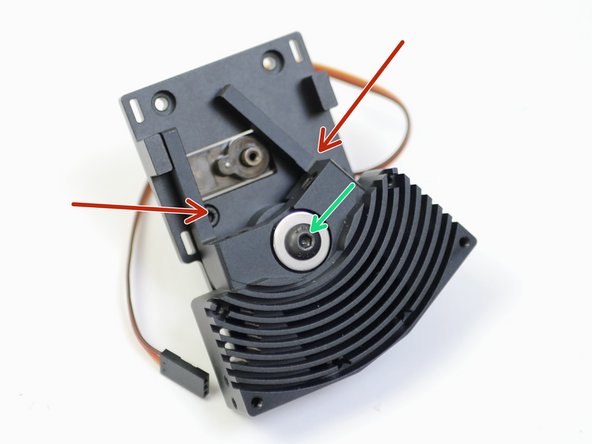
Insert an M5 x 20mm bolt with a needle bearing and shim.
-
M5 x 20mm Bolt
-
Needle Bearing
-
Shim
-
On the other side of the heatsink slide on another needle bearing.
-
-
-
Begin by preparing the backplate with two M3 x 30mm bolts as shown.
-
Drop an M5 nut into the back of the Backplate.
-
Fix the assembly together, making sure that there is no play in the switching motion.
-
The bolt should be tightened down enough to allow the heatsink to rock, but there shouldn't be any play along the axis of rotation or on the plane of contact.
-
-
-
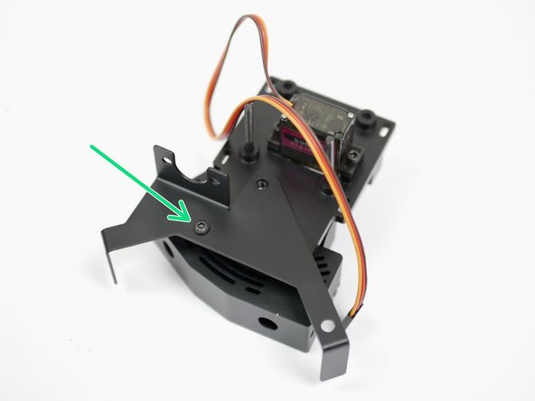
Fix the Probe and Fan mount onto the back of the backplate with an M3 x 6mm button head bolt.
-
-
-
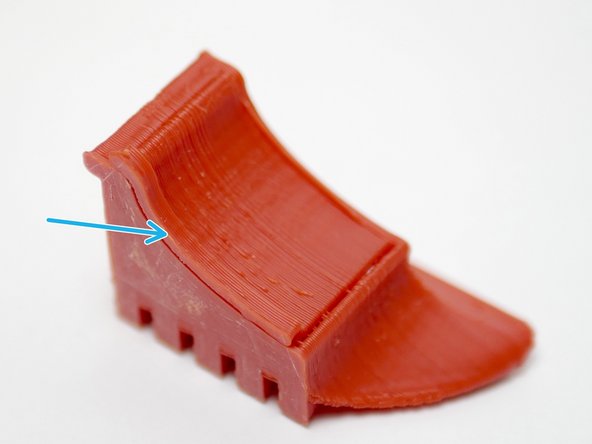
The part cooling fan shroud is a 3D-printed ABS part. Begin by removing the support with a pair of pliers by pulling on the tab.
-
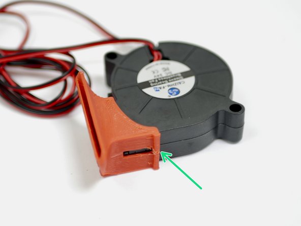
Fix the fan shroud onto the blower fan. The fan shroud is designed to snap in place.
-
-
-
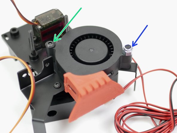
Fix onto the Backplate with a M4x22mm
-
Fix onto the Probe and Fan Mount with a M4 x 22mm bolt and M4 Nyloc nut.
-
-
-
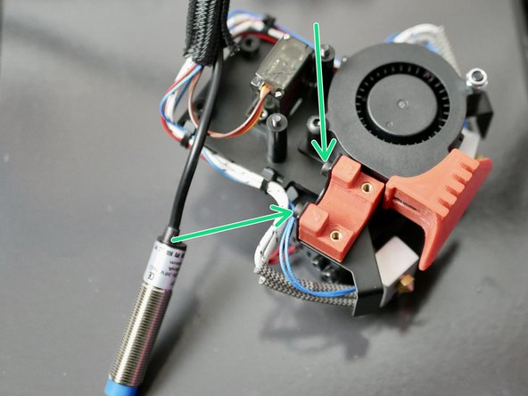
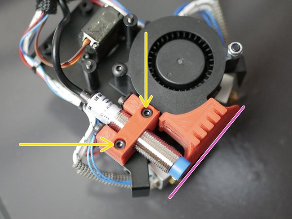
Fix the 3D printed probe mount to the metal mount like shown with two M3 x 6mm bolts.
-
Remove the nuts and washers from the probe and fix the probe to the mount, again with two M3 x 6mm bolts.
-
Adjust the probe so that the bottom of it is level with the bottom of the fan shroud, like shown.
-
Note, we've had to back track a little here, that's why more of the assembly is done in the images.
-
-
-
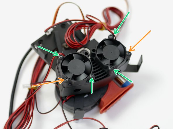
Fix the two 30mm fans onto the heatsink. Orientate the cables as shown.
-
M3 x 16mm bolt
-
M3 x 12mm bolt
-
-
-
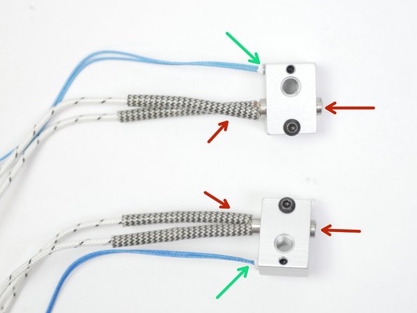
Take two heaters and fix them to the heater blocks.
-
Fix two thermistors to the blocks. We've shown two high temp. thermistors being installed here, but it is identical for the low temp thermistors too.
-
Make sure to match the orientation as shown in the photos. The two blocks should be mirrored.
-
-
-
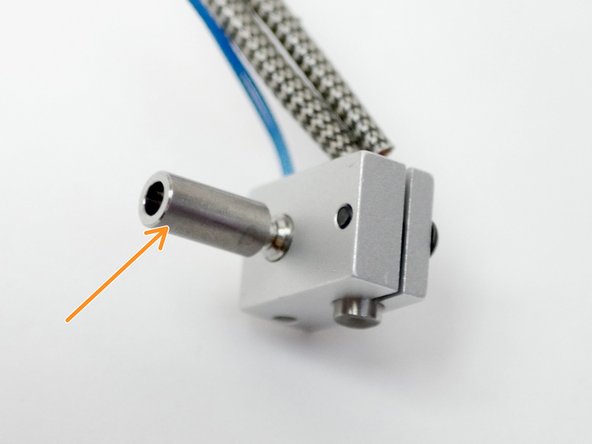
Fix onto both the heater blocks, the heatbreak.
-
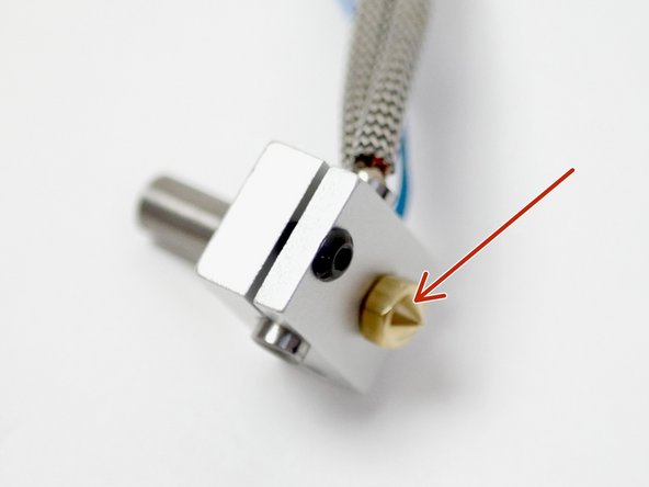
and the nozzle.
-
Make sure that the nozzle is tight against the heatbreak but leave a slight gap between the nozzle and heater block when tightening. The nozzle will need to be tightened again when hot.
-