
-
-
Take the filament sensor mount and fix a filament sensor onto it as shown.
-
M3 x 20mm
-
M3 Nyloc
-
-
-
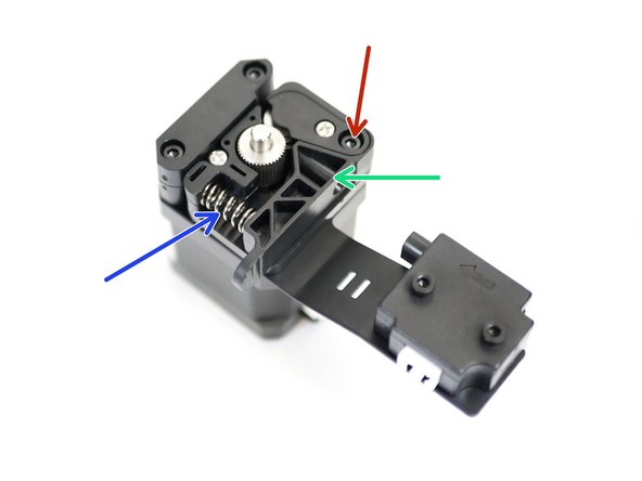
Extruder Spring
-
Drive Gear
-
Idler Arm
-
Back Plate
-
Coupling Mount
-
This part may have split, it contains a brass nut also. The coupling is attached later.
-
-
-
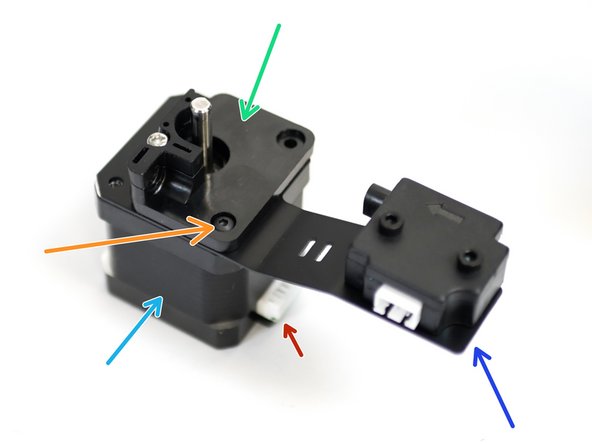
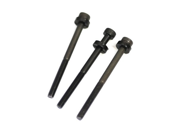
Take the following components and secure together with one M3 x 6mm bolt.
-
NEMA 17 Motor
-
Filament sensor mount assembly
-
Extruder Backplate
-
M3 x 6mm Bolt
-
Note the orientation of these components. In particular, the connector on the NEMA 17 motor.
-
-
-
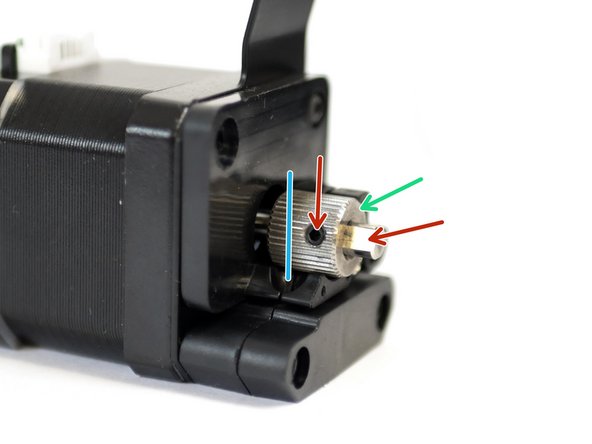
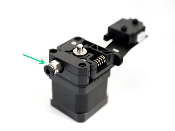
Slide the drive gear onto the motor's shaft.
-
Secure the grub screw against the flat of the shaft.
-
Align the gear so that the teeth line up with the path of the filament.
-
-
-
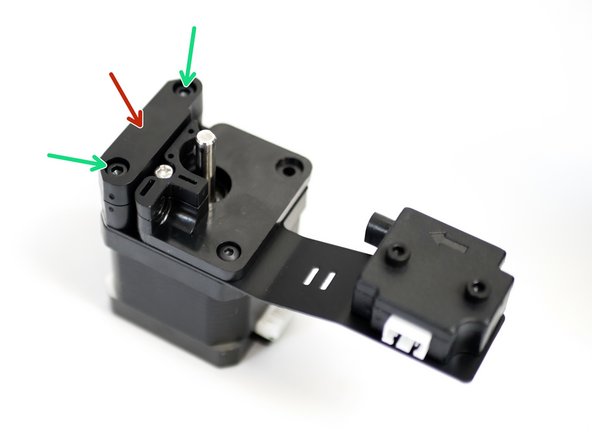
From the rear of the NEMA 17 motor remove three of the four bolts as shown.
-
-
-
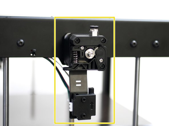
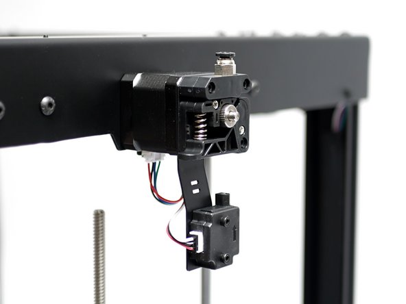
Slide the bolts in through the mounting holed on the Top Panel, from the inside.
-
Secure the Extruder assembly to the frame of the Proforge 3.
-
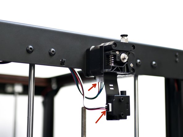
Finally, connect the motor and sensor cables.
-
-
-
Repeat the previous steps for the second extruder on the right side of the printer.
-


Cancel: I did not complete this guide.
3 other people completed this guide.
