
-
-
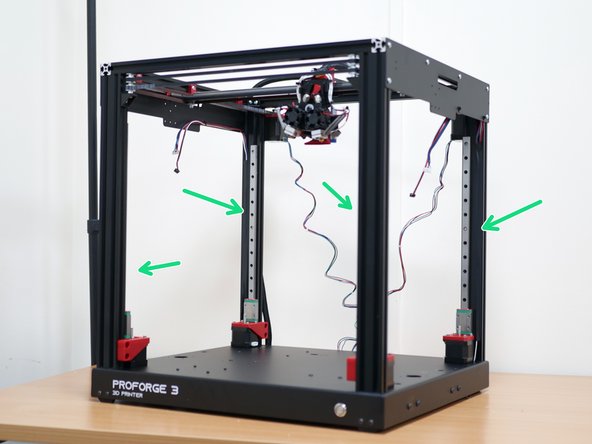
Remove the old motor cables from the frame.
-
Unplug them from the control board also and place them to one side.
-
If you have the Pi cam installed, also remove it and place it to one side.
-
-
-
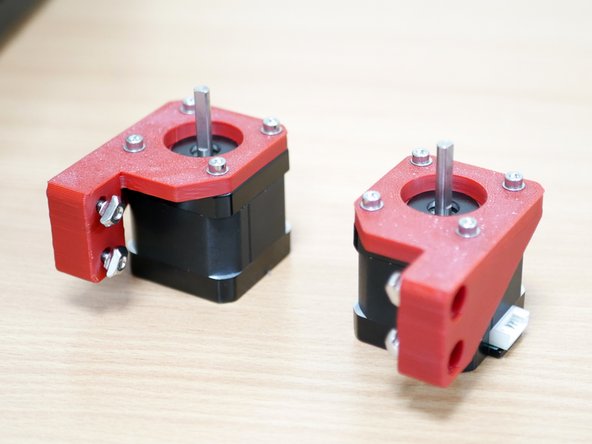
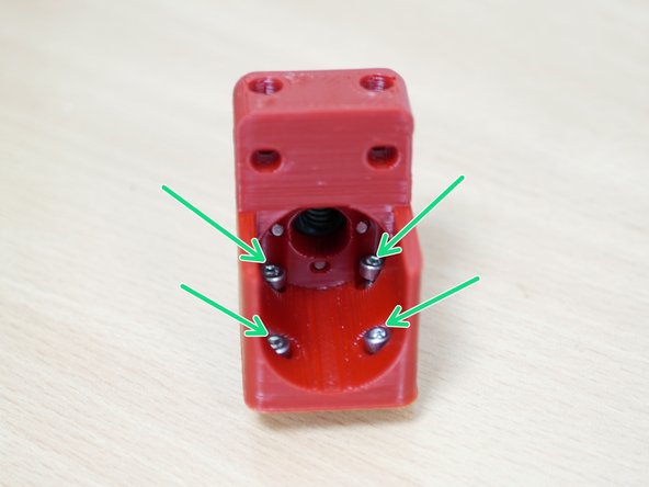
Remove the Z-axis motors from the base and fix them onto the 3D printed Z-motor mounts. Serial No. 42BYGH438.
-
Note, the mounts are mirrored. These two motors will be installed at the front of the base.
-
Orientate the motors as shown with the cable connectors facing away from the mounting holes.
-
M3 x 10mm Bolt
-
M3 Washer
-
M4 x 12mm Bolt
-
M4 T-Nut
-
-
-
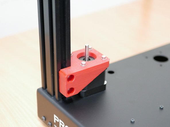
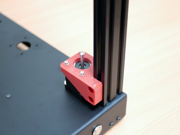
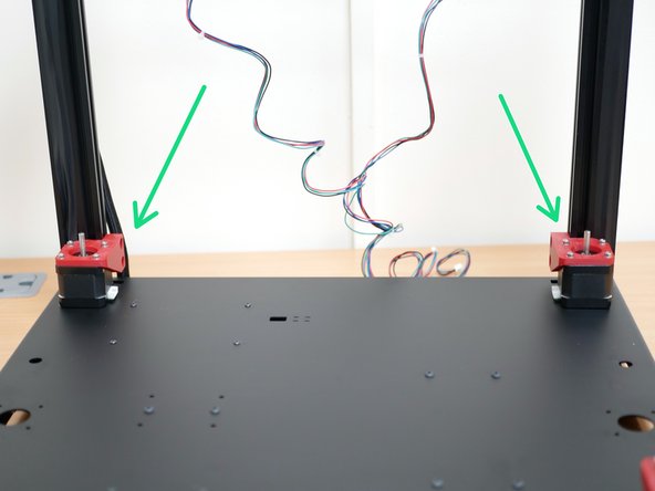
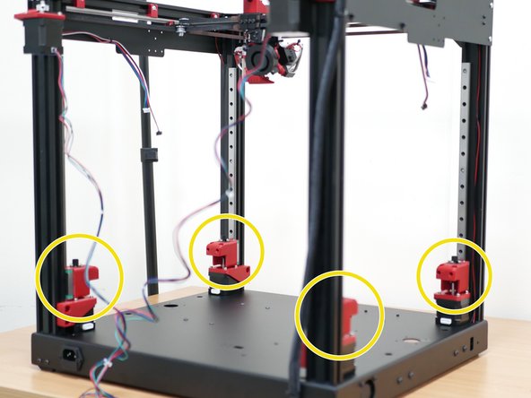
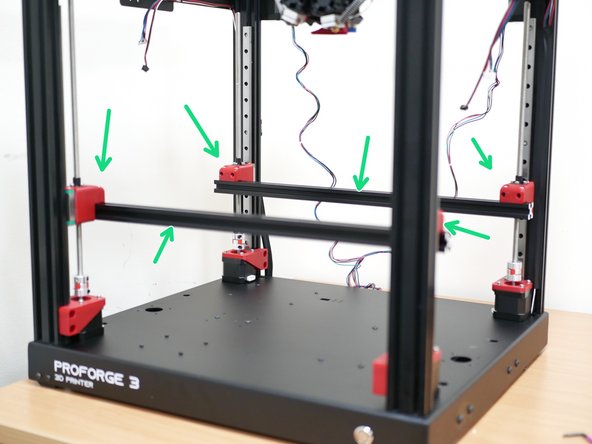
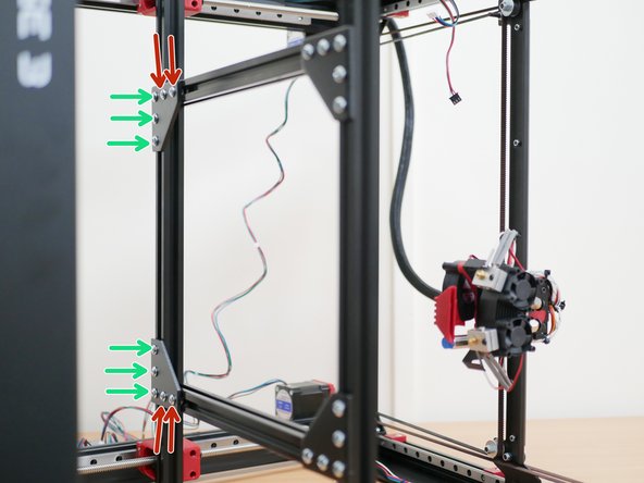
Secure those motor assemblies to the inside front of the frame as shown.
-
-
-
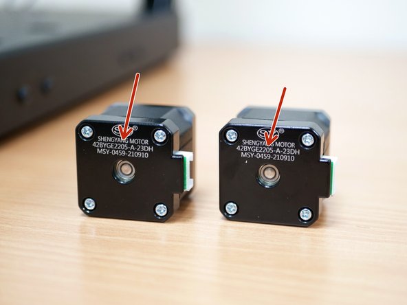
Take the two motors from the old Top Panel Assembly. The motor number should have a 205 in it.
-
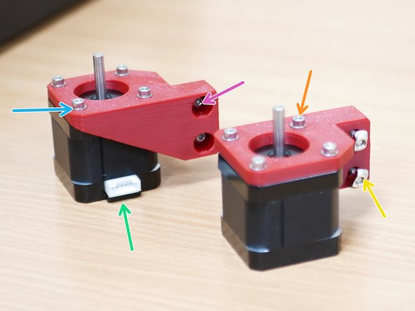
As before, the mounts are mirrored. These two motors will be installed at the rear of the base.
-
Orientate the motors as shown with the cable connectors facing the side of the mounting holes.
-
M3 x 10mm Bolt
-
M3 Washer
-
M4 x 12mm Bolt
-
M4 T-Nut
-
-
-
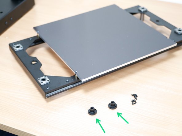
Take the old platform assembly and remove from it the lead screw nuts. The old bolts can be discarded.
-
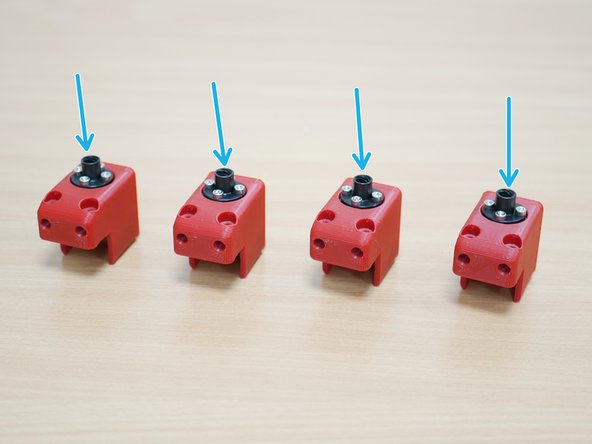
Fix these two lead screw nuts, with the two included in the upgrade kit, to the four 3d printed z-carriage parts.
-
M3 x 10mm Bolt
-
These bolts self tap into the 3d printed part, do not over tighten as it will strip the plastic.
-
-
-
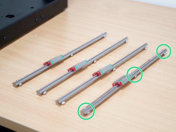
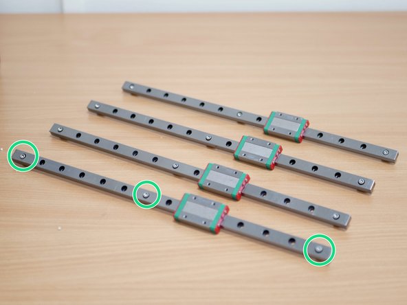
Prepare the linear rails as shown:
-
M3 x 10mm bolt
-
M3 T-Nut
-
Be careful that the carriages do not fall off the rails.
-
-
-
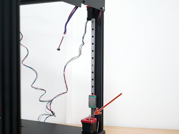
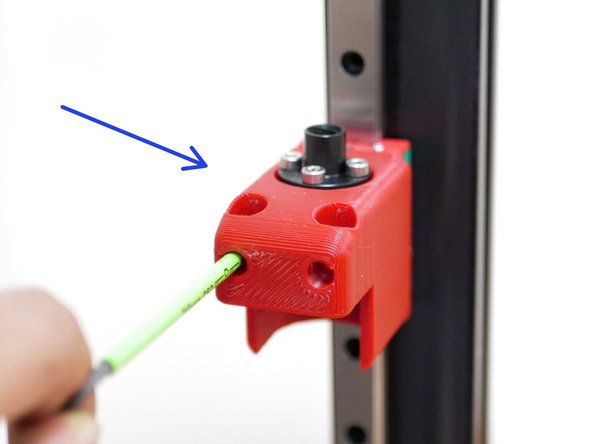
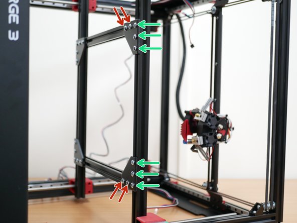
Fix the rails to the inside of the frame as shown.
-
When fixing the rail, press it down on the z-motor mount and then firmly tighten the bolts to the extrusion.
-
-
-
Drop four M3 x 10mm bolts into a Z-carriage as shown.
-
Mount the 3d printed carriage to the rail carriage as shown.
-
Repeat with he other three carriages.
-
-
-
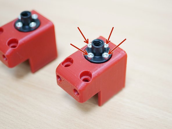
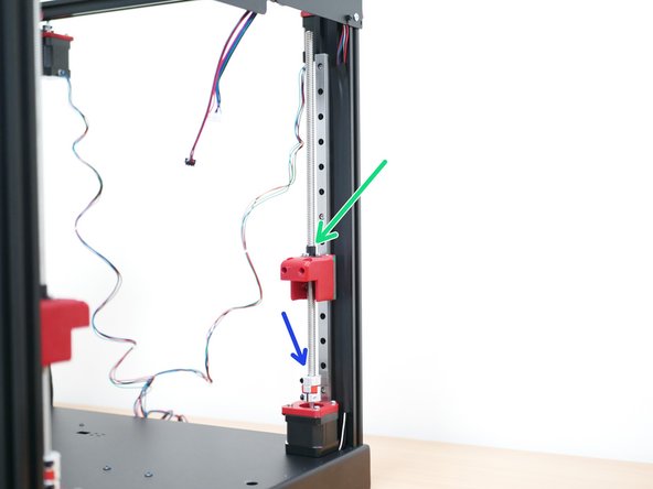
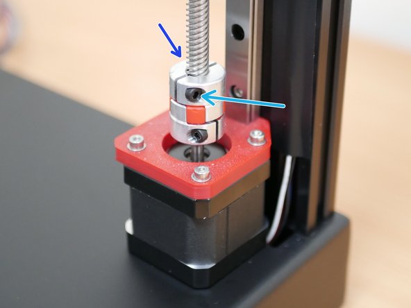
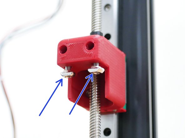
Thread the four lead screws (two form the upgrade and two form the original printer) through the top of the lead screw nut.
-
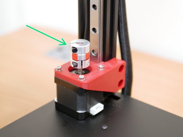
Feed it into the Plum Coupling.
-
Tighten this bolt to secure it in place.
-
-
-
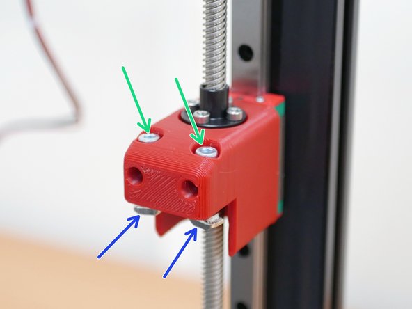
Drop into each of the Z-carriages two:
-
M4 x 20mm Bolt
-
M4 T-Nut
-
-
-
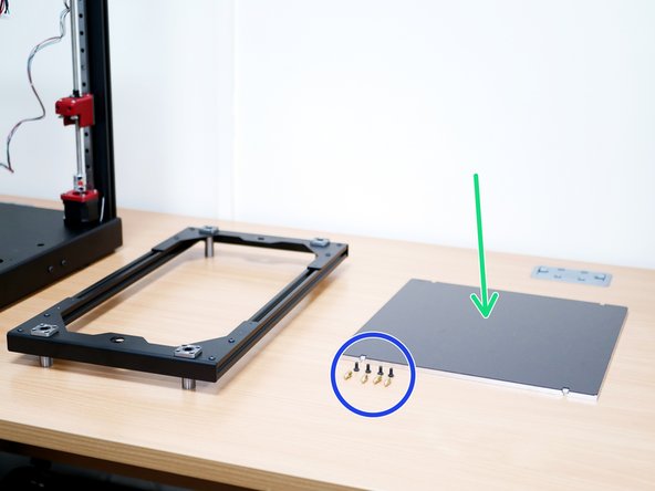
Remove the print platform from the platform frame.
-
Remove the standoffs and M4 bolts - keep these safe as they will be reused.
-
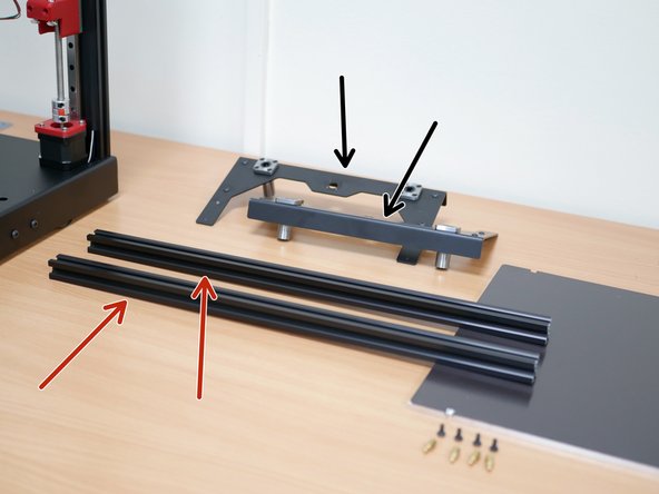
Remove the extrusions from the brackets.
-
These brackets can be discarded.
-
-
-
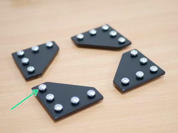
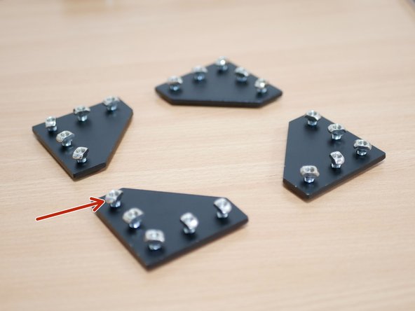
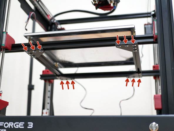
Prepare the four platform brackets as shown with:
-
M5 x 8mm bolts
-
M5 T-Nuts
-
-
-
Use the brackets to join together two shorter extrusions with the two longer ones.
-
The bolts that attach to the shorter extrusions - secure firmly.
-
The bolts that attach to the longer extrusions - secure loosely so that the shorter extrusions can still slide.
-
-
-
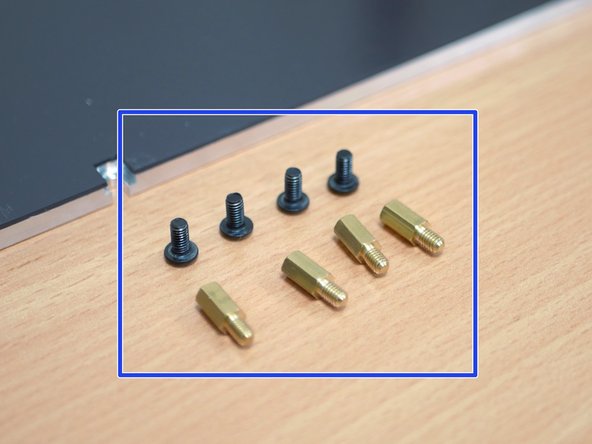
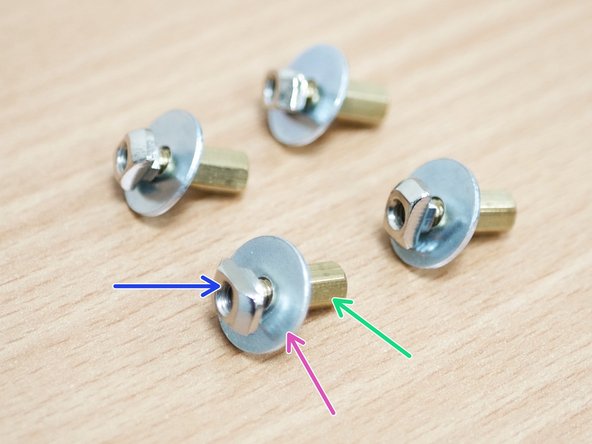
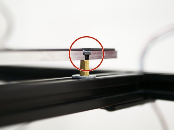
Use the brass stand offs from the old assembly and create four of these assemblies as shown
-
M4 Penny Washer
-
M4 T-Nut
-
-
-
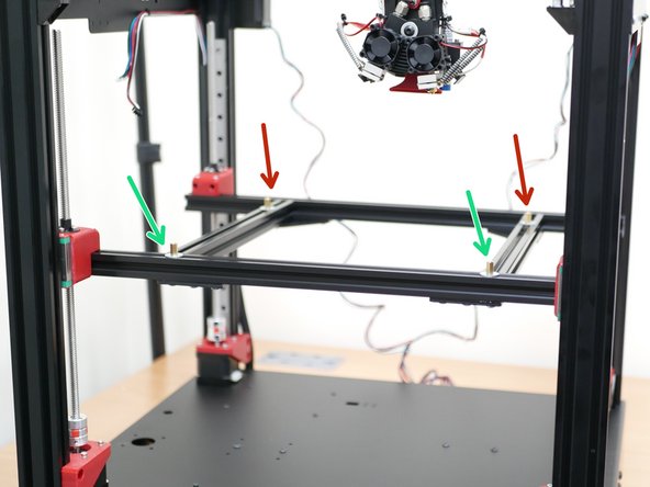
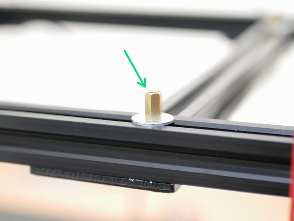
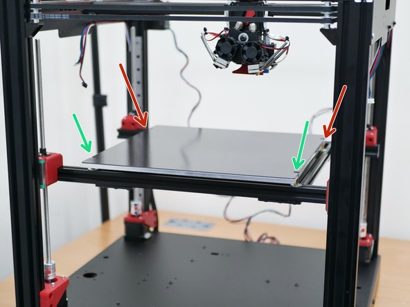
Loosely fix the platform mounts to the extrusions.
-
Position the front two on the longer front extrusion.
-
Position the other two on the sorter extrusions.
-
-
-
Mount the platform using the old M4 x 6mm bolts.
-
Firmly tighten the rear bolts and hence the mounts to the shorter extrusions,
-
Loosely fasten the front two bolts, so that the platform can still slide left and right.
-
-
-
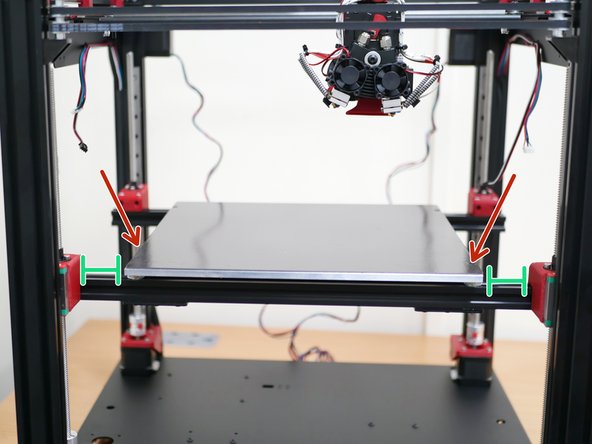
With the platform still able to slide left and right, adjust its position so that it lines up to the centre of the printer.
-
The distance between the edge of the platform and the 3d printed carriage should be approx. 47mm.
-
When happy it is approximately central, tighten down the remains loose bolts:
-
Front platform bolts
-
Bracket bolts
-


Cancel: I did not complete this guide.
4 other people completed this guide.
