-
-
Un-pack all of the rails and place them on a flat surface.
-
Each rail should have an orange stopper on the end to prevent the carriage from falling off.
-
Slide the carriage along the rail, make sure the movement is smooth and that there is no play. Take this opportunity to lubricate the rails.
-
-
-
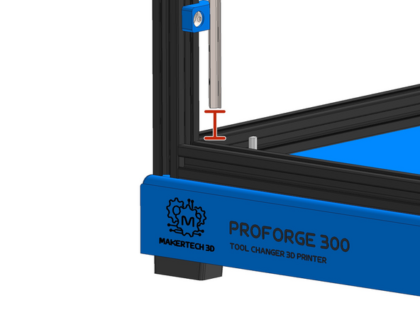
There are 4 350mm long rails.
-
For this platform stage of the build we need to select the rails that have been cut with the mounting holes nearest to the edge.
-
The remaining 350mm rail is intended for the gantry, it has its mounting holes 15mm from the edge.
-
-
-
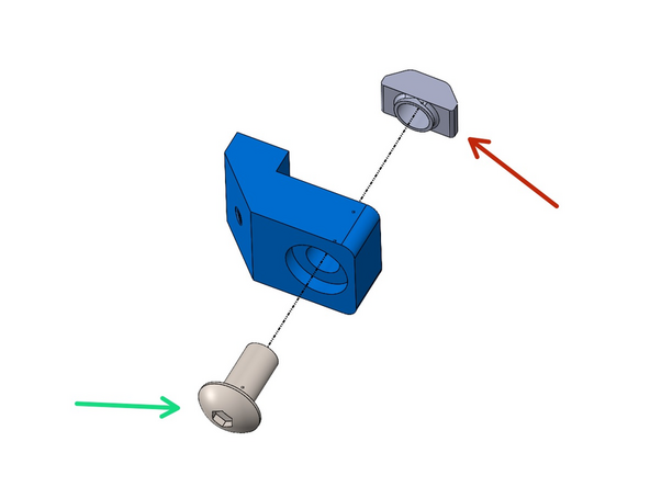
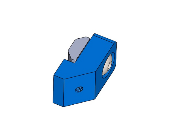
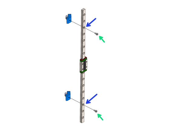
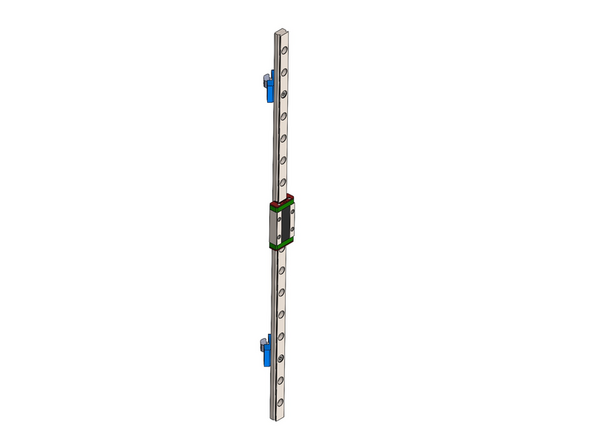
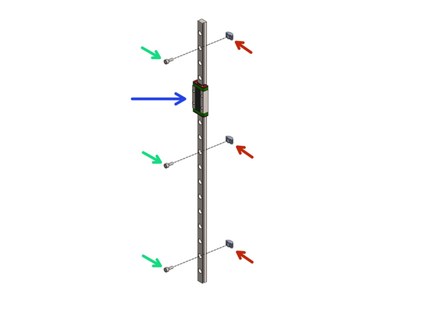
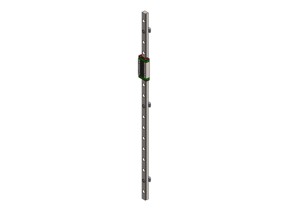
Fix the Z-Rail Mount assemblies from the previous steps onto two 350mm long MGN9 rails.
-
Fix onto two holes from the edge of the rails as shown.
-
M3 x 6mm Cap Head bolt
-
If you plan to install the enclosure take a look at the next step regarding the position of one of the brackets.
-
-
-
If you are installing the enclosure adjust the position of this Rail Mount by moving it one hole up on the rail. This is to allow room for the enclosure door hinge.
-
New position
-
-
-
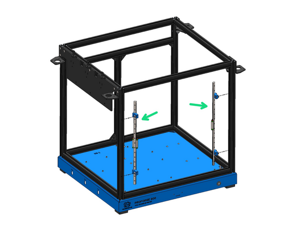
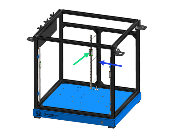
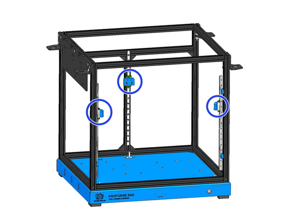
Mount the rail assemblies onto the inside of the frame as shown.
-
The bottom of the rail should sit ~20mm above the frames extrusion as shown.
-
-
-
Prepare the third Z-Rail as shown:
-
350mm MGN9H Rail
-
M3 x 8mm Cap Head Bolt
-
M3 T-Nut
-
-
-
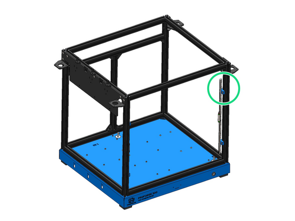
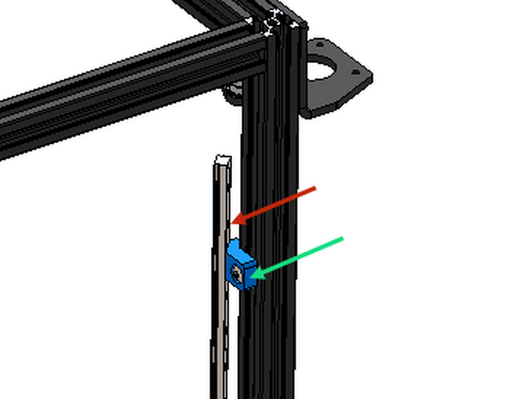
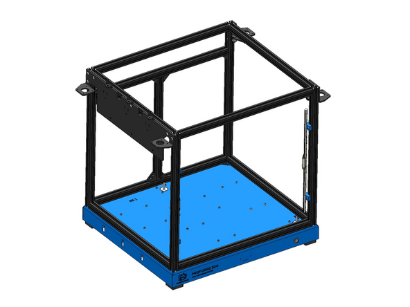
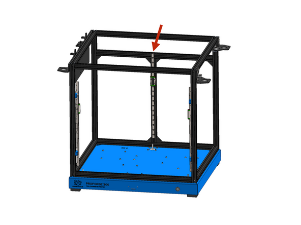
Mount the Z-Rail to the rear of the frame as shown.
-
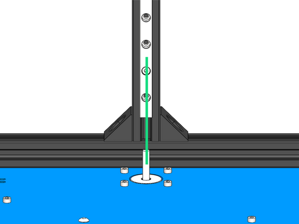
The rail should self align with the groove in the extrusion.
-
The top of the rail should sit flush with the top of the extrusion.
-
The vertical extrusion will need to be adjusted forwards slightly as the rail sits inside the groove.
-
-
-
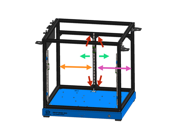
Adjust the rear extrusions position so that it lines up with the motor shaft.
-
Loosen these bolts to be able to slide the extrusion.
-
Exact distances:
-
219.5mm
-
230.5mm
-
No need be 100% precise - the Oldham coupling is built to handle misalignment.
-
-
-
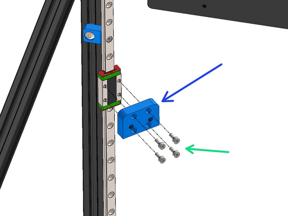
Fix the 3 CNC'd Z-Carriages onto the Rail carriages.
-
CNC'd Z-Carriage
-
M3 x 8mm Cap Head Bolt
-
-
-
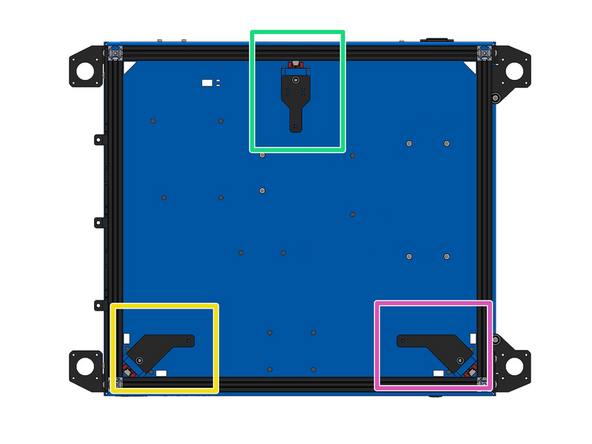
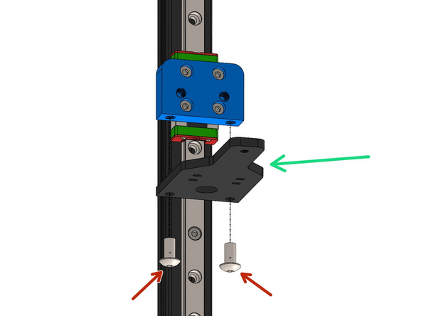
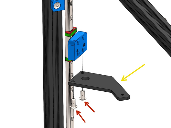
Fix to the underneath of the carriages from the previous step the three Z-Brackets.
-
M5 x 10mm Button Head Bolt
-
Rear Z-Bracket
-
Left Side Z-Bracket (shorter)
-
Right Side Z-Bracket
-
Note, the left side Z-Bracket has a shorter arm than the right side bracket.
-
-
-
Fix an anti-backlash nut onto each of the Z-Carriages as shown.
-
Anti-Backlash Nut - match the orientation as shown.
-
M5 x 16mm Cap Head Bolt
-
Place the grub screws to one side for now.
-
-
-
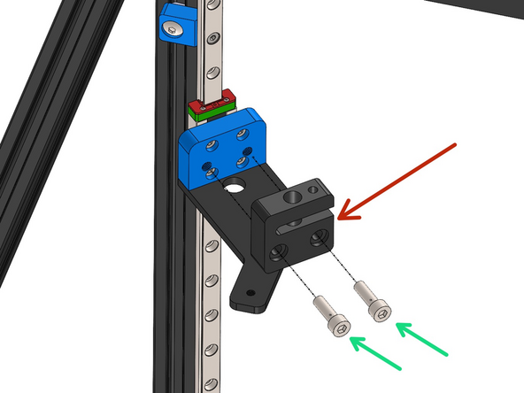
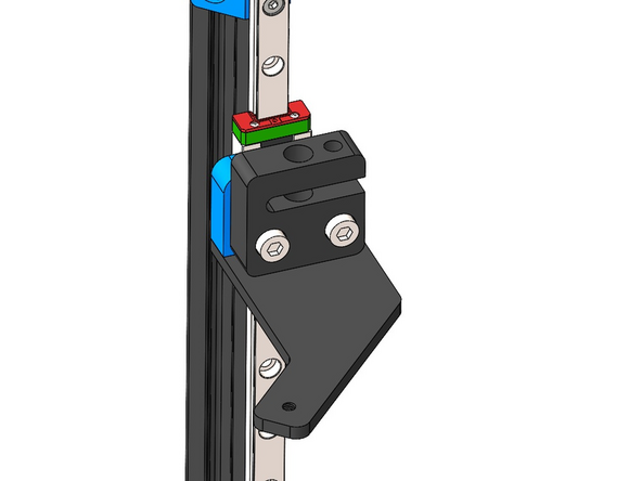
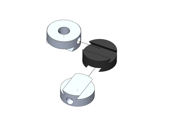
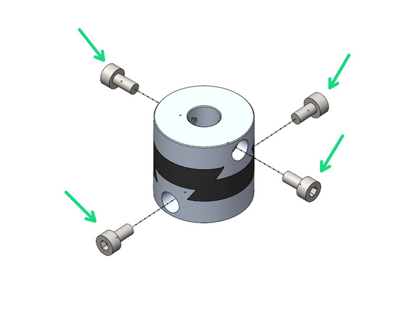
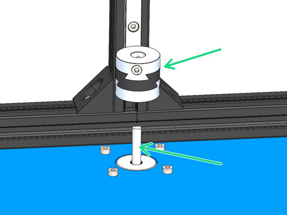
Assemble three Oldham Couplings as shown.
-
Loosely fasten: M3 x 6mm Cap Head Bolts
-
These couplings are designed to be a tight fit, however if you find the movement of yours to be too stiff we recommend either using some lubricant or carefully sanding down the inside faces.
-
-
-
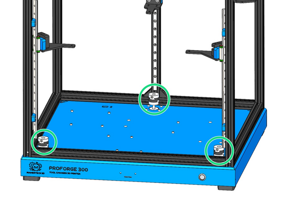
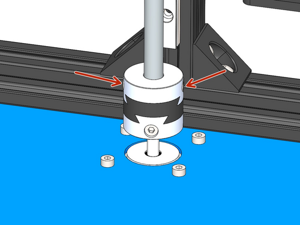
Fix the three Oldham Couplings onto the shafts of the Z-Motors as shown.
-
Tighten the bolts to hold in place. Make sure one of the bolts from the coupling is tightened against the flat of the motor shaft.
-
-
-
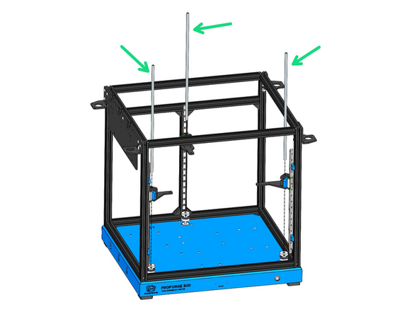
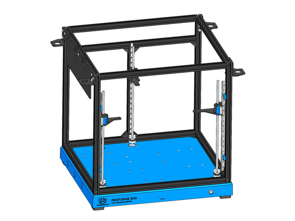
Thread the three lead screws through the anti-backlash nuts and down into the oldham couplings.
-
Tighten the bolts on the couplings to secure the lead screw in place.
-
-
-
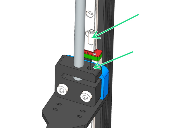
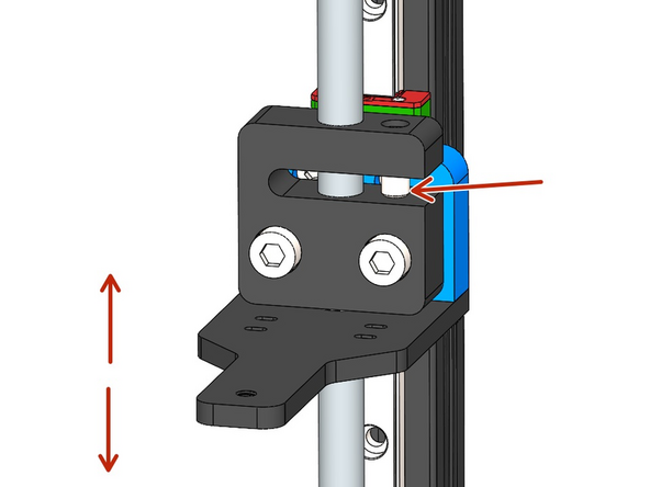
Move the carriage to its highest point, loosen the M5 bolts holding the nut and tighten again after checking the lead screw is straight.
-
Thread into the anti-backlash nut an M5 x 12mm grub screw.
-
Tighten the grub screw incrementally while testing the movement of the nut along the lead screw. The goal is to remove backlash without making the movement too stiff.
-
-
-
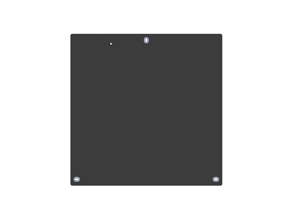
Before starting clean the platform surface with an alcohol wipe to ensure there is no dirt or grease on it. Ignore any coolant stains, this is normal.
-
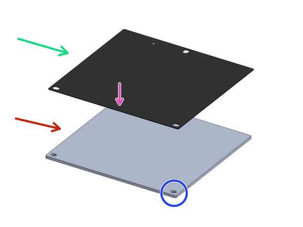
Stick over the aluminium platform the magnetic flex-plate sticker.
-
You may find this sticker, being magnetic, stuck onto the back of the black PEI flexplate.
-
Ensure it is stuck onto the side shown in the image where the mounting hole has a recess cut into it.
-
Peel away from the front edge the backing paper and line the sheet up with the edge of the platform. Press the sticker down carefully, preventing any air bubbles from forming. Continue pulling the backing paper away and pressing the sticker down onto the platform until the entire sheet is stuck down.
-
-
-
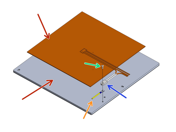
Flip the platform over and again use an alcohol wipe to make sure the surface is clean.
-
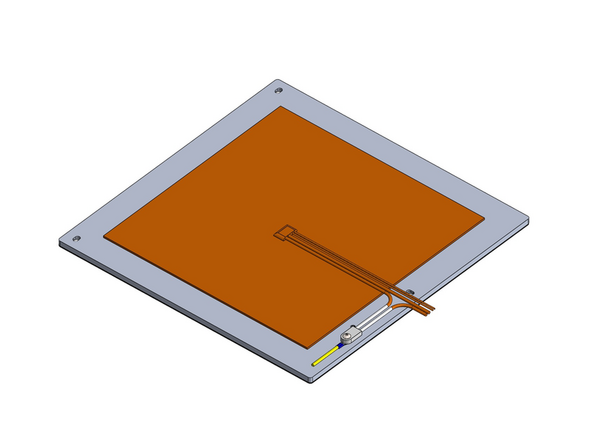
Peel the backing paper from the silicone heater and fix it to the centre of the platform as show.
-
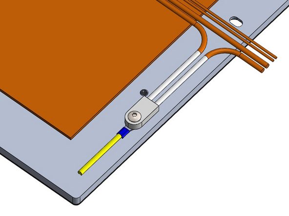
Orientate the cables as shown.
-
Secure in place:
-
M4 x 10mm Button Head Bolt
-
Thermal Fuse
-
If your heater is a Keenovo branded one the thermal fuse is built in. You will need to use a smaller M4x6mm bolt to fix the earth cable.
-
Earth Cable
-
-
-
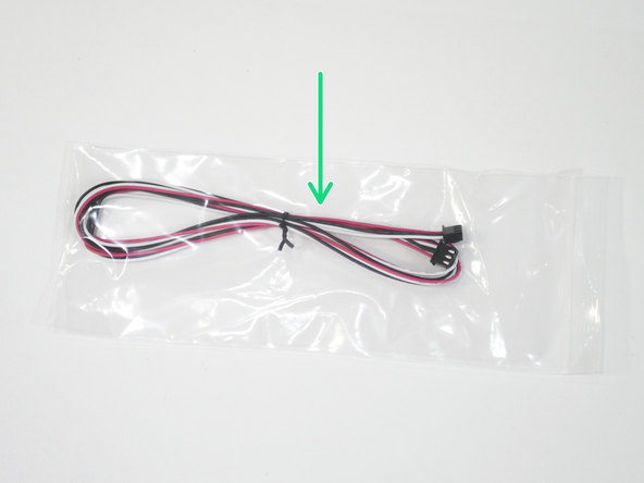
Add the calibration probe cable to the heater cables.
-
The calibration probe cable is a 1M long, 3 wire (red, white and black) cable that has a connector on either end.
-
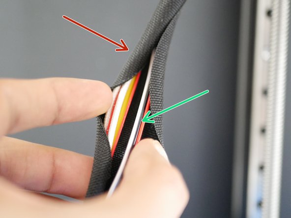
Take the braided cable sleeving and cut 50cm of it. Wrap all of the cables together in the sleeving.
-
-
-
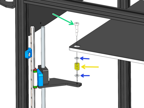
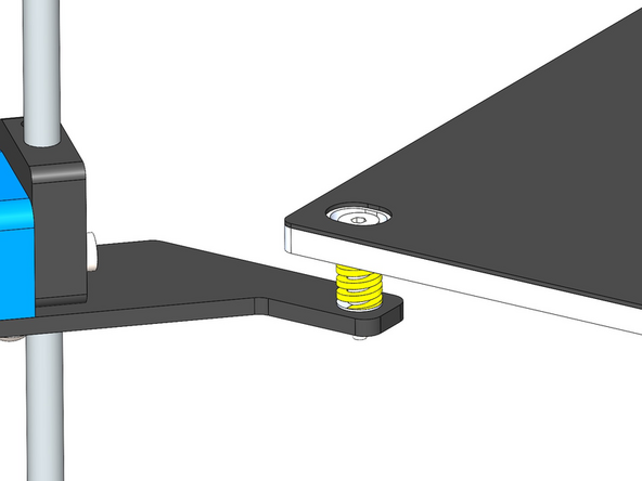
Mount the Platform Assembly to the Z-Brackets:
-
M4 D5 16mm Shoulder Bolt
-
M5 x 8 x 0.5mm Shim
-
Yellow Compression Spring
-
We recommend mounting the rear of the platform first and then the front.
-
-
-
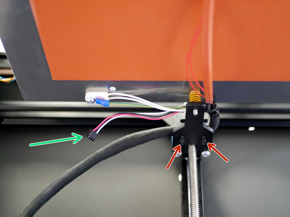
Use cable ties to fix the cables to the rear Z-Bracket as shown.
-
Ensure around 15cm of the probe cable is hanging out.
-
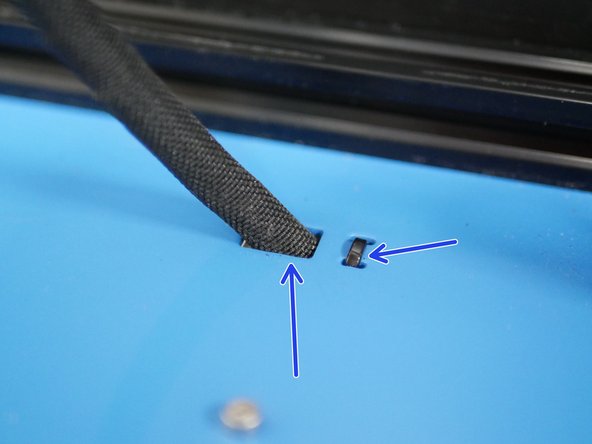
Feed the other end of the cables into the base and also secure with cable ties.
-
Secure the cable tie at the end of the braided sleeving.
-
-
-
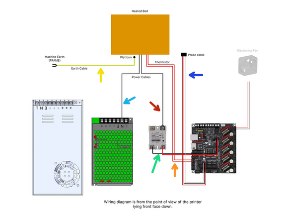
Wire the platform as according to the diagram.
-
Bed Signal Cable - 15cm
-
Probe cable
-
Bed Power Cables - polarity not important.
-
One cable to SSR Relay
-
One cable to Neutral line
-
Thermistor to control board.
-
Earth to cable to Earth line.
-
-
-
Before continuing it's important to double check your wiring. Make sure that the wires are plugged in the right way round, with positive going to positive and negative going to negative.
-
Incorrect wiring will cause irreversibly damage to the electronics.
-
Cancel: I did not complete this guide.
2 other people completed this guide.


