
-
-
If you have the MIC-6 heated bed upgrade, then please follow these steps for stage 5 of the build.
-
If you have the default 24V heated bed, then please continue with this version of stage 5.
-
-
-
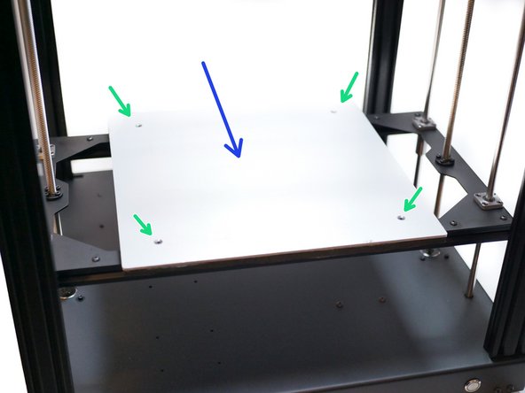
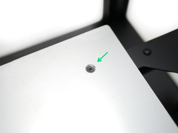
Take the four M3 brass stand-offs and secure them onto the platform assembly as shown.
-
-
-
Mount the heated bed onto the stand-offs that were installed in the previous step.
-
M3 x 6mm Button
-
Make sure that the cables are pointing to the rear of the printer.
-
Remove the protective film from the platform's surface.
-
-
-
With the heated bed mounted stick onto it's surface the magnetic sheet.
-
(Images to be added)
-
-
-
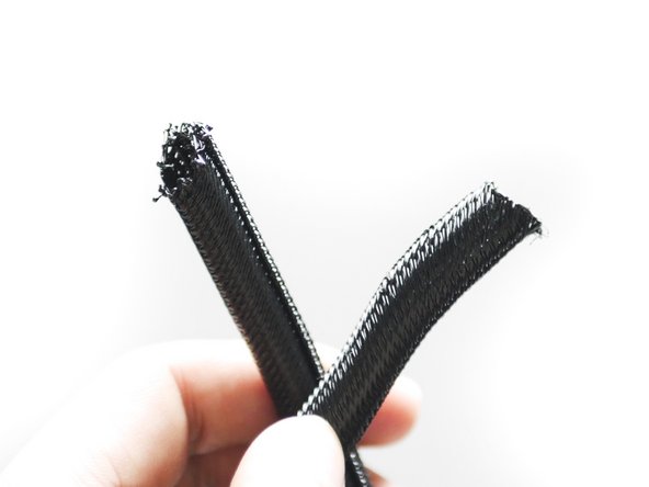
Cut approximately 60CM of the braided cable sleeving. Use a lighter to melt the ends to prevent fraying.
-
Slide the sleeving onto the heated bed cables.
-
-
-
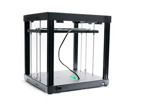
Raise the platform to the top.
-
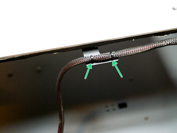
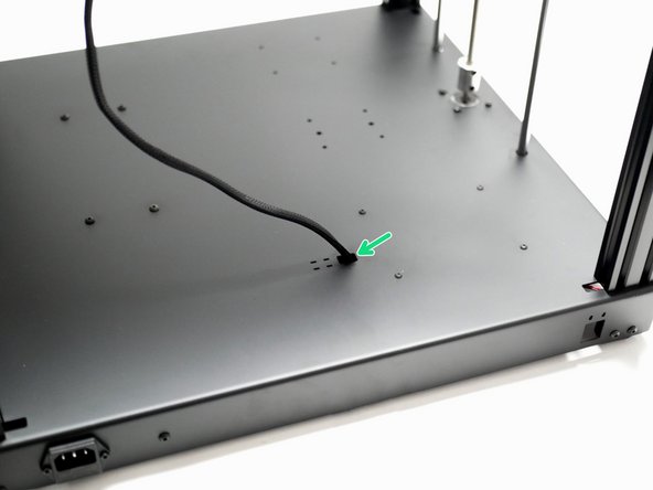
Feed the cables into the hole on the base and secure in place with two cable ties.
-
-
-
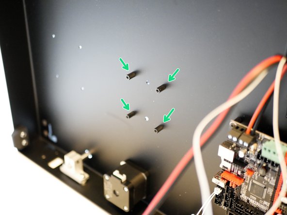
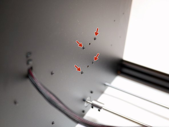
Secure four M3 x 10mm standoffs to the base like shown.
-
M3 x 10mm threaded spacer
-
M3 x 6mm button
-
-
-
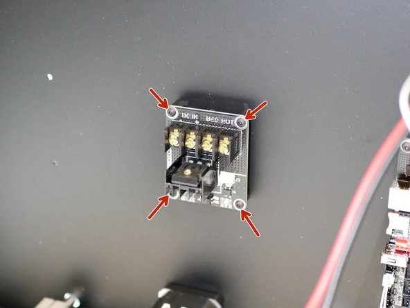
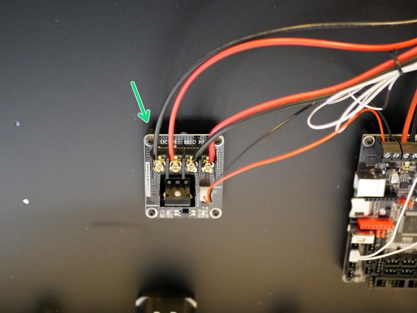
Secure the power cables from the heated bed onto the MOSFET as show.
-
Make sure that the cable orientation matches.
-
-
-
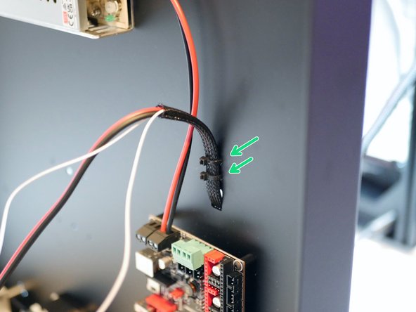
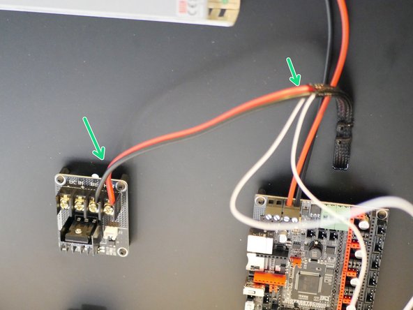
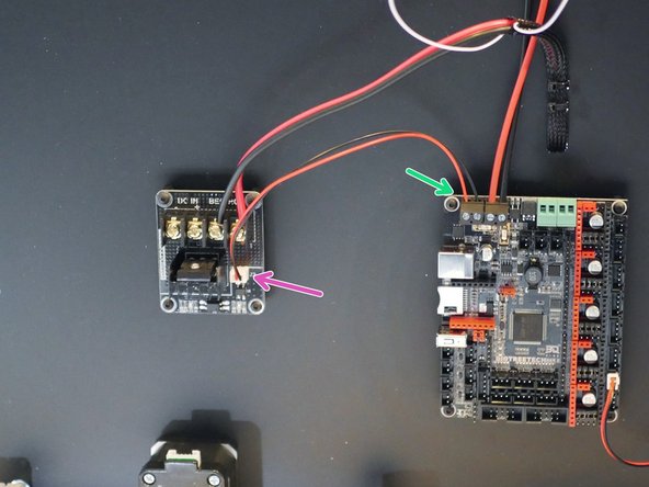
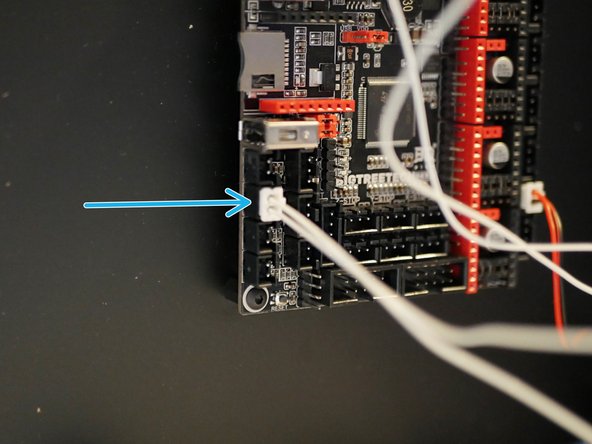
Connect the signal cable to the heated bed terminals on the control board.
-
Connect the other side to the MOSFET board.
-
-
-
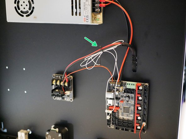
Connect the bed's thermistor to the board in the position shown.
-
Use a cable tie to wrap any loose cable.
-
-
-
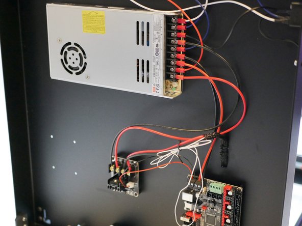
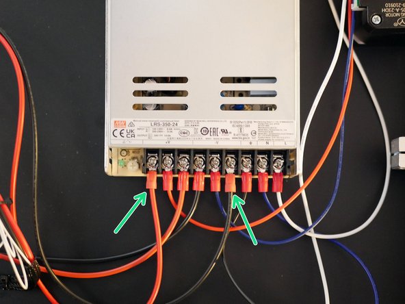
Connect power cables from the power supply to the MOSFET.
-
Red to positive.
-
Black to negative.
-


Cancel: I did not complete this guide.
One other person completed this guide.
