
Introduction
This guide assumes that you are some what familiar with editing your firmware. The guide focuses on the latest Marlin firmware.
-
-
Uncomment SWITCHING_NOZZLE
-
Set SWITCHING_NOZZLE_SERVO_ANGLES to 175 and 10. You may need to adjust this later on when fine-tuning your setup.
-
-
-
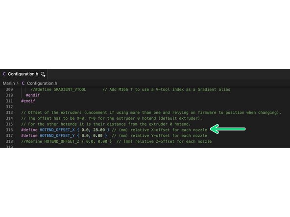
Set the nozzle offset for the switching hotends.
-
HOTEND_OFFSET_X { 0.0, 28.00 }
-
-
-
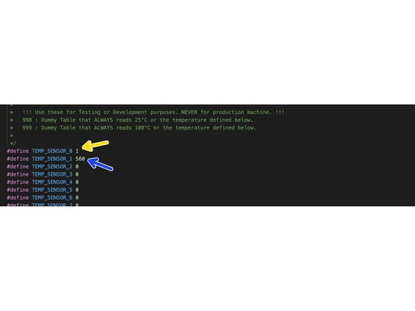
Set the thermistors (OLD):
-
Low temp (white cable) - set as 1
-
High temp (blue or white cable) - set as 66
-
Ignore 560 in the image.
-
NEW 2024 Thermistor:
-
As of 2024, both sides are high temp 300C sides with the same type of thermistor. If you received your kit in 2024 then set the thermistor value to 5
-
-
-
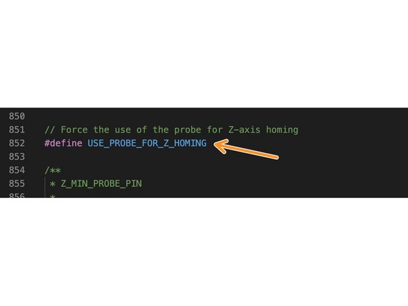
Set z-probe for homing.
-
Define nozzle/probe offset.
-
{39.5, 32, 0}
-
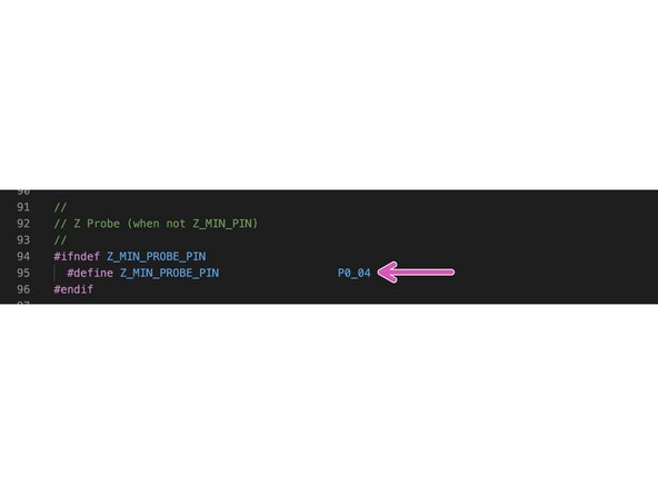
Probe Pins:
-
As mentioned before, in the wiring diagram, the probe's black cable needs to be connected to a digital signal pin on your control board. You can set this pin number by entering the following into either your configurtion.h file or directly into your boards pins.h file.
-
In lib/src/pins/...your control board
-
Here, the Z_MIN_PROBE_PIN is pointing to pin 4.
-
-
-
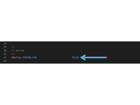
Similarly, in the wiring diagram, the servos orange cable needs to be connected to a digital signal pin on your control board. You can set this pin number by entering the following into either your configurtion.h file or directly into your boards pins.h file.
-
In lib/src/pins/...your control board
-
Here, the SERVO0_PIN is pointing to pin 5.
-
-
-
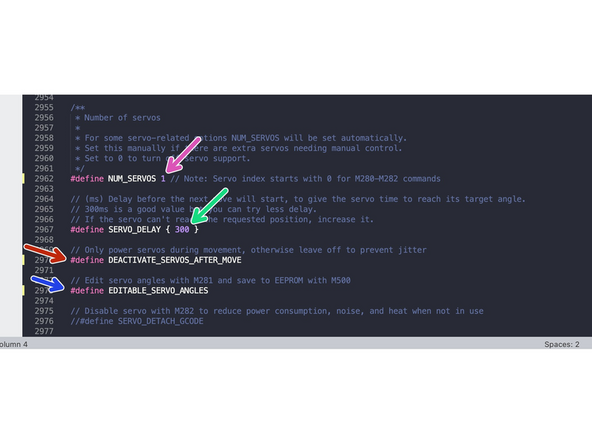
Set NUM_SERVOS 1
-
Set servo delay to 300.
-
Make sure that DEACTIVATE_SERVOS_AFTER_MOVE is activated (has the two dashes in front of it removed).
-
Also activate EDITABLE_SERVO_ANGLES
-


One Comment
Aiming for a solution of multicolour and support material. This could be achieved by building 2 'dual switch hot-ends' in the X-wagon. To avoid issues, I rather not position both 'active' hot-ends in a printing position, where the not printing hot-end is unpleasantly close to the printed layer.. Is it feasible to program the hot-end switch in such a way, that it will 'park' the inactive set in a half-way position? With my limited knowledge, the hardware should enable this. The logic is doable, but the translation to code is way beyond me. Does anyone have suggestions?
Tom Visser - Resolved on Release Reply