
Parts
No parts specified.
-
-
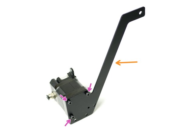
Fix the back plate to the motor face.
-
M3 x 6mm bolt
-
Match the orientation of the motors connector.
-
-
-
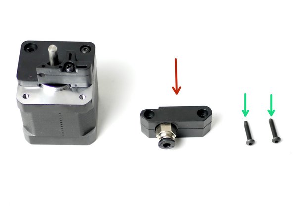
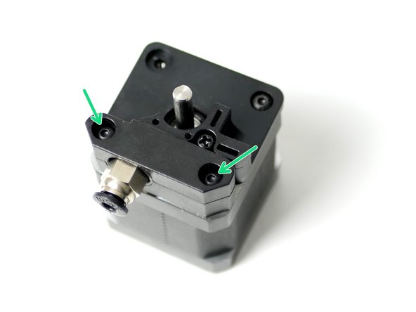
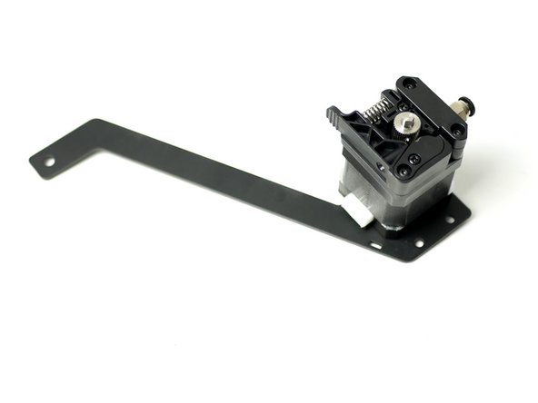
Fix the coupling mount to the face of the motor.
-
Coupling mount
-
M3 x 16mm bolt
-
-
-
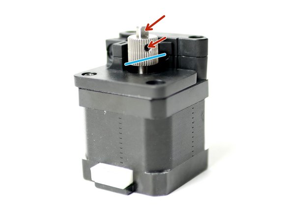
Align the drive gear so that it runs with the filaments path.
-
Filament path
-
Fix the Drive Gear to the shaft of the motor.
-
Tighten the set screw onto the flat of the shaft. Tighten firmly.
-
-
-
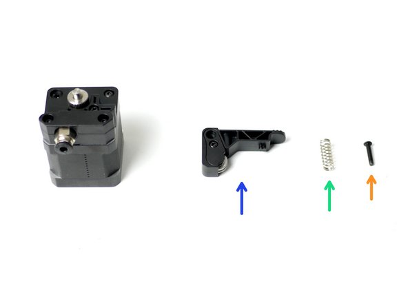
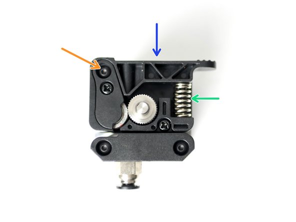
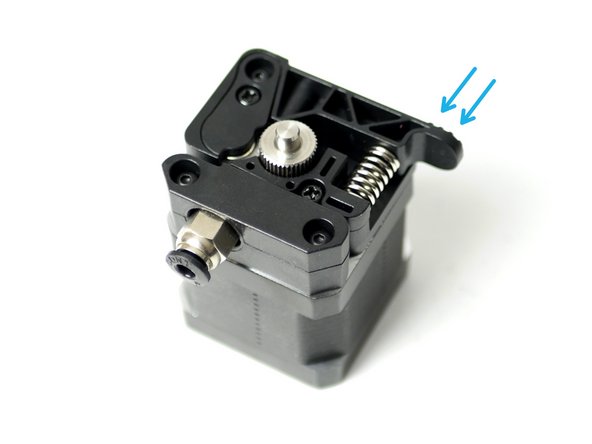
Take the Idler arm and attach it to the assembly.
-
Idler arm
-
Extruder Spring
-
M3 x 16mm bolt
-
Put the spring in place and hold the arm in position before dropping in the M3 x 16mm bolt.
-
Do not over tighten, the arm should still be able to swivel when pressure is applied.
-
-
-
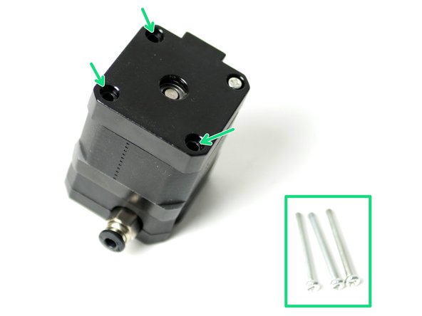
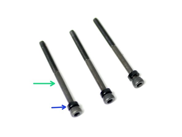
Take three M3 x 40mm bolts and slide onto each of them an M3x2mm spacer.
-
M3 x 40mm bolt
-
M3 x 2mm spacer
-
Fix these bolts onto the spool holder and fasten them into the back of the extruder motor, where the three bolts were removed in the previous step.
-
Spool Holder
-
M3 x 40mm bolt and spacer
-
Match the orientation of the spool holder shown.
-
-
-
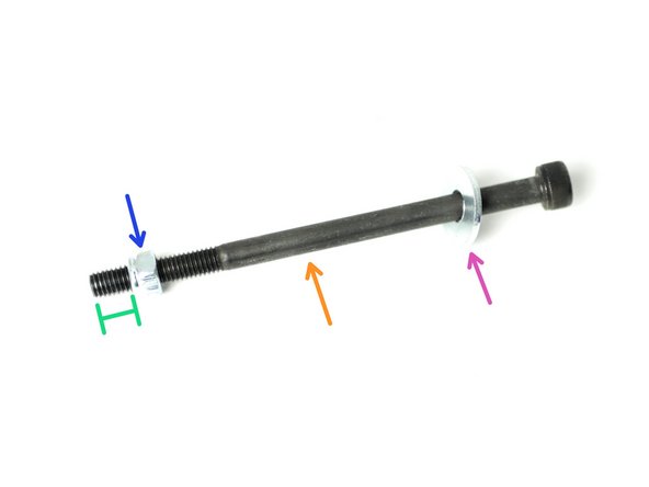
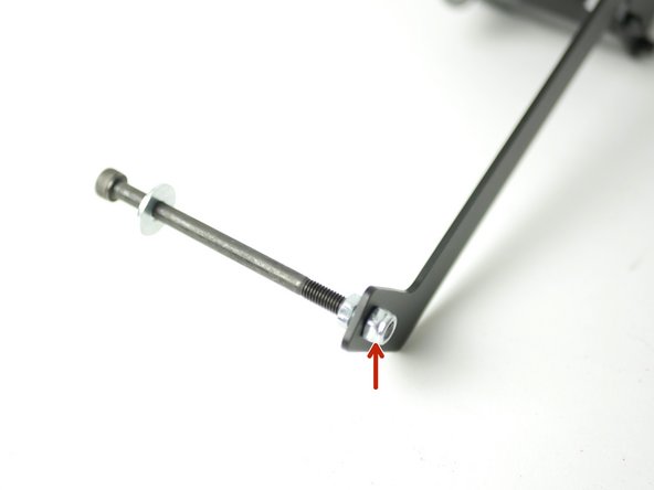
Create the spool holder arm:
-
M5 x 100mm bolt
-
M5 penny washer
-
M5 nyloc nut
-
Approx 1CM
-
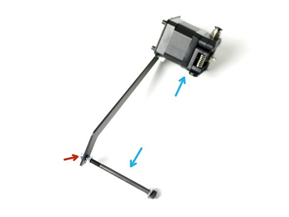
Fix the arm onto the spool holder bracket with another M5 nyloc nut.
-
Make sure that it is on the same side as the extruder.
-
-
-
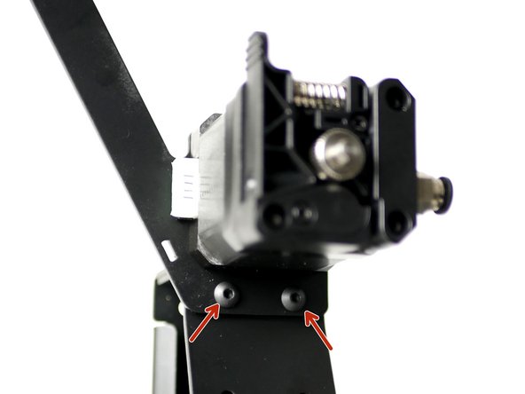
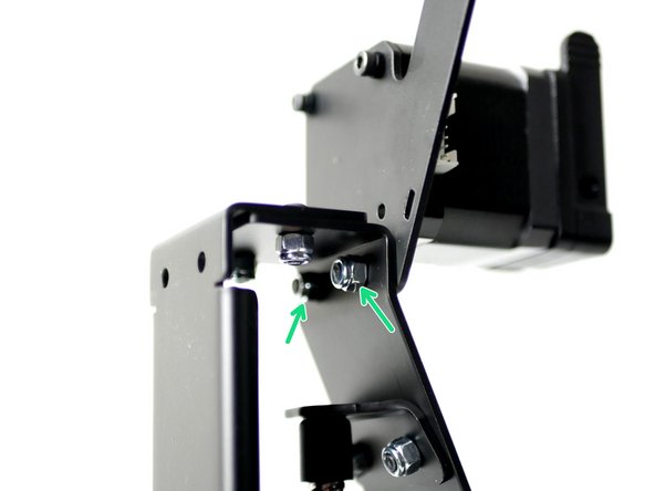
Mount the Extruder assembly onto the left the of the Z-pillar.
-
M4 x 10mm bolt
-
M4 nyloc nut
-
-
-
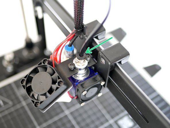
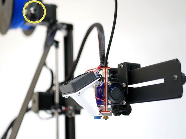
Insert one end of the PTFE tubing to the extruder.
-
Insert the other end into the Hotend.
-
Make sure that it is fed all the way to the bottom of the hotend, this should be approximately 6CM.
-
Double check, as running filament through the hotend with the PTFE tube not all the way down will clog the Hotend.
-
If your hotend does get clogged you will have to disassemble it to remove the clogged plastic from the hotend throat.
-


Cancel: I did not complete this guide.
18 other people completed this guide.

2 Comments
We’d recommend getting up and running with single extrusion first.
The dual extrusion guide is here: