
-
-
-
-
Unpack the camera by taking it out of its anti-static packaging.
-
Use the cable to connect the camera to your computer.
-
When connected you should get a feed from the camera to the software like this.
-
You may need to use the refresh button.
-
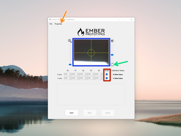
In properties make sure that Tool Changer is selected.
-
Make sure that both boxes for invert are checked.
-
-
-
Before starting make sure that your print heads are clear of any filament ooze.
-
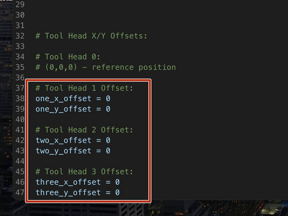
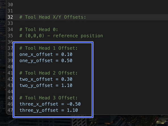
Make sure that your current X/Y offset values are all set to 0. Double check this in the variable.cfg file.
-
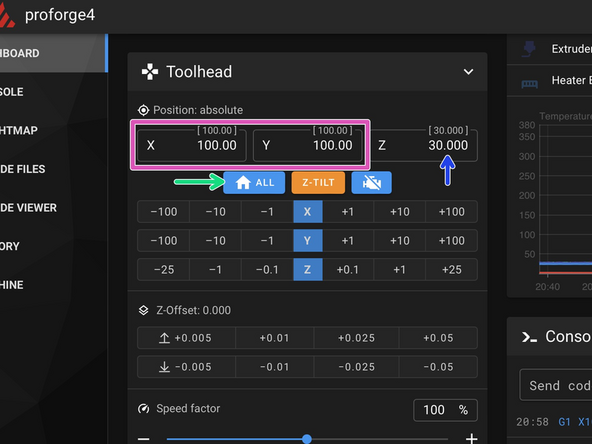
Home All.
-
Lower the bed to 30mm.
-
Select T0
-
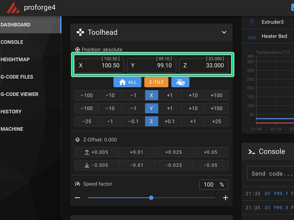
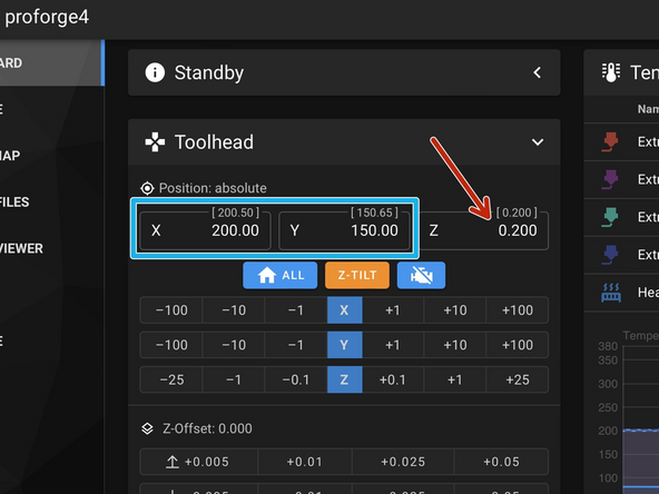
Move the print head to X/Y position (100, 100).
-
-
-
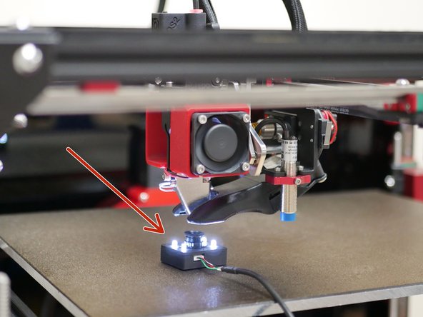
Place the camera module onto the platform - the module has a magnet underneath it which will stick to the platform.
-
Do not place the module onto the bed whilst the bed is hot - this can cause damage to the module.
-
Move the module to get it near to the centre of the print heads nozzle.
-
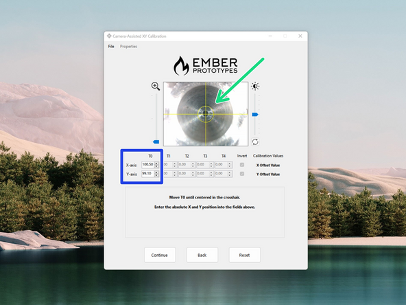
Next move the print head using the controls in Mainsail until the centre of the nozzle comes into focus and also lines up with the cross hairs of the camera feed.
-
When lined up hit start
-
Enter these X/Y values into the software under the T0 column as shown.
-
-
-
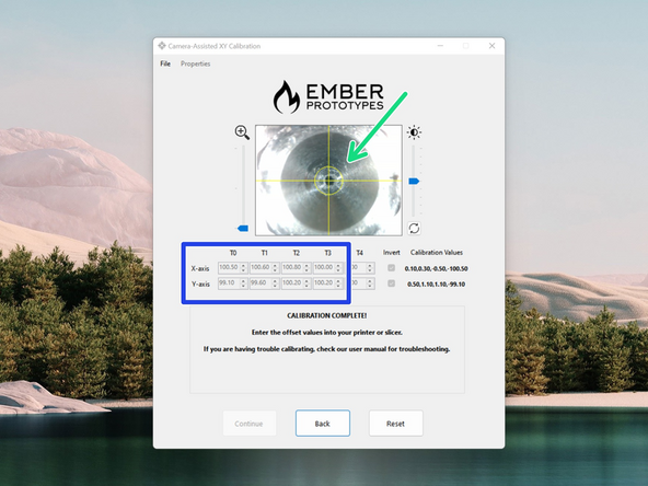
It's important when calibrating the remaining heads that the camera is not moved.
-
Use the macro controls in Mainsail to dock T0 and select T1.
-
Again use the controls in Mainsail to line the centre of the second print heads nozzle with the cross hairs on the software.
-
Don't forget to adjust the Z-value also, the bed is lowered by 1mm after each tool change.
-
Enter the X/Y co-ordinates into the software.
-
Repeat this for the remaining print heads.
-
-
-
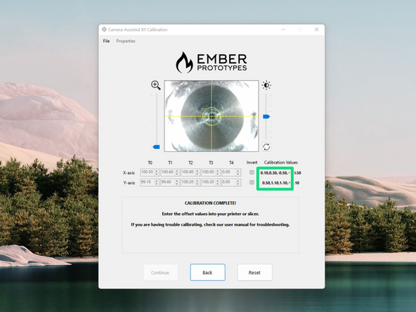
With all of the X/Y values entered in hit finish to get your offset values.
-
Enter these into the variables.cfg file.
-
-
-
With the offset for the first print head saved from this step in the previous stage continue with finding the offsets for the remaining print heads.
-
Set the bed to 100C.
-
The remaining Z-offsets are relative to the first print heads offset.
-
Select the print head, T1.
-
Move it to the centre of the build plate, co-ordinates (200, 150).
-
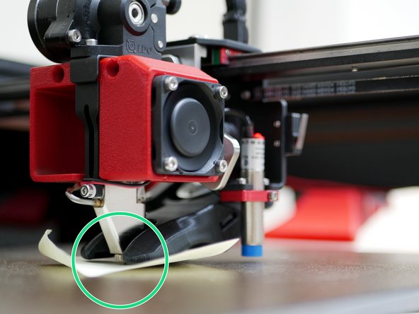
Place a piece of paper between the nozzle and the platform. Move the platform up to the nozzle and stop once it grips the paper.
-
Note the Z-position.
-
Repeat this for any remaining print heads you have installed.
-
-
-
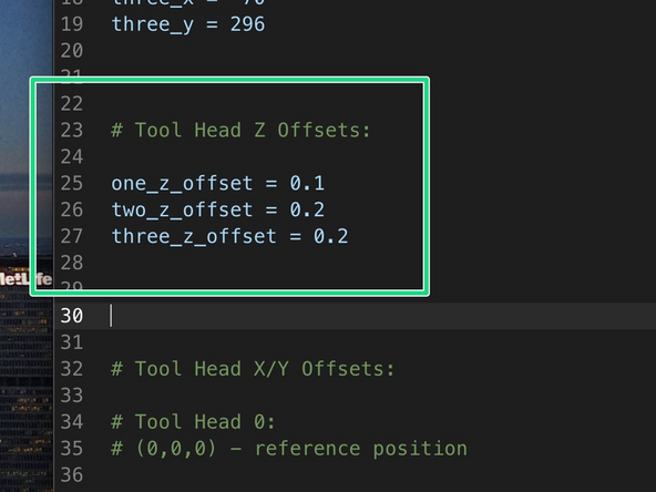
Enter the Z-offsets that you collected from the previous step into the variable.cfg file.
-
T1 = one_z_offset
-
T2 = two_z_offset
-
T3 = three_z_offset
-


Cancel: I did not complete this guide.
7 other people completed this guide.
