
-
-
The 3.5 Upgrade includes an 8GB SD card for use with Klipper.
-
The included card will work fine however for increased reliability (and longevity) we recommend upgrading this card. You will need at least 8GB:
-
-
-
-
-
Download the files needed for this stage here.
-
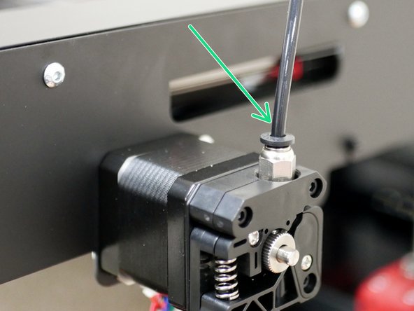
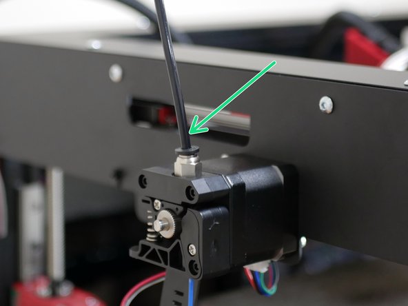
Copy only the firmware.bin file to the SD card that you should already have from the control board.
-
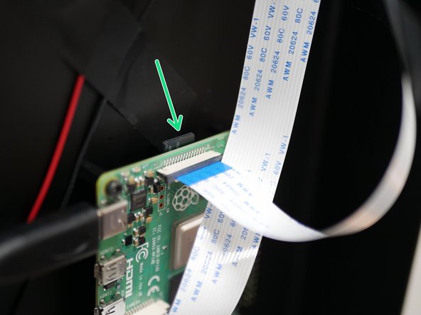
Insert the card back into the control board.
-
Ensure that you have a usb cable connected from the control board to your raspberry pi.
-
-
-
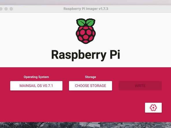
Follow the instruction here to create the bootable SD card image.
-
Choose the 32-bit option for the OS.
-
Follow only the first step, come back to this guide after you have flashed your SD card.
-
-
-
Insert the SD card into the Raspberry Pi and power up your printer.
-
Give the Pi a few minutes to boot up.
-
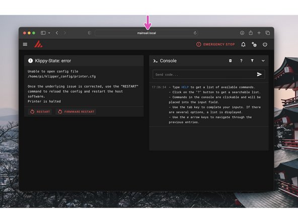
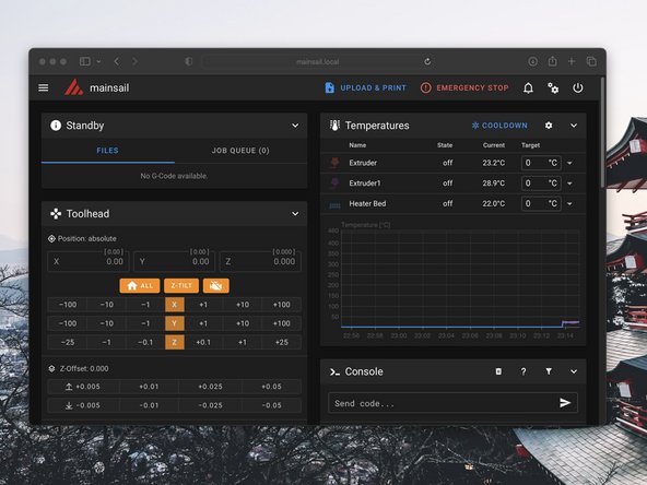
In your browser type mainsail.local to bring up the printers control panel.
-
Make sure that your device is connected to the same network as the printer. You should have set the network name and password in the previous step.
-
If everything is setup correctly you should be greeted with this screen. There are a few more steps to complete in order to set up Klipper.
-
-
-
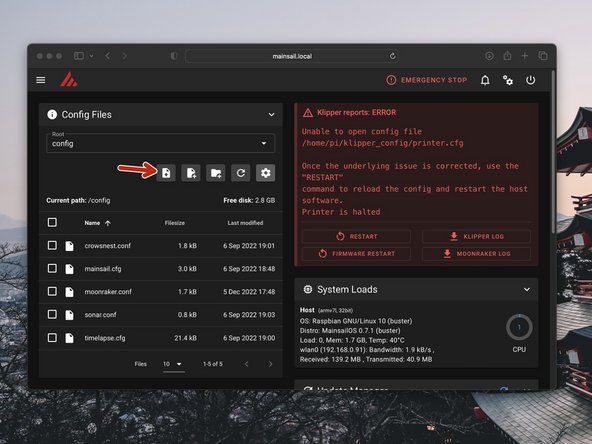
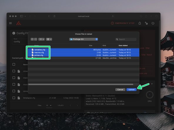
In the config files section, click on upload.
-
Find the three config files that you downloaded in step two and upload them.
-
-
-
In order for Klipper to communicate with your control board it needs what's called a USB id.
-
Each control board has a unique id. In order to find yours we need to SSH to the Raspberry Pi first.
-
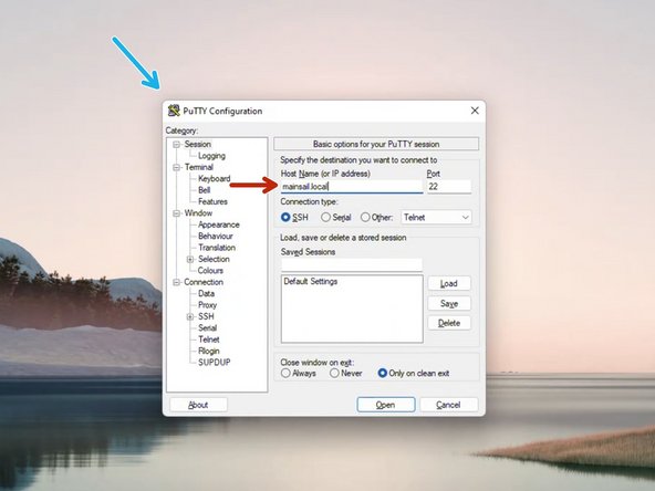
On windows you will need a software called Putty, download it here.
-
In putty type in mainsail.local and hit connect. Then click accept.
-
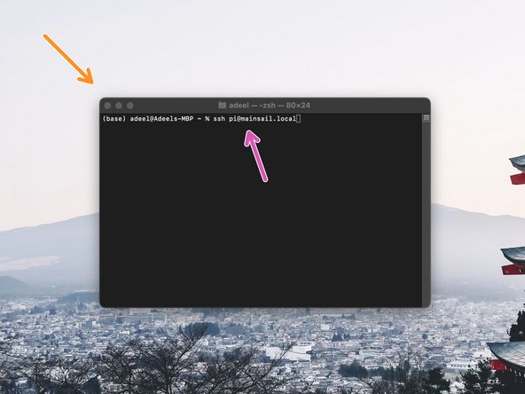
On MAC/Linux you can simply use the pre-installed terminal.
-
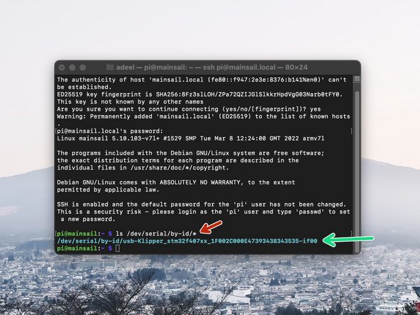
Just type in ssh pi@mainsail.local and hit enter.
-
-
-
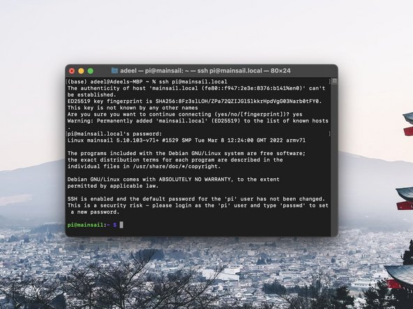
After connecting login with the username and password you had set when creating the pi image in step 3.
-
The default username should be pi.
-
The default password is raspberry.
-
When typing in the password you will not get any keystroke feedback from the terminal, just hit enter after typing it in on your keyboard.
-
-
-
Send the following to get the USB id:
-
ls /dev/serial/by-id/*
-
Copy the output to your clipboard.
-
Keep the terminal open and connected, we will use it again for the Touch Screen firmware install.
-
If you don't get an output in a similar to the one shown then troubleshoot with the following:
-
Whilst powered up, hit the reset button on the SKR control board. It is a small black button that can be found on the board near the mounting hole by the thermistor ports.
-
Change usb cable
-
-
-
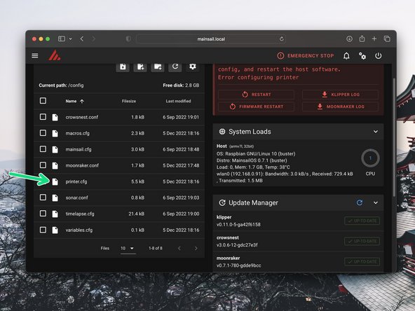
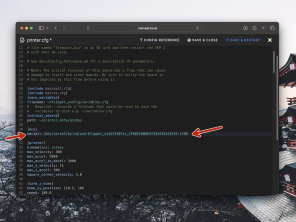
In mainsail open the printer.cfg file that you previously uploaded, by clicking on it.
-
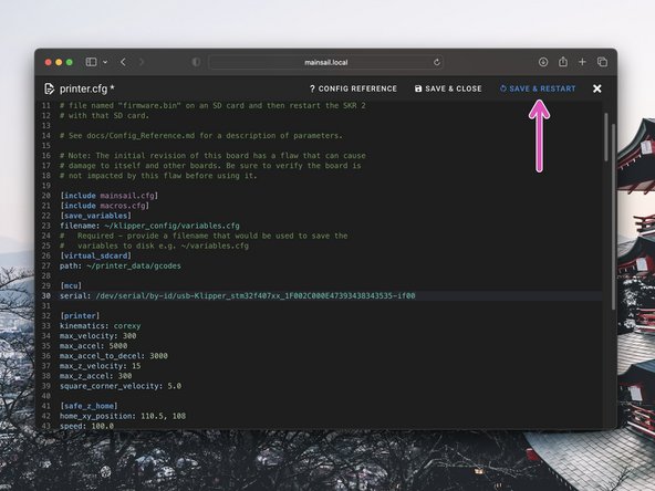
Paste the line that you previously copied here, after serial:
-
Click Save & Restart when done.
-
-
-
After restarting Klipper you should now have a connection with the printer.
-
-
-
Complete this step if you have the new Touch Screen display installed.
-
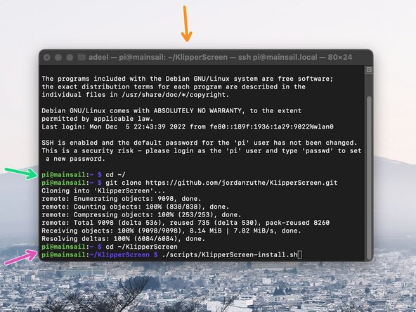
Head back to your Putty/terminal window and send the following:
-
cd ~/ git clone https://github.com/jordanruthe/KlipperScreen.git
-
Once downloaded send the following:
-
cd ~/KlipperScreen ./scripts/KlipperScreen-install.sh
-
Enter your password if prompted.
-
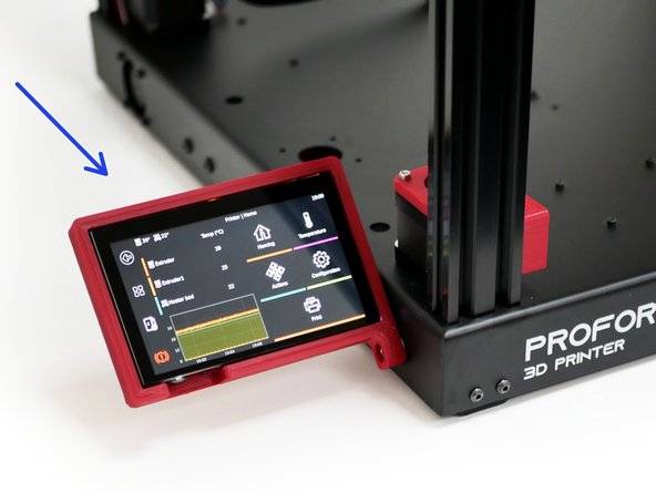
The installation can take several minutes.
-
When finished your screen should become active.
-
-
-
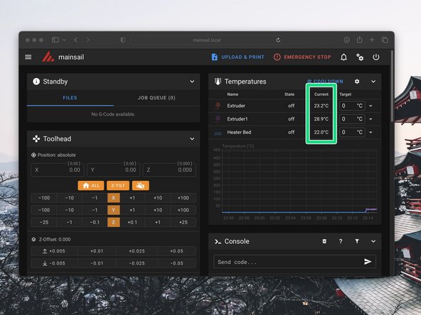
In the mainsail dashboard check that you are receiving the correct temperature readings - i.e. room temperature
-
-
-
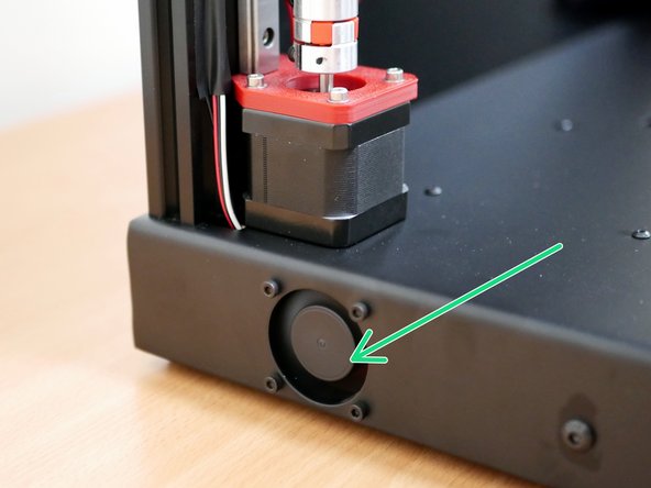
Check that the following are operating:
-
Electronics Fan
-
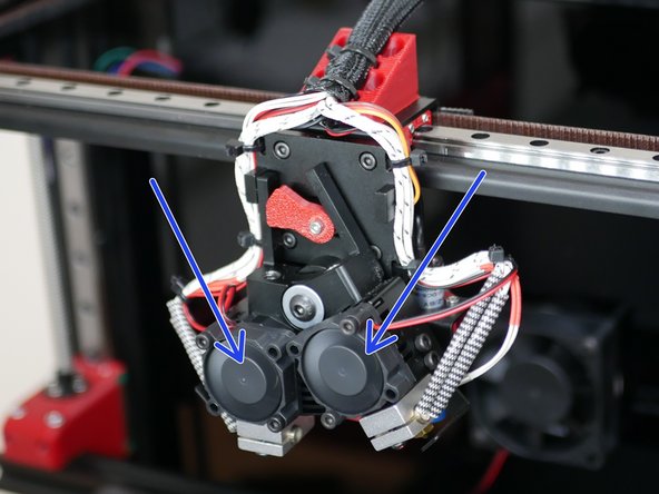
Hotend Fans
-
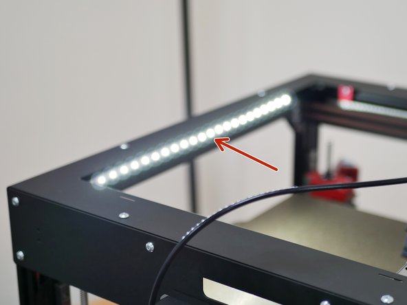
LED Lights
-
-
-
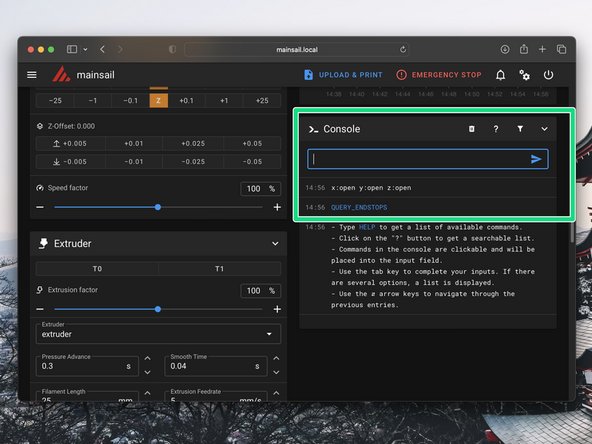
Make sure that none of the endstops on the printer are being mechanically triggered.
-
In the Mainsail console send the command QUERY_ENDSTOPS
-
The end stops should all return open.
-
One by one, trigger the end stops and the probe (by placing a metal object under it) and resend the QUERY_ENDSTOPS command.
-
Verify that each endstop and the probe are functioning correctly.
-
-
-
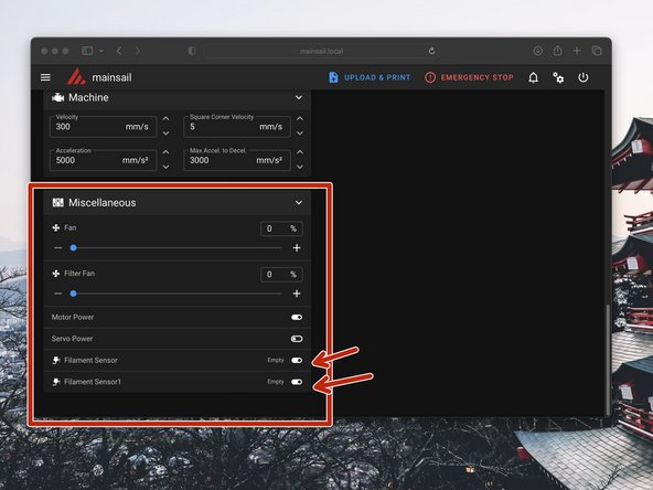
Scroll down the dashboard on Mainsail.
-
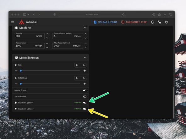
You should then see in the Miscellaneous box Filament Sensor readouts.
-
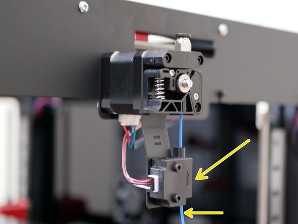
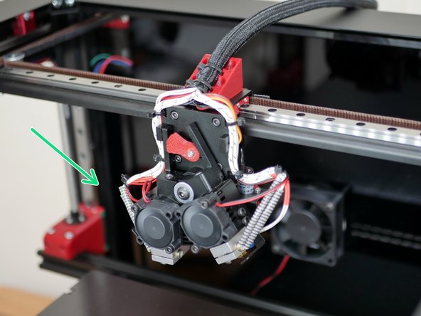
Load filament into the extruder and check that these are correctly updating.
-
Sensor 0 is the left extruder.
-
Sensor 1 is the right extruder.
-
-
-
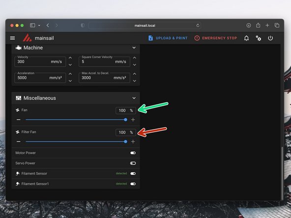
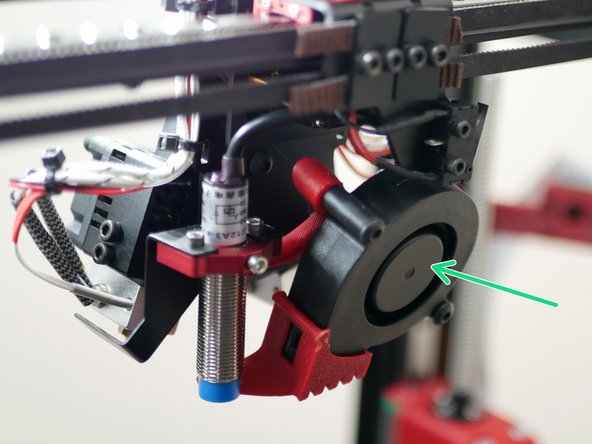
Set the part cooling fan to 100%.
-
Check that it is spinning.
-
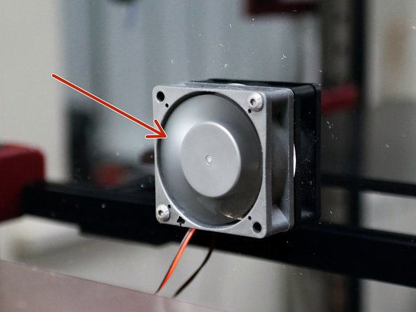
Set the fume filter fan to 100%.
-
Check that it is spinning.
-
-
-
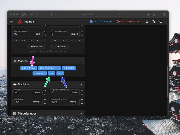
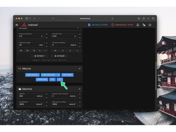
If needed, use Arm Install to set the servo angle to 90 degrees. In this position the servo arm can be installed vertically.
-
Use the T0 and T1 macro to check that the switching hotend is working properly.
-
T0
-
T1
-
If need be the servo angles can be adjusted in the variables.cfg file.
-
-
-
Manually move the tool head to roughly the centre of the print area. Also make sure that the platform is not set all the way to the top or bottom, but somewhere safe in the middle.
-
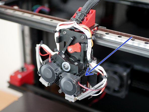
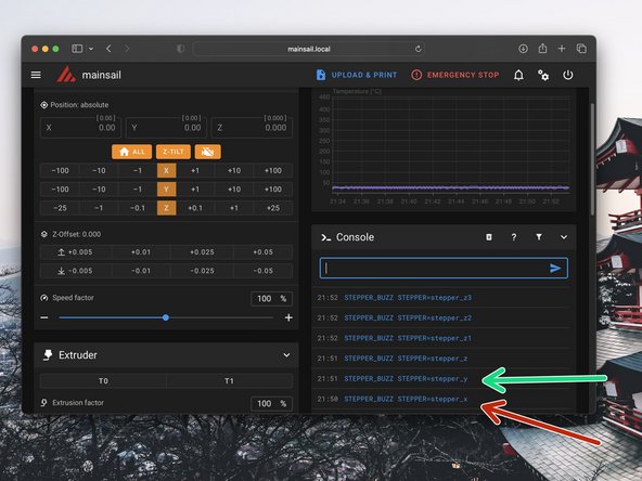
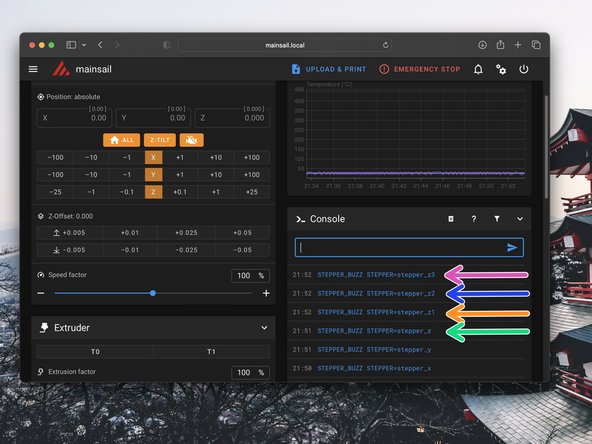
Send the command: STEPPER_BUZZ STEPPER=stepper_x
-
This will move the the x-motor (the motor on the right) clockwise by a small amount and then return it to its original position. It will do this several times.
-
Send the command: STEPPER_BUZZ STEPPER=stepper_y
-
This will move the the y-motor (the motor on the left) clockwise by a small amount and then return it to its original position. It will do this several times.
-
If the above described movements do not occur, power down and double check you wiring.
-
-
-
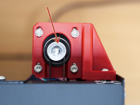
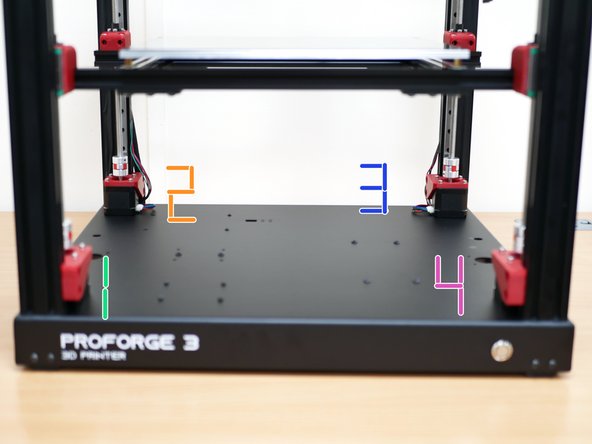
Send the command: STEPPER_BUZZ STEPPER=stepper_z
-
This will move the the z-motor in the front left corner anti-clockwise by a small amount and then return it to its original position. It will do this several times.
-
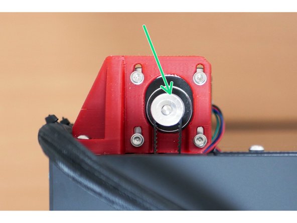
Send the command: STEPPER_BUZZ STEPPER=stepper_z1
-
This will move the the z-motor in the back left corner anti-clockwise by a small amount and then return it to its original position. It will do this several times.
-
Send the command: STEPPER_BUZZ STEPPER=stepper_z2
-
This will move the the z-motor in the back right corner anti-clockwise by a small amount and then return it to its original position. It will do this several times.
-
Send the command: STEPPER_BUZZ STEPPER=stepper_z3
-
This will move the the z-motor in the front right corner anti-clockwise by a small amount and then return it to its original position. It will do this several times. If the above described movements do not occur, power down and double check you wiring.
-
-
-
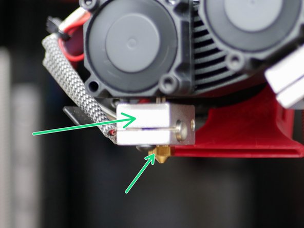
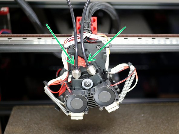
Hold the heater block with one set of pliers and tighten the nozzle down with the other set.
-
Switch to the second hotend and repeat.
-
-
-
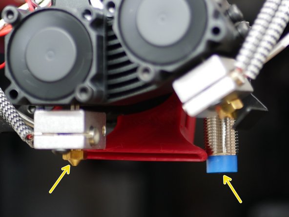
Adjust the Probe so that it sits below the tip of the nozzle.
-
Be careful when doing this, the hotend will be hot!
-
Place the flex plate back onto the platform, if you had removed it earlier.
-
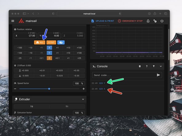
Send G28 X to home the X-axis. The print head should move to the left.
-
Send G28 Y to home the Y-axis. The print head should move to the front.
-
Finally press the home all button to home all of the axes together.
-
-
-
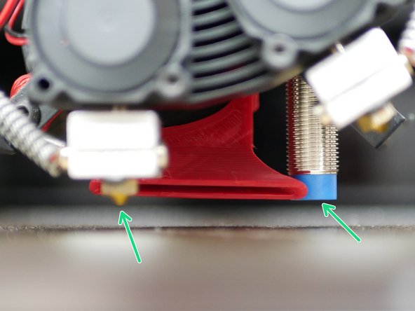
Adjust the probe again, but this time it should sit approx 2mm above the tip of the nozzle.
-
To be safe, double check by manually raising the platform that the probe triggers before the nozzle touches the build plate.
-
-
-
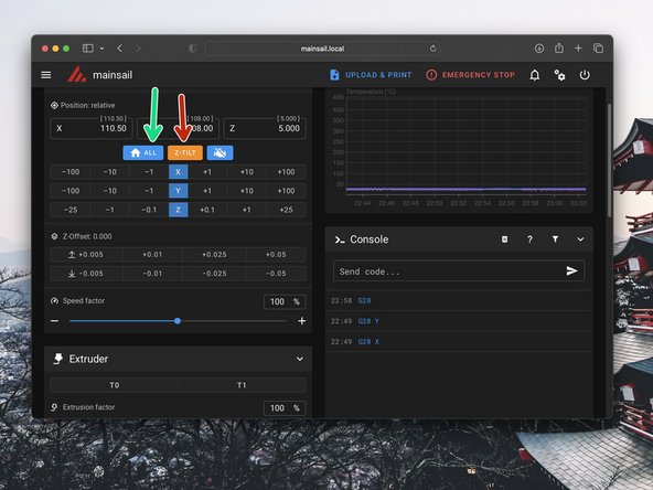
With the probe set in its final position, home all of the axes again.
-
Be ready for an emergency stop if the nozzle touches the bed before the probe triggers.
-
After homing successfully press the Z-TILT button to run the auto-levelling procedure.
-
-
-
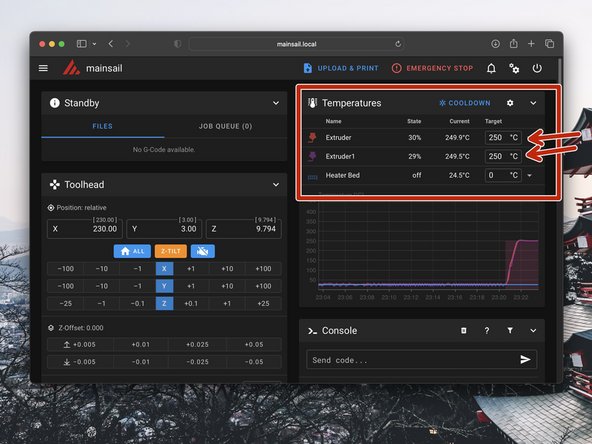
Heat the bed to an average printing temperature, around 80C.
-
We recommend waiting around 10-15 minutes for the beds temp to stabalize even after the temperature is reached according to the themistor.
-
Due to thermal expansion, the probe offset (set in the next step) will vary because of this.
-
-
-
Home all of the axes again.
-
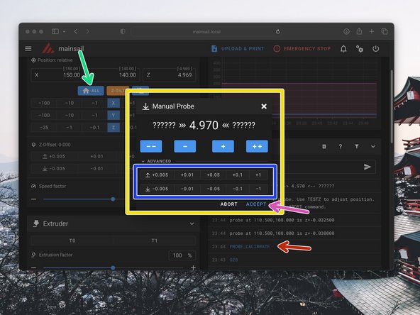
With the print head now in the centre of the print area and with the hotend and bed hot send the command PROBE_CALIBRATE
-
The print head will probe the bed and then move the nozzle to the probed location.
-
A box like this will appear in Mainsail.
-
Use these buttons to adjust the distance between the nozzle (left hotend) and the build plate.
-
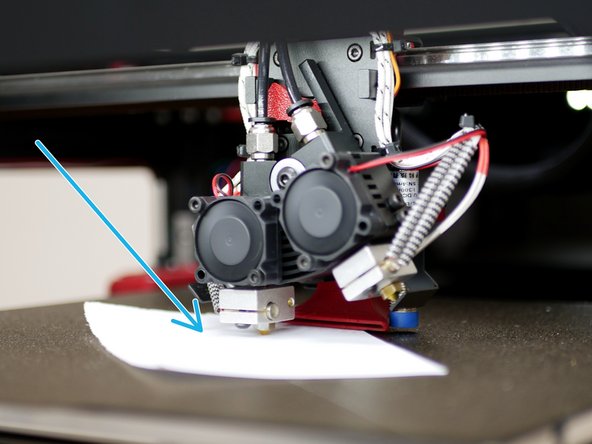
Place a piece of paper between the nozzle and build plate, adjust the distance until the nozzle grips the paper.
-
When happy hit accept.
-
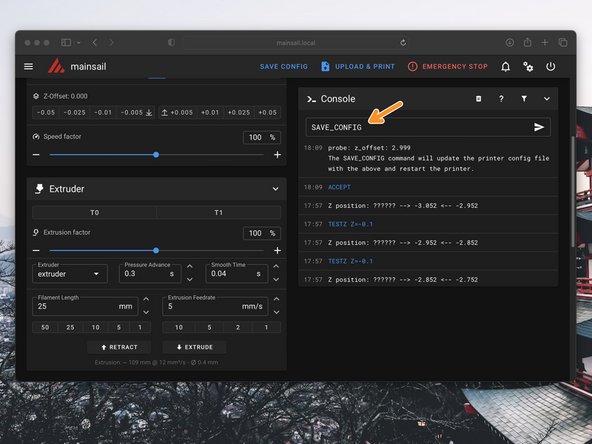
Send SAVE_CONFIG to save the offset.
-
-
-
Let the hotends and bed cool down.
-
Re-home the printer.
-
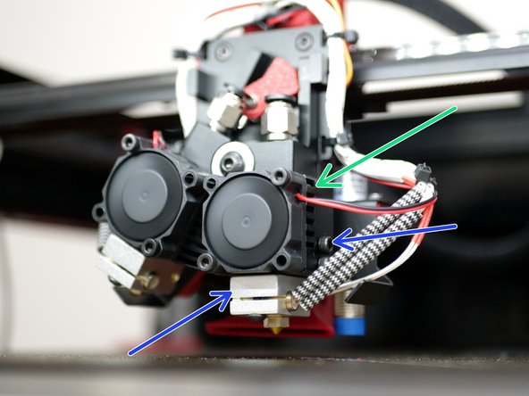
Switch to the second hotend.
-
Loosen the bolts holding the heat-break in the heatsink and raise the heater block up and secure the bolts.
-
-
-
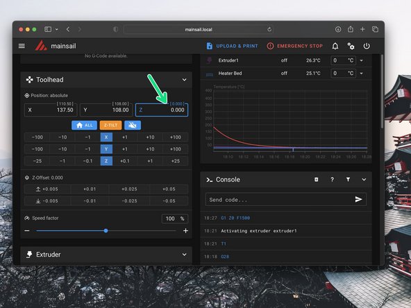
Place a piece of paper between the nozzle and the build plate.
-
Set the Z axis to 0.
-
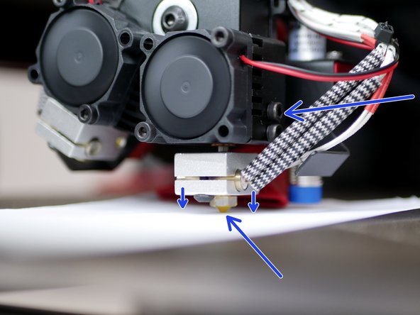
Loosen the bolts holding the second heater block and lower it down until the piece of paper is trapped between the nozzle and bed.
-
Tighten the bolts to secure the heater block in place.
-
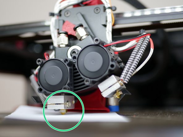
Switch back to T0, check that the friction with the piece of paper between the two nozzles and the platform is the same.
-
If you need to make adjustments, make them only to the second hotend.
-
-
-
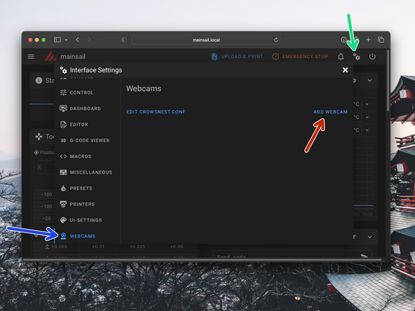
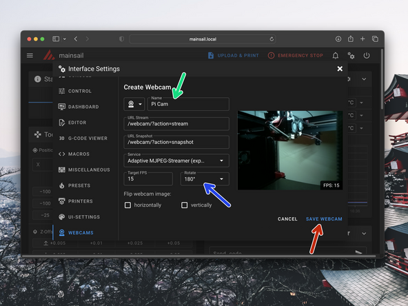
Name the webcam Pi Cam
-
Rotate the camera 180 degrees.
-
Hit SAVE WEBCAM to complete.
-


Cancel: I did not complete this guide.
3 other people completed this guide.
