
-
-
Prepare the Z-Axis Bracket
-
Two M5 x 8mm bolts
-
Two M5 T-Nuts
-
Orient as shown in the photos.
-
-
-
Fix the 2020 x 450mm Beam onto the Z-Axis Bracket.
-
Make sure the distance between the edge of the z-axis bracket and beam is 40mm for the Proforge 2 and 50mm for the Proforge 2S
-
Keep as straight and square as possible to the bracket. Use the part of the bracket that comes out to help gauge this.
-
-
-
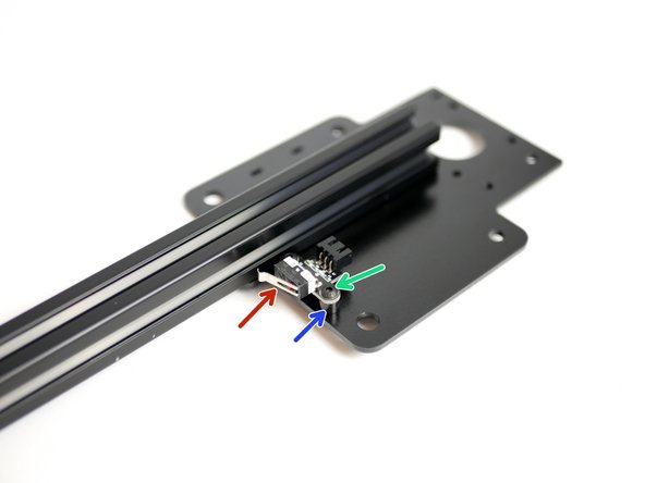
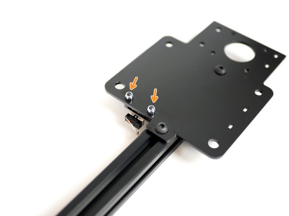
Install the Endstop onto the Z-Axis Bracket.
-
Two M3 x 14mm bolts
-
Two M3 x 5mm Spacers
-
Two M3 Nyloc Nuts
-
-
-
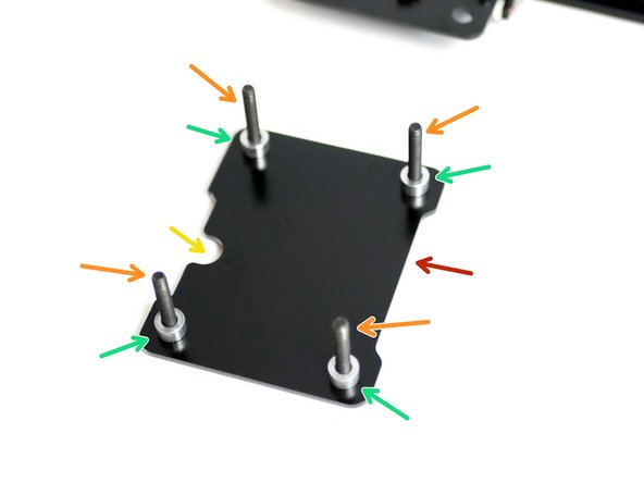
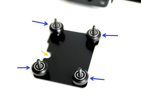
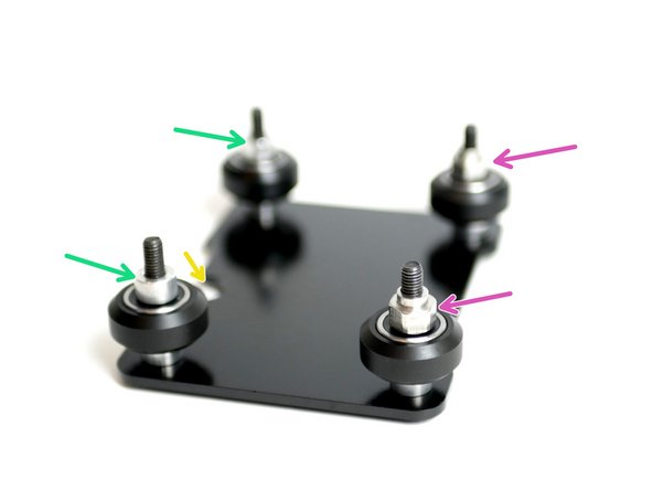
Prepare the Z-axis support bracket with rollers and spacers:
-
Z-Axis Support Bracket
-
The support bracket should be oriented so that the circular cut out should be on the lower left.
-
Four M5 x 35mm Bolts
-
Six M5 x 6mm aluminium spacers. Four beneath the Roller Wheels, two above the Roller Wheels on the same side as the cutout
-
-
Two Eccentric Spacers. opposite side of the cutout
-
Match the direction of the eccentric spacer in third image.
-
-
-
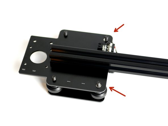
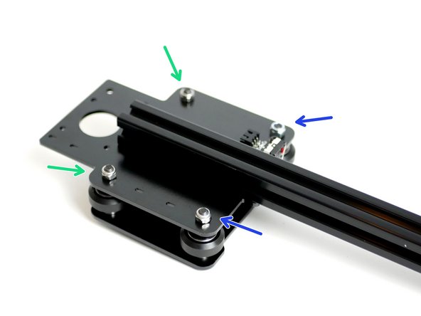
Place carefully over the spacer/roller stack the main Z-Axis Bracket Assembly.
-
Match the photographs, the eccentric spacers should be on the side of the endstop.
-
Tighten firmly the Nuts that are holding together the rear side of the assembly.
-
Tighten loosely the nuts holding together the front of the assembly with the eccentric spacers.
-
The eccentric spacers should be able to turn freely - they will be tightened later.
-
-
-
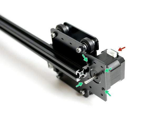
Fix a NEMA 17 Motor onto the bracket as shown in the image.
-
Four M3 x 6mm bolts.
-
Orient the Motors cable connector upwards.
-


Cancel: I did not complete this guide.
29 other people completed this guide.
