
-
-
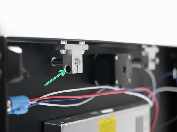
Fix the lead screw nut onto the platform panel as shown.
-
Lead Screw Nut
-
M3 x 6mm Cap
-
Repeat for both panels
-
Note the orientation of the nut in relation to the panel also.
-
-
-
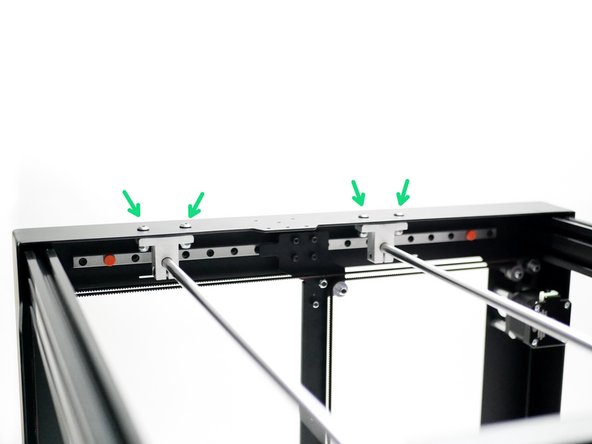
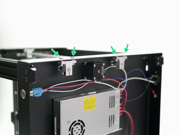
Secure two LMK8LUU linear bearings onto the panels like shown.
-
LMK8LUU
-
M3 x 6mm Cap
-
Repeat for both Panels
-
Note the orientation of the bearings in relation to the panels also.
-
-
-
Place the printer onto its side.
-
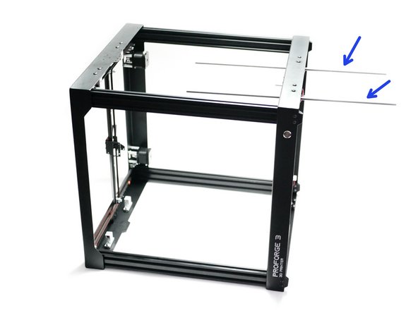
Slide two z-rods in through the mounts on the base.
-
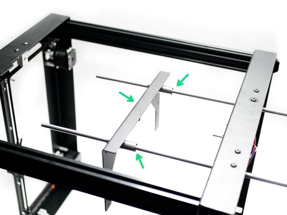
Slide one of the platform panel assemblies onto the rods like shown.
-
The mounts themselves should at this stage only be fastened on loosely, as instructed in the base and top panel assembly notes.
-
-
-
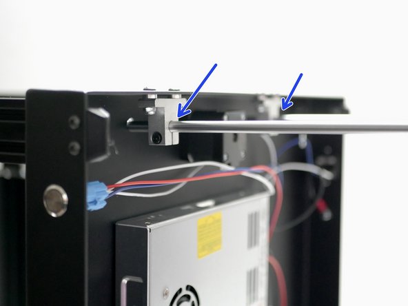
Push the shafts all the way up into the brackets on the top panel.
-
Secure the shafts onto the mounts by firmly tightening the M4 bolts on each bracket.
-
-
-
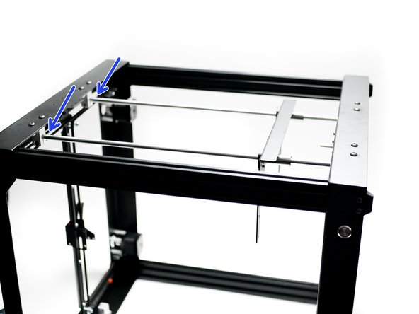
With the mounts now clamping down onto the rods, it is time to firmly secure the brackets to the panels.
-
Repeat this for the other side also.
-
-
-
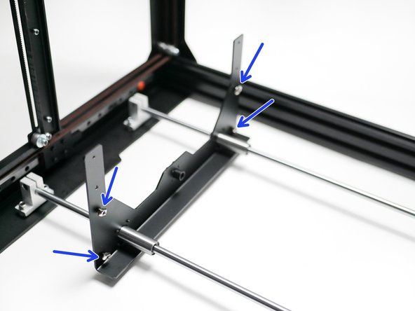
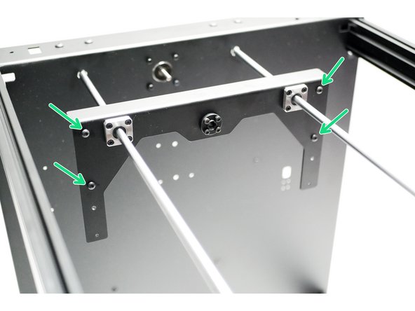
Loosely fasten M4 x 6mm bolts and M4 t-nuts onto the fours holes on the platform panels like shown.
-
Note the orientation, the T-nuts should point towards the base.
-
M4 x 6mm
-
M4 T-Nut
-
Repeat for the other platform panel also.
-
-
-
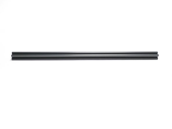
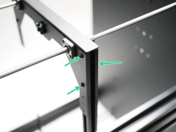
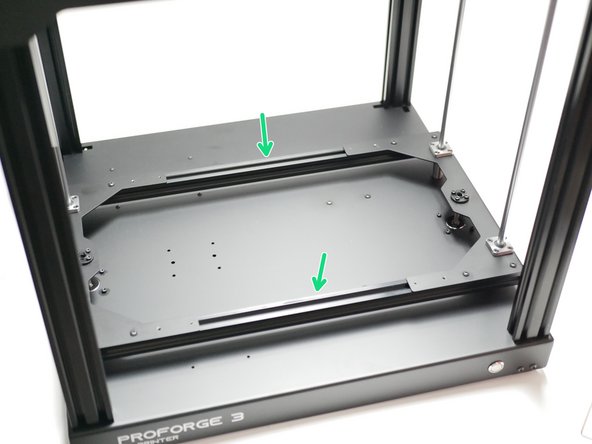
Take the 2020 extrusions and secure them to the platform panels like shown.
-
-
-
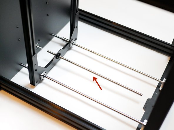
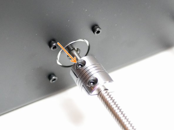
Screw the lead screw into the lead screw nut.
-
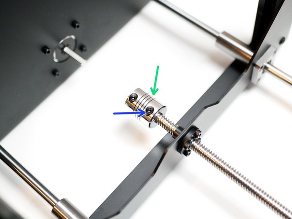
Take a coupling and push it all the way onto the leadscrew,
-
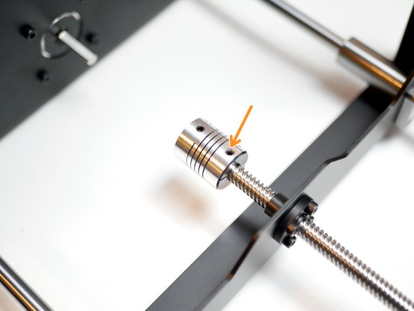
Tighten this bolt to clamp the coupling in place on the lead screw.
-
Finally, tighten the set screw on the coupling also.
-
-
-
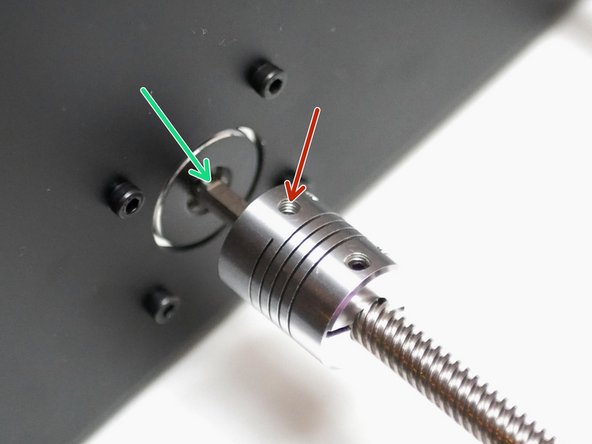
Slide the coupling onto the z-motor shaft.
-
Secure the set screw onto the flat side of the shaft.
-
Set screw
-
Flat side of motor shaft
-
Finally clamp the coupling in place by tightening this bolt.
-
-
-
Secure the cable relief bracket to the rear 2020 extrusion like shown with an M4 x 6mm bolt and M4 T-nut.
-
Fix it approximately an inch from the left platform panel.
-


Cancel: I did not complete this guide.
7 other people completed this guide.
