
-
-
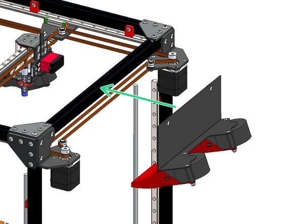
Build the static cooling fan assembly as shown:
-
Static Cooling Fan Bracket
-
70mm Blower Fan (x2)
-
3D Printed Static Fan Shroud (x2)
-
M4 x 40mm Button Head Bolt (x4)
-
M4 Nyloc Nut (x4)
-
-
-
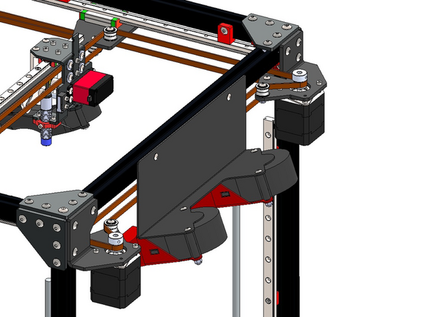
Loosely fasten on two M4 x 6mm bolts and M4 T-nuts onto the static cooling fan assembly as shown.
-
-
-
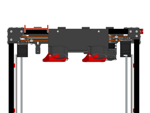
Fix the static cooling fan assembly onto the right side of the frame as shown.
-
Install the assembly approximately 94mm from the edge of the motor bracket.
-
-
-
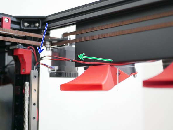
Route the fan cables to the rear of the printer - use a cable tie to keep them together.
-
They will be routed down the rear extrusion in the final wiring stage.
-
-
-
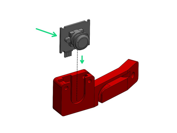
Drop the camera into the 3D printed case as shown.
-
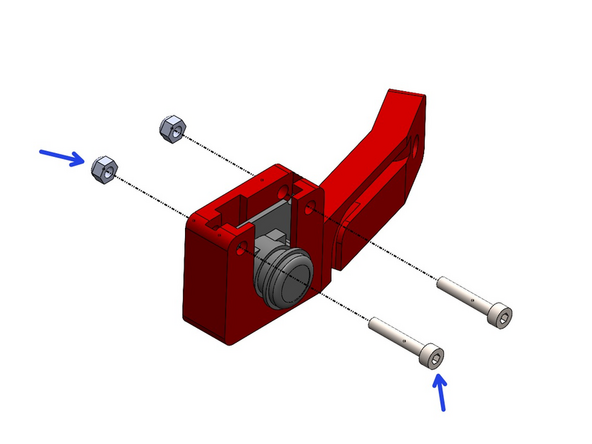
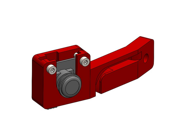
Use two M3 x 18mm bolts with M3 nyloc nuts to hold it in place.
-
-
-
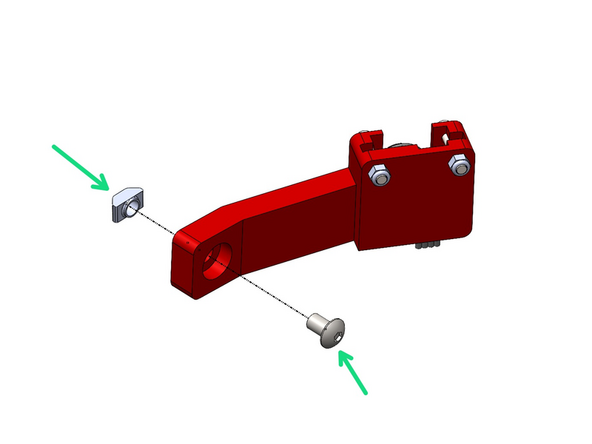
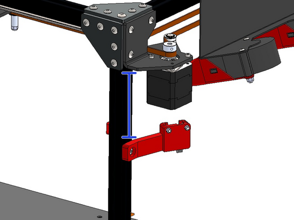
Use an M5 x 8mm bolt and M5 T-nut to mount the camera to the right side of the frame.
-
Mount it approximately 10CM from the bottom of the motor bracket.
-
-
-
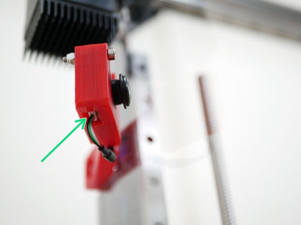
Feed the camera cable through the base first (the USB side is too big to fit).
-
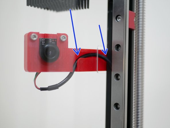
Connect the USB camera cable to the camera module as shown.
-
Route the cable through the case and down the extrusion.
-


Cancel: I did not complete this guide.
16 other people completed this guide.
