
-
-
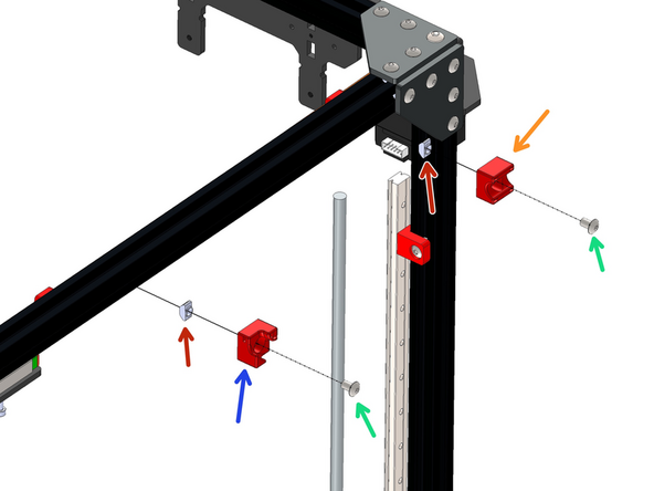
Prepare 6 rail mounts as shown by loosely fastening an M5 T-nut onto the M5 bolt.
-
M5 x 8mm Bolt
-
M5 T-nut
-
-
-
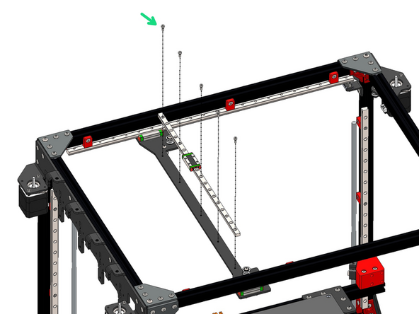
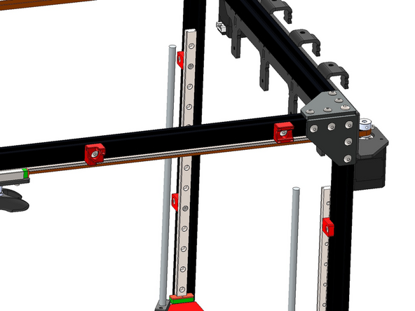
Fix the rail mount assemblies from the previous steps onto the two 550mm long MGN12 rails.
-
Space them out as shown with two fixed one from the edge and the third in roughly the centre.
-
M3 x 6mm Cap Bolt
-
Use the orange stoppers to prevent the carriage from falling off the rail. It is important to not let it fall of as this could cause the small ball bearings to fall out of the carriage.
-
-
-
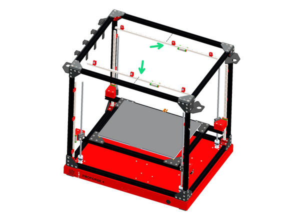
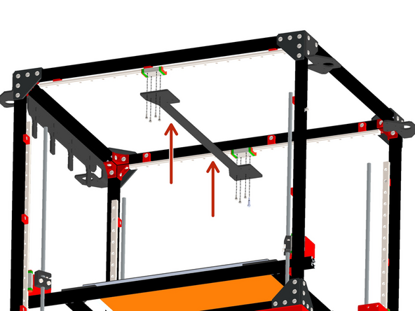
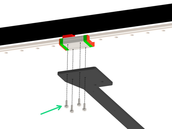
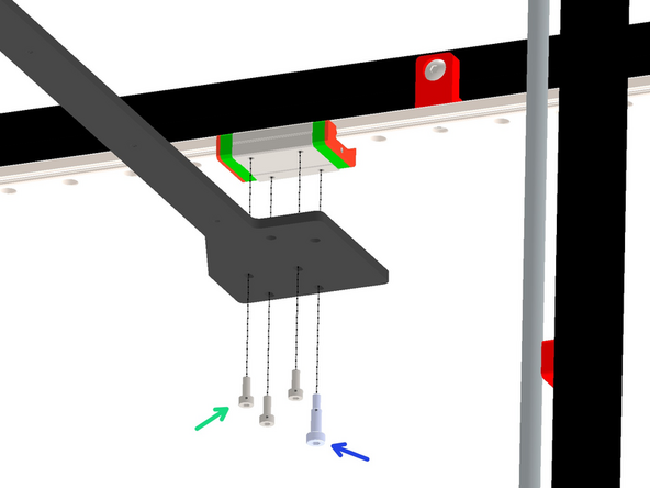
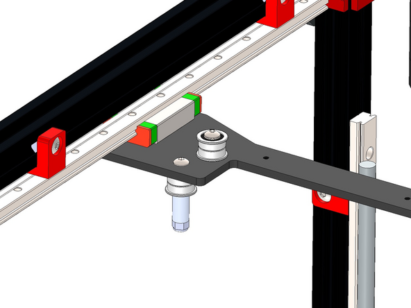
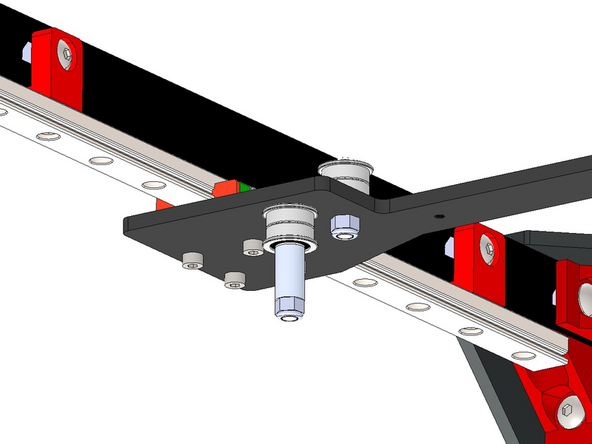
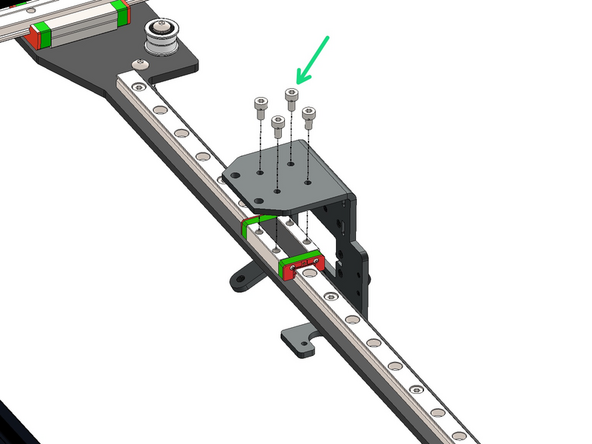
Mount the gantry panel onto the carriages.
-
M3 x 8mm Cap
-
M3 x 10 x 6 Sholder Bolt
-
Match the orientation of the gantry bracket as shown.
-
-
-
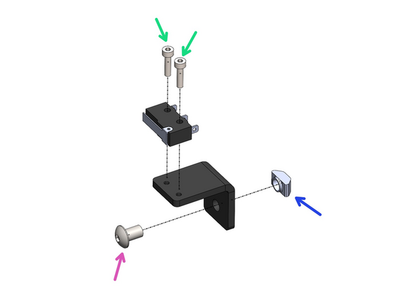
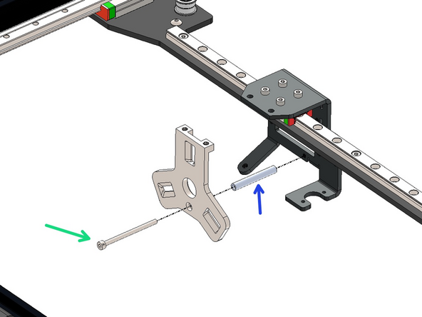
Assemble an endstop to the X-Endstop Bracket.
-
M2.5 x 10mm Cap
-
Loosely fasten on an M5 bolt and T-nut
-
M5 x 8mm
-
M5 T-nut
-
-
-
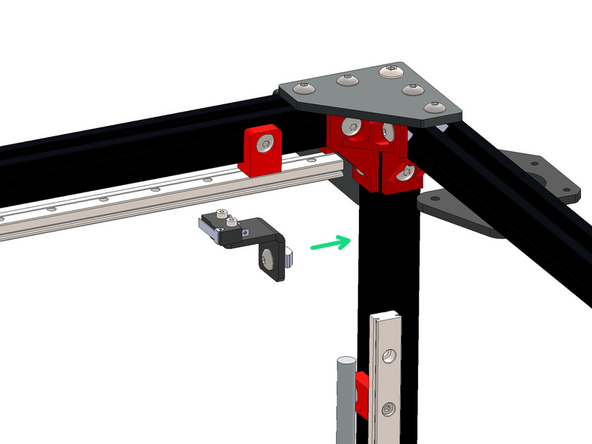
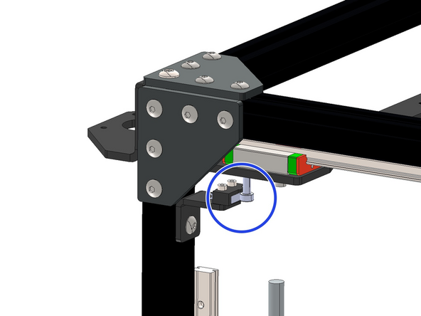
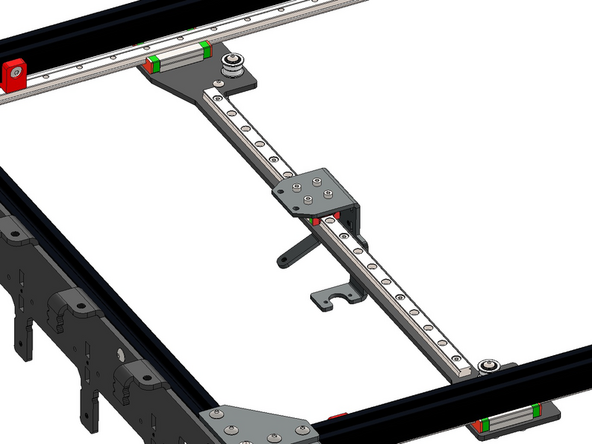
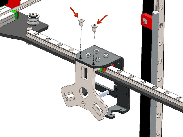
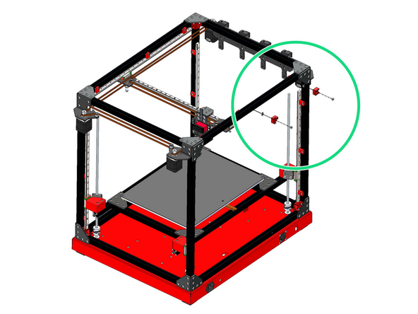
Mount the X-Endstop Assembly to the inside of the frame on the rear right side.
-
Align the endstop switch with the shoulder bolt on the gantry - It should trigger the endstop when the gantry is moved all the way to the right.
-
-
-
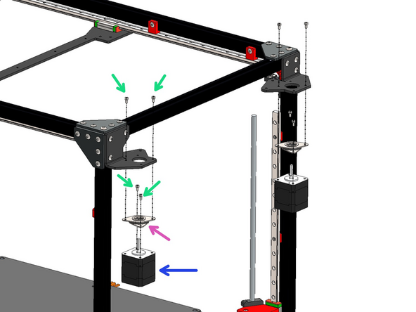
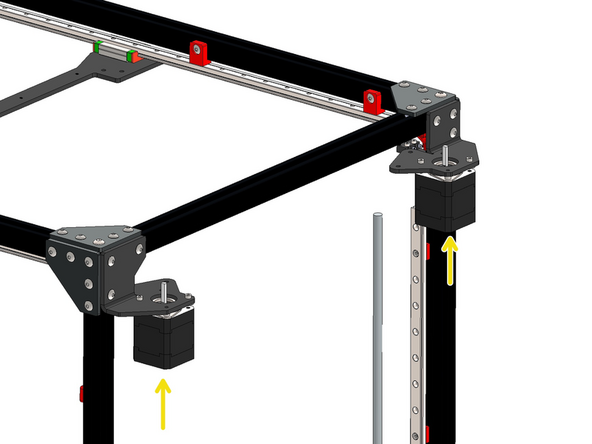
Install the LDO motors to the frame with the motor dampeners.
-
M3 x 6mm Cap Bolt
-
Motor Dampener
-
LDO NEMA 17 Motor
-
Install the motor so that the cable connector faces inwards.
-
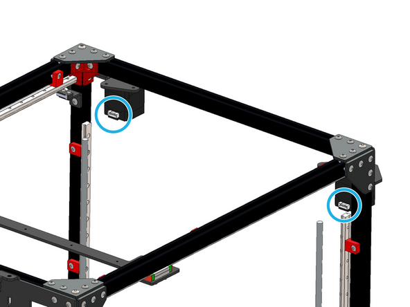
Finally add the heatsinks to the underside of the motors.
-
Use the cables that came with the LDO motors with the LDO motors and NOT the BIQU Z-motors. We recommend placing these cables back into the LDO box until the wiring stage.
-
-
-
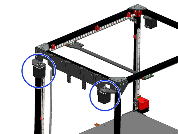
Repeat the process for the motors on the other side of the frame.
-
Again, it's very important to use the cables that came with the LDO motors with the LDO motors and NOT the BIQU Z-motors. We recommend placing these cables back into the LDO box until the wiring step.
-
-
-
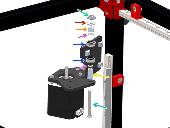
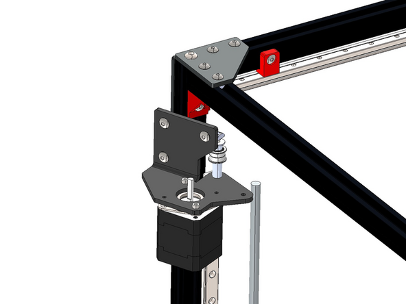
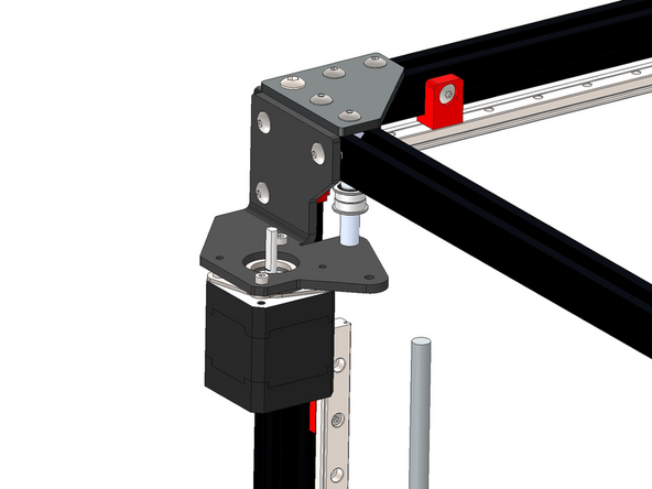
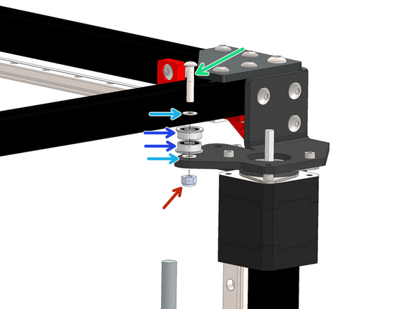
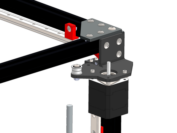
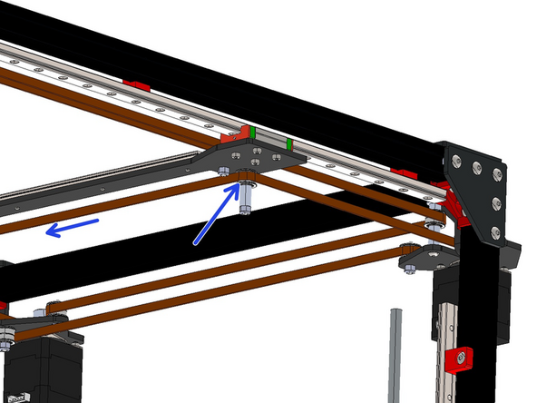
You will need to unmount the bracket to gain access for assembling this idler stack, re-mount it to the frame after building the Idler stack by also fixing the M4 x 40mm bolt to the top extrusion.
-
M4 T-nut
-
M4 Penny Washer
-
M4 x 5mm Spacer
-
M4 x 8 x 0.5mm Shim
-
F624ZZ Bearing
-
M4 x 15mm Spacer
-
M4 x 40mm Button bolt
-
-
-
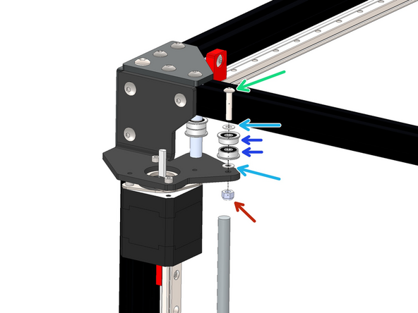
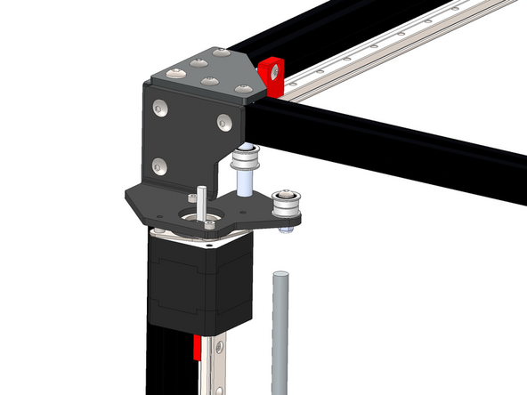
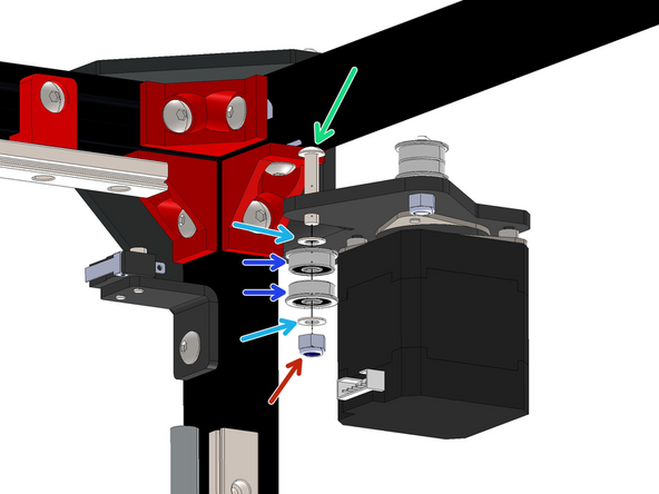
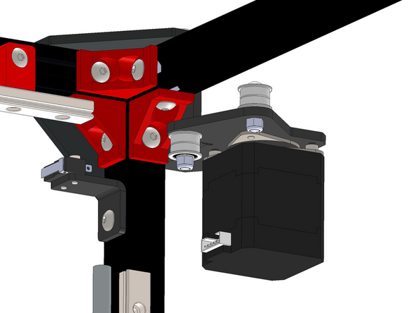
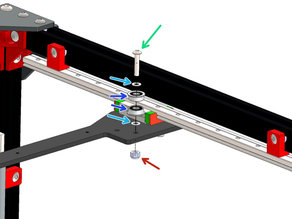
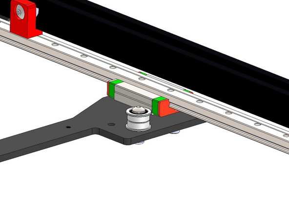
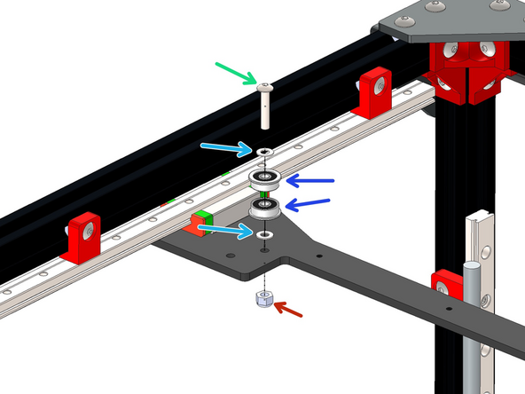
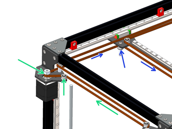
Assemble the second idler stack to the same front right motor bracket as shown.
-
M4 x 20mm Button
-
M4 x 8 x 0.5mm Shim
-
F624ZZ Bearing
-
M4 Nyloc Nut
-
-
-
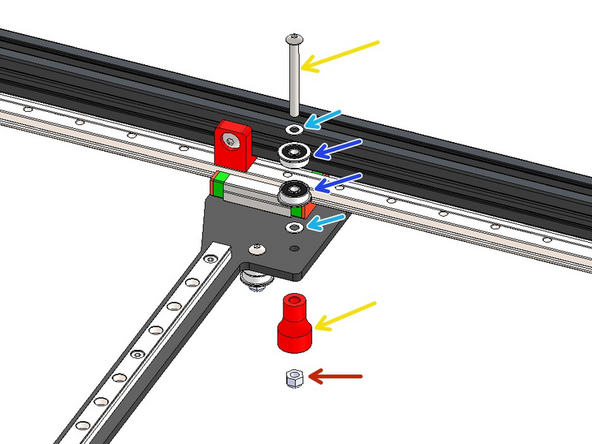
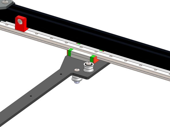
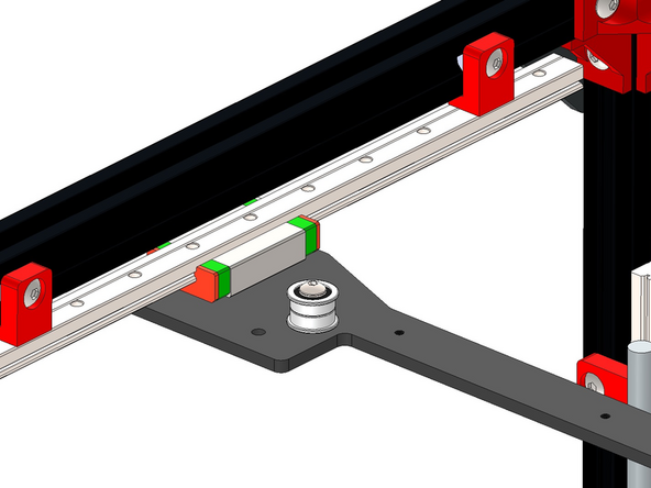
Assemble the Idler stack to the rear right motor bracket as shown.
-
M4 x 20mm Button Bolt
-
M4 x 8 x 0.5mm Shim
-
F624ZZ Bearing
-
M4 Nyloc Nut
-
-
-
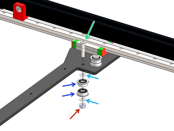
Install the second Idler stack to the rear right motor bracket as shown.
-
M4 x 20mm Button bolt
-
M4 x 8 x 0.5mm Shim
-
F624ZZ Bearing
-
M4 Nyloc Nut
-
-
-
Build the Idler stack as shown on the far side of the gantry bracket.
-
M4 x 20mm Button Bolt
-
M4 x 8 x 0.5 mm Shim
-
F624ZZ Bearing
-
M4 Nyloc Nut
-
If you're building v4.2 use an M4 x 40mm bolt and add the 3d printed endstop trigger.
-
-
-
Build the second Idler stack as shown on the far side of the gantry bracket.
-
M4 x 20mm Button Bolt
-
M4 x 8 x 0.5mm Shim
-
F624ZZ Bearing
-
M4 Nyloc Nut
-
-
-
Build the third Idler stack as shown on the near side of the gantry bracket.
-
M4 x 20mm Button Bolt
-
M4 x 8 x 0.5mm Shim
-
F624ZZ Bearing
-
M4 Nyloc Nut
-
-
-
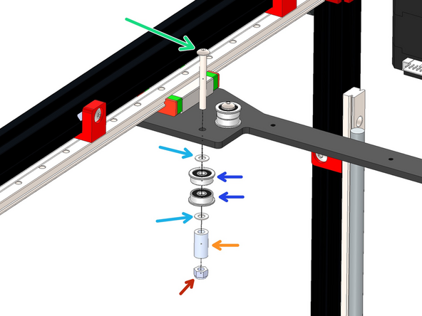
Build the fourth Idler stack as shown on the near side of the gantry bracket.
-
M4 x 35mm Button Bolt
-
M4 x 8 x 0.5mm Shim
-
F624ZZ Bearing
-
M4 x 15mm Spacer
-
M4 Nyloc Nut
-
-
-
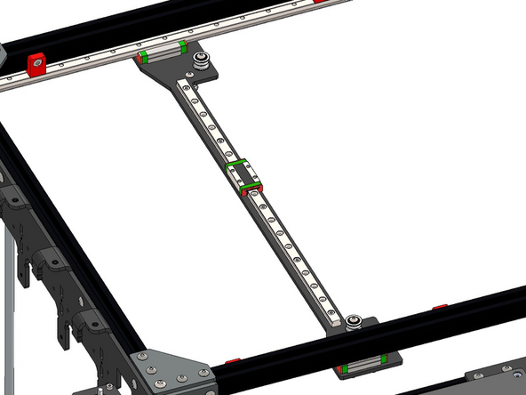
Mount the MGN9 rail onto the gantry.
-
M3 x 8mm Cap Bolt
-
Take care to not let the carriage fall of the rail. Use the orange stoppers for this.
-
-
-
Fix the Tool Changer Bracket onto the rail carriage.
-
M3 x 6mm Cap Bolt
-
-
-
Fix the Master Plate onto the tool changer bracket.
-
M3 x 45mm Cap Bolt
-
3mm x 35mm Spacer
-
M4 x 6mm Button
-
-
-
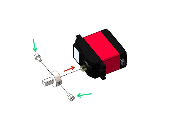
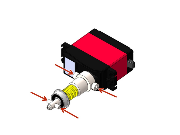
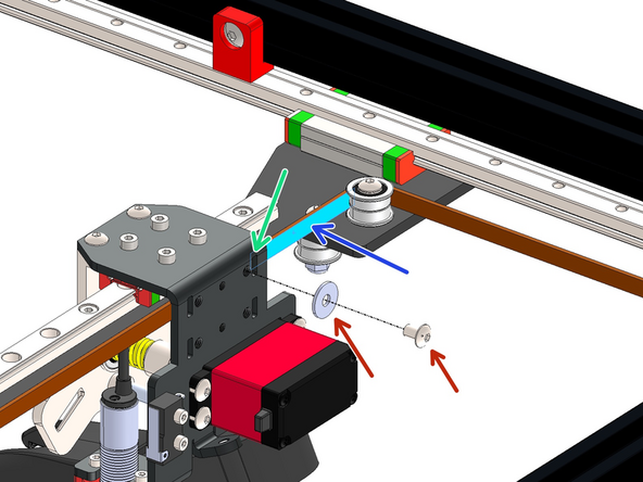
Loosely fix on two M3 x 5mm bolts to the Tool Changer Drive Shaft
-
Then slide it onto the servo motor
-
-
-
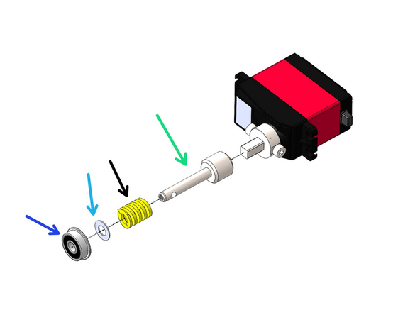
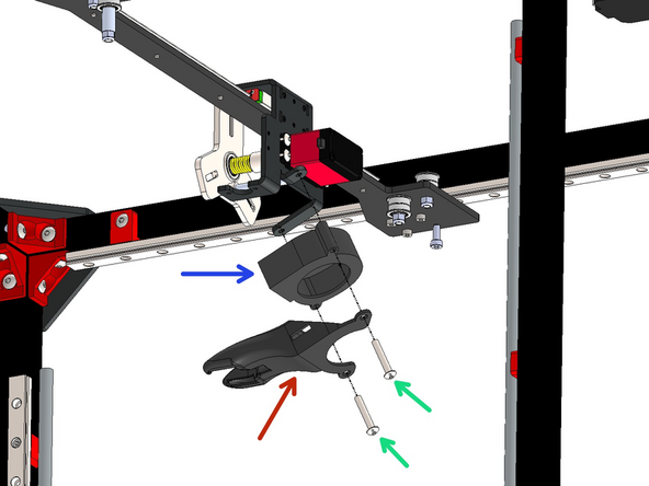
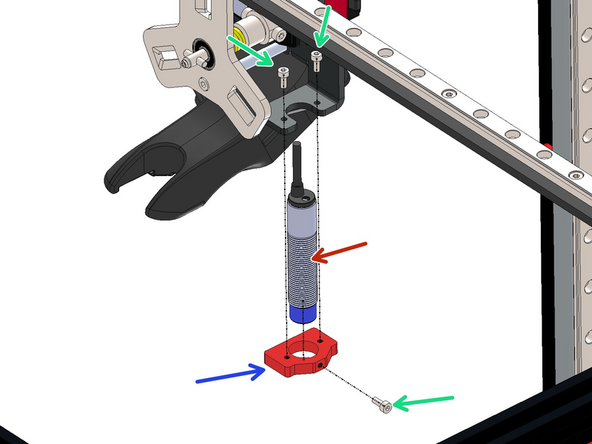
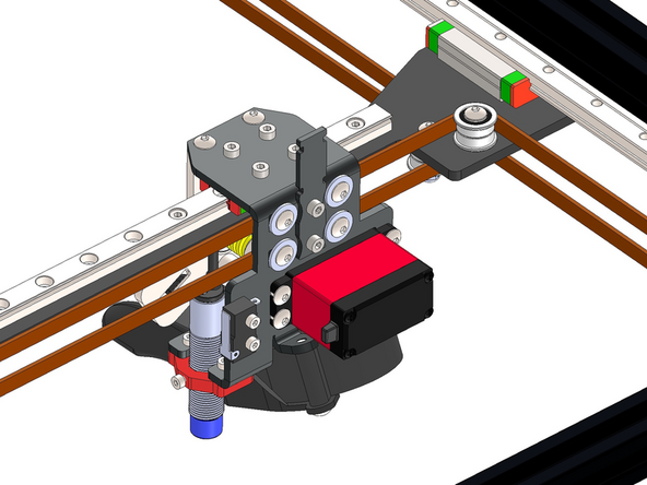
Build the Tool Changer Mechanism as shown
-
Tool Changer - Cam Shaft
-
Spring
-
M5 x 10 x 0.5mm Shim
-
F605ZZ Bearing
-
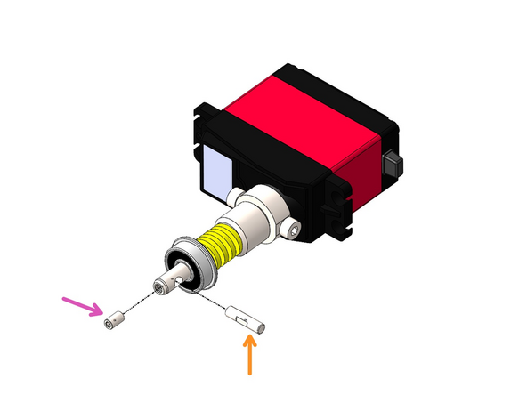
Cam Pin
-
M3 x 4mm Grub Screw - Tighten the grub screw against the flat side of the cam pin.
-
Make sure the cam pin is aligned with the bolts on the drive shaft.
-
-
-
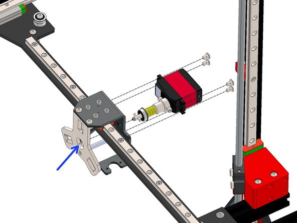
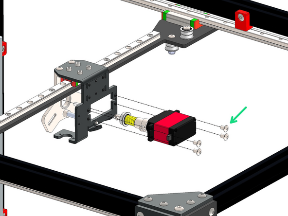
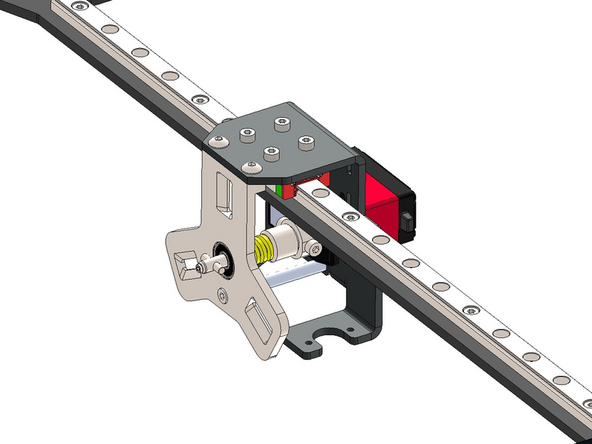
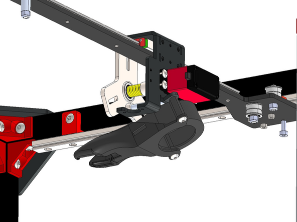
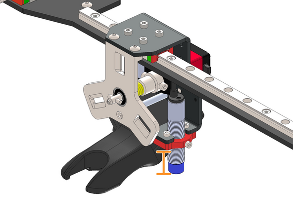
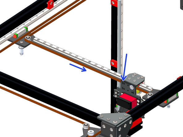
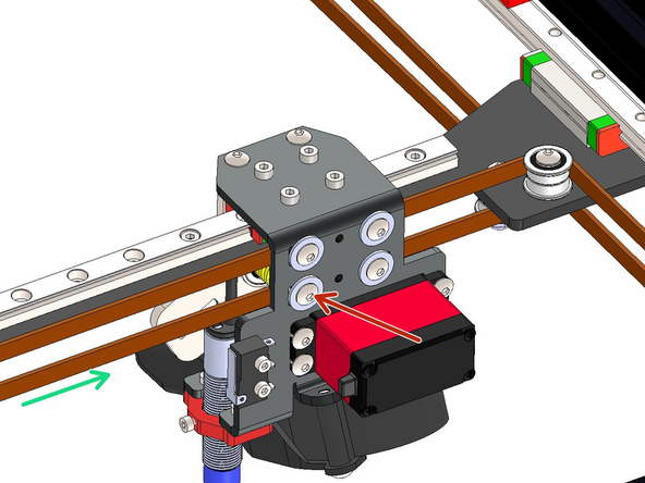
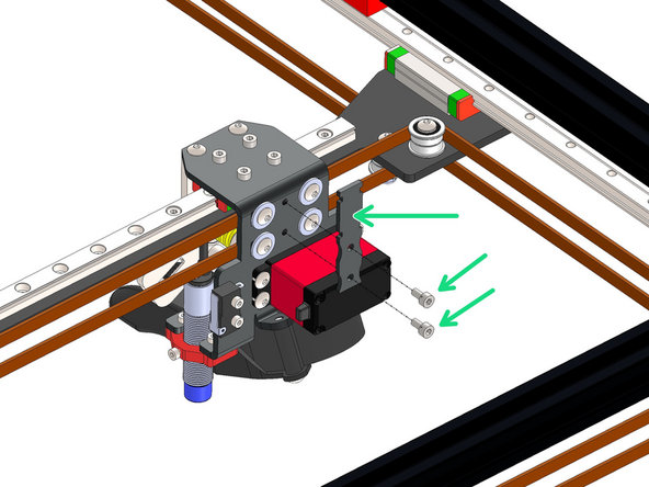
Slide the assembly in through the rear of the carriage bracket and into the hole on the master plate as shown.
-
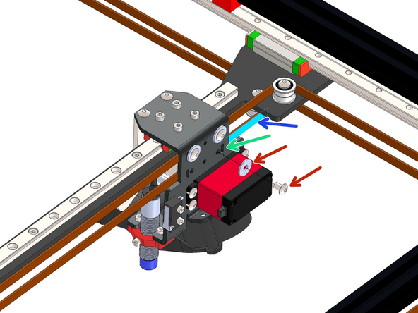
Fix the servo in place with four M4 x 6mm Bolts
-
-
-
Fix the 50mm blower fan to the tool changer assembly.
-
M4 x 25mm Button
-
3D Printed Fan Shroud
-
50mm Blower Fan
-
Do not over tighten, the shroud is 3d printed and could snap.
-
-
-
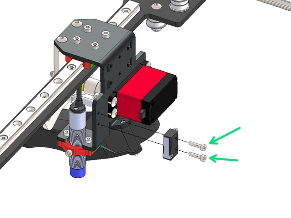
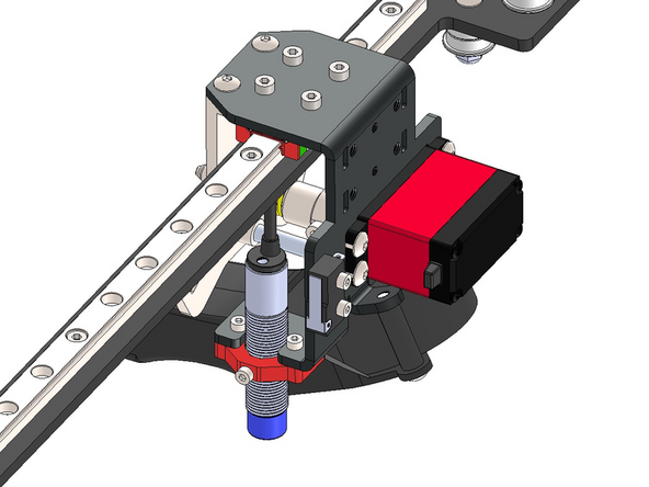
Install the probe by sliding it into the probe mount.
-
Then fix the assembly to the bracket.
-
M2.5 x 6mm Bolt (x3)
-
Approx. 25mm
-
The position of the probe will be adjusted later.
-
-
-
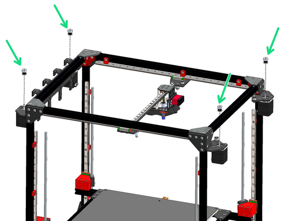
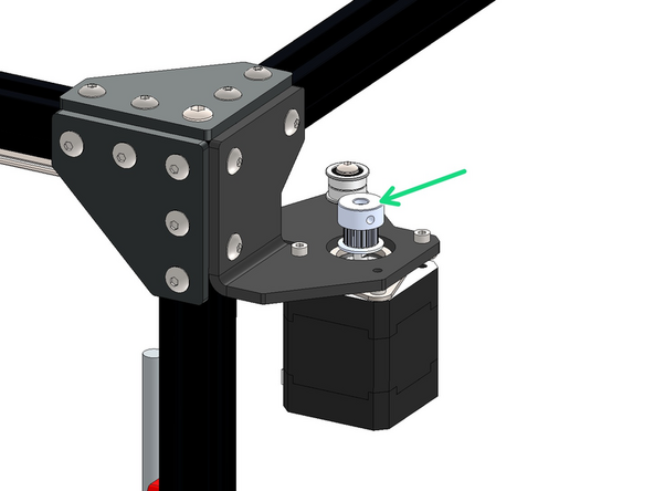
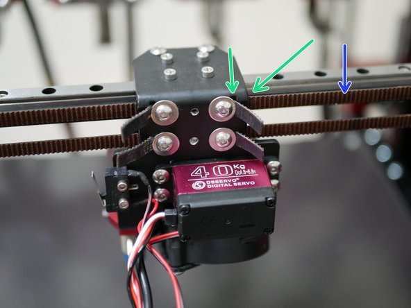
Drop pulleys onto each of the four motors.
-
Orientate so that the pulley teeth are facing downwards.
-
Do not tighten yet.
-
-
-
Take the 5m roll of GT2 belt and cut it in half.
-
Aim to get both halves as equal in length as possible.
-
Take an end of one of the belts and feed it in through the top right slit on the back of the carriage bracket.
-
It needs to be fed in from the inside of the bracket - you will need to temporarily remove the bracket from the linear rail carriage to gain better access.
-
Ensure that the belts teeth are facing out.
-
Fix the belt in place with an M4 x 6mm bolt and M4 penny washer.
-
-
-
Wrap the belt around the idler on the gantry.
-
Next feed it around the pulley on the rear right motor's pulley and idler.
-
-
-
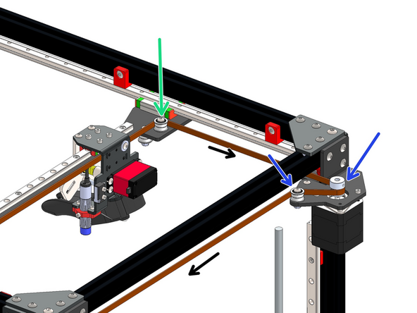
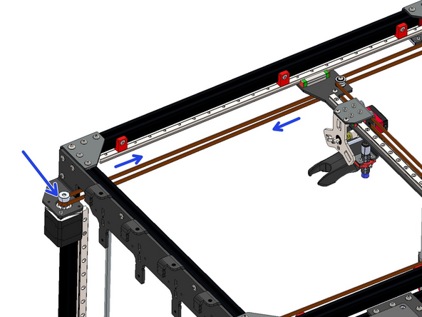
Next feed the belt across the top and to the idler on the other motor bracket.
-
-
-
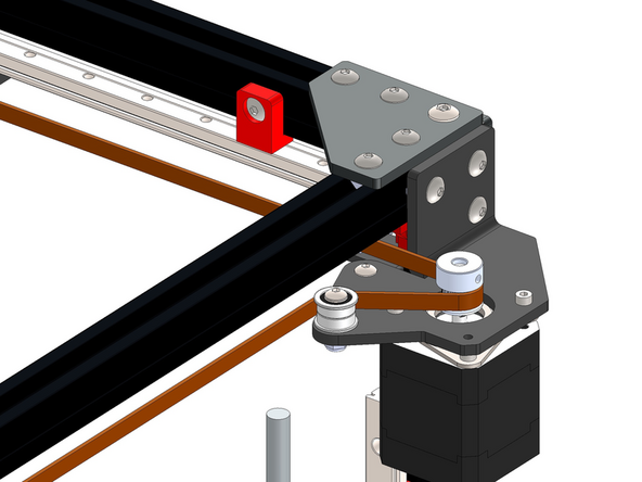
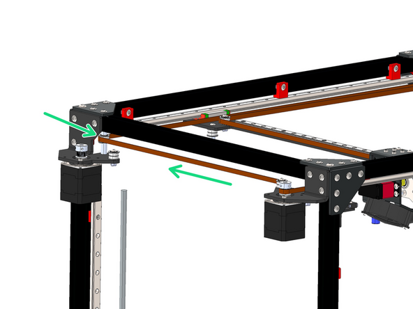
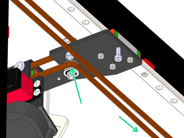
Next feed the belt down the long side of the frame going over the gantry bracket.
-
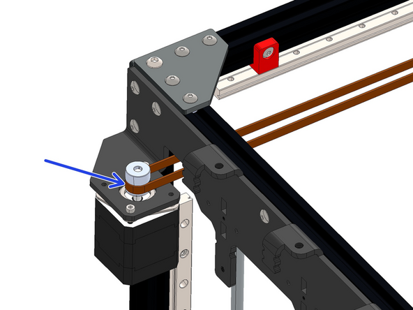
Wrap the belt around the front left motor's pulley.
-
-
-
Feed the belt back down the long side of the frame and around the pulley on the gantry bracket.
-
Fix the end of the belt into the slot on the top left of the bracket - again feeding it in from the inside of the bracket.
-
Secure the belt with an M4 x 6mm bolt and M4 penny washer - do not fully tighten down this bolt yet, as we will be tensioning this belt later.
-
-
-
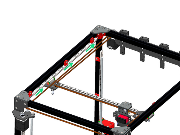
Take an end of one of the belts and feed it in through the slit on the back of the carriage bracket.
-
Again, it needs to be fed in from the inside of the bracket - you may need to temporarily remove it from the linear rail carriage to gain better access.
-
Ensure that the belts teeth are facing out.
-
Fix the belt in place with an M4 x 6mm bolt and M4 penny washer.
-
-
-
Start by wrapping the belt around the idler on the underside of the gantry bracket.
-
Next feed it around the pulley on the rear left motor.
-
-
-
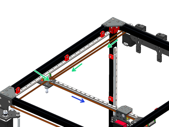
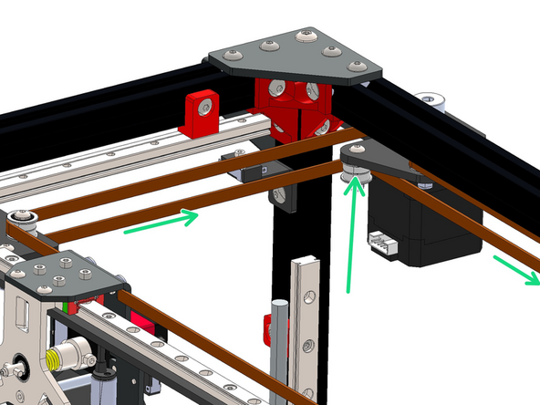
Feed the belt down the long side of the frame and wrap it around the idler on the rear right side motor bracket.
-
-
-
Feed the belt around the idler and pulley on the front right motor bracket.
-
Next feed the belt around the idler on the bottom of the gantry.
-
-
-
Finally feed the end of the belt into the slot on the bottom left of the bracket - again feeding it in from the inside of the bracket.
-
Secure the belt with an M4 x 6mm bolt and M4 penny washer - do not fully tighten down this bolt yet, as we will be tensioning the belts in the next step.
-
-
-
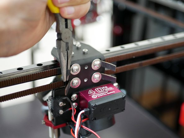
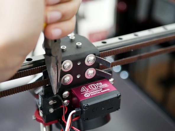
Use the included pair of plies to tension the belts.
-
Loosen these bolts enough to be able to pull the belt with the pliers but also hold the tension without letting the belts slip back.
-
Tension the belts as equally as possible.
-
Tension both belts until they are guitar string tight. Avoid over tensioning as this can put unnecessary strain on the motor shafts.
-
Trim any excess, leaving approx. an inch free for any future adjustments.
-
-
-
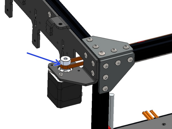
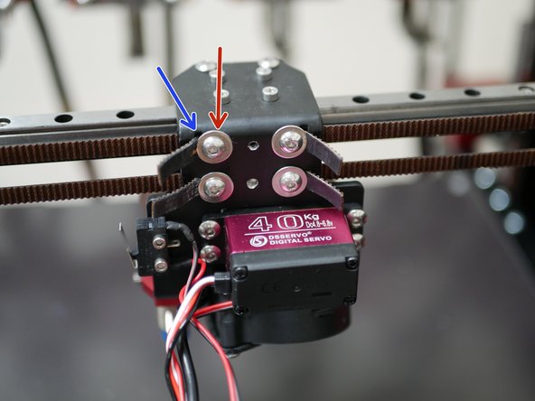
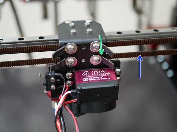
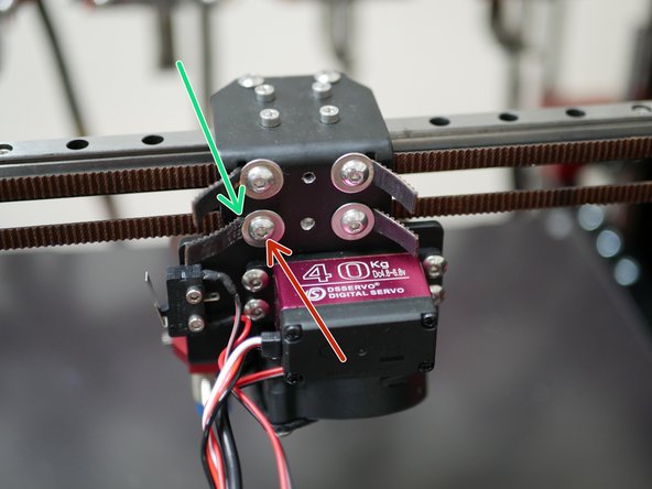
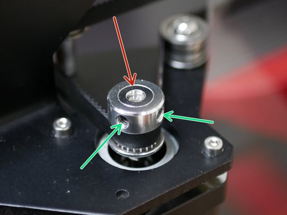
With the belts tensioned manually move the tool carriage around to allow the pulley heights to settle into position.
-
The ideal position for all of the pulleys should be approx 2mm above the end of the motor's shaft.
-
Tighten the set screw against the flat of the motor shaft.
-
-
-
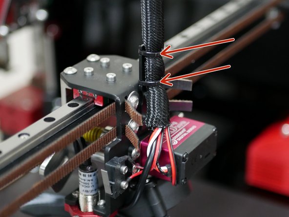
Install the cable relief bracket to the carriage with two M3 x 6mm Bolts.
-
-
-
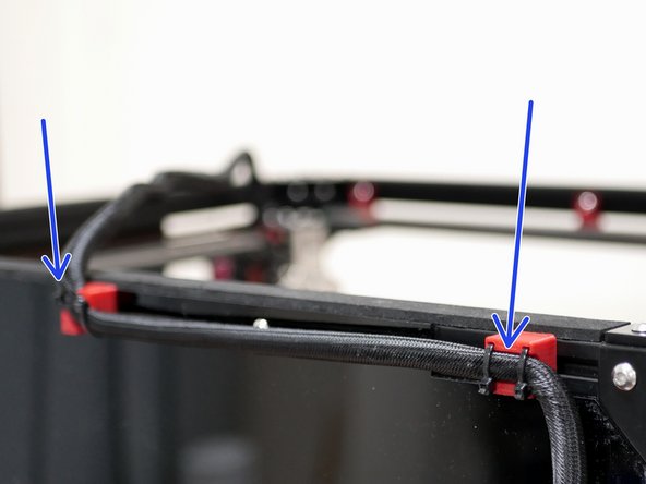
Mount to the rear top of the frame the two 3d printed cables brackets.
-
3D Printed Cable Guide
-
3D Printed Cable Guide - Right Angle
-
M5 x 8mm Button Bolt
-
M5 T-nut
-
-
-
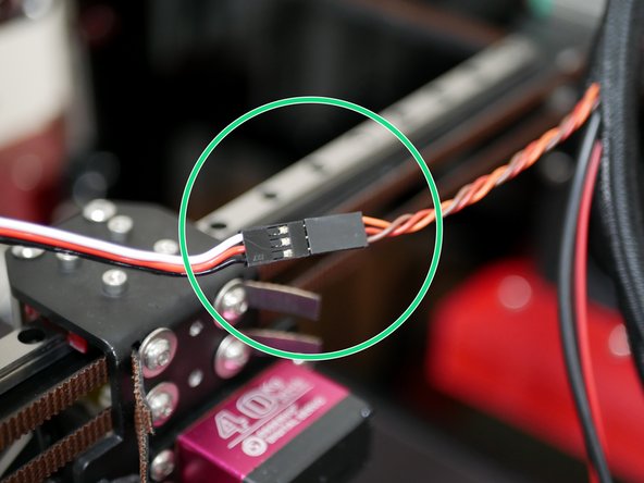
Attach to the servo cable to the servo extension cable.
-
An earlier batch of extension cables came with the wrong connector, it should be male but is female. An adapter cable was later shipped in order to make this connection.
-
Adapter colours shouldn't matter - the extension cable and servo cable should have orange match with white and brown match with black, as shown in the image.
-
-
-
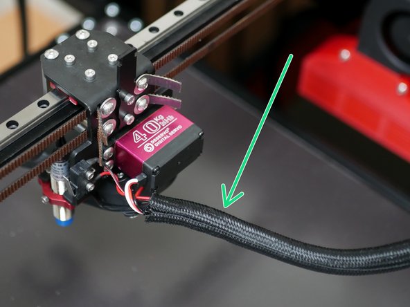
Take the remaining braided sleeving that you cut the sleeving of the heated bed cables from and use it to wrap the tool changer carriage cables.
-
Use cable ties to fix the cable loom to the bracket.
-
-
-
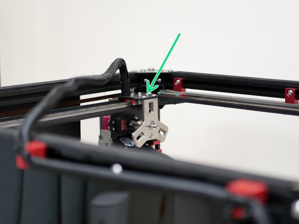
Move the tool head to the bottom right as shown.
-
Use cable ties to secure the cable loom to the back of the frame.
-
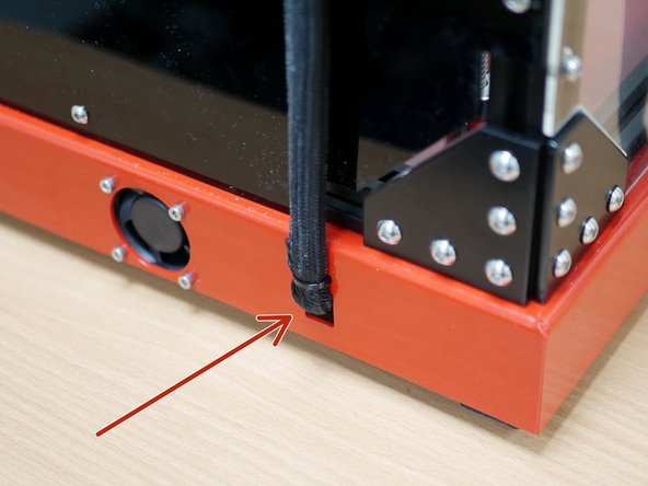
Feed the cables into the base using a cable tie to hold it in place.
-


Cancel: I did not complete this guide.
18 other people completed this guide.

2 Comments
***Step 41*** Servo Extension Cable - I found that my extension cable has different colours than whats in the picture. Needless to say look at the way the two cables meet in the picture. One has the silver prongs showing, and the other doesn't. Follow that and it worked for me.