-
-
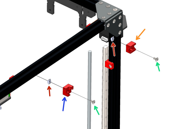
Prepare 6 rail mounts as shown by loosely fastening an M5 T-nut onto the M5 bolt.
-
M5 x 8mm Bolt
-
M5 T-nut
-
-
-
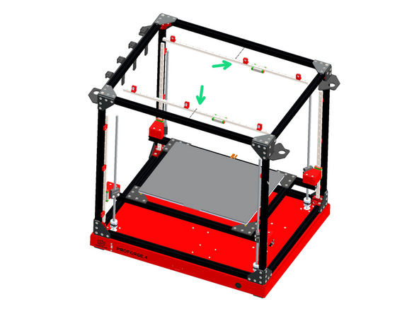
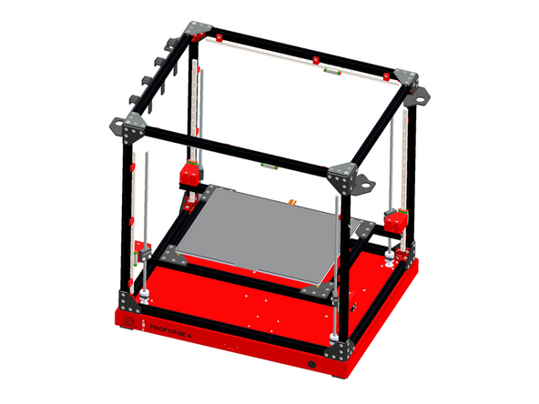
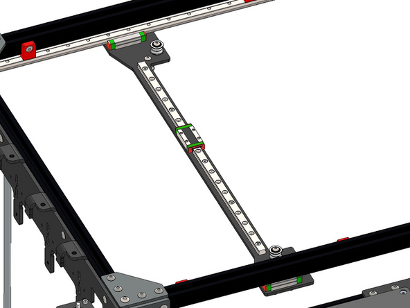
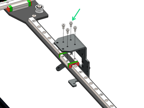
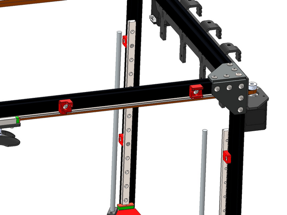
Fix the rail mount assemblies from the previous steps onto the two 550mm long MGN12 rails.
-
Space them out as shown with two fixed one from the edge and the third in roughly the centre.
-
M3 x 6mm Cap Bolt
-
Use the orange stoppers to prevent the carriage from falling off the rail. It is important to not let it fall of as this could cause the small ball bearings to fall out of the carriage.
-
-
-
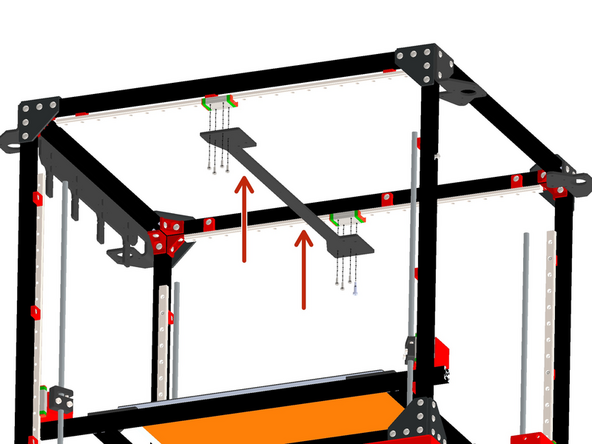
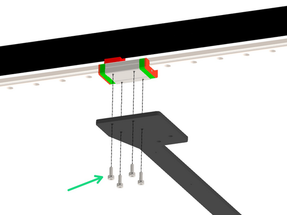
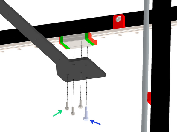
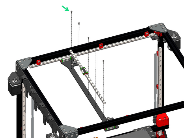
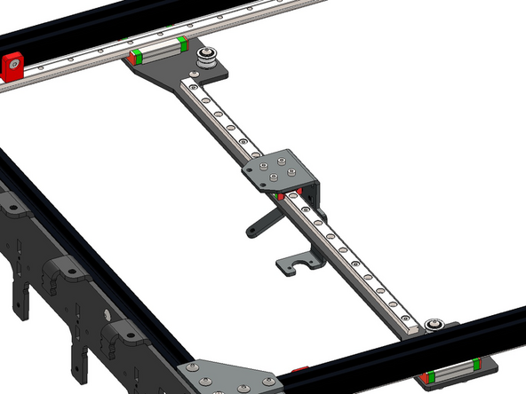
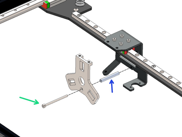
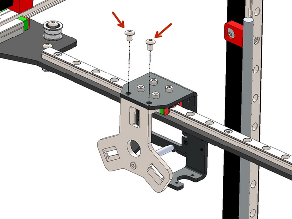
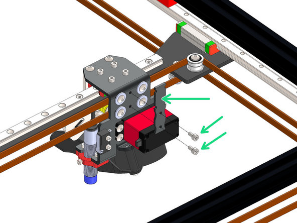
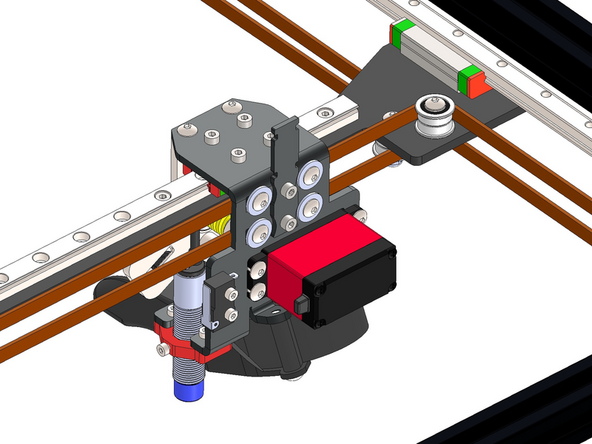
Mount the gantry panel onto the carriages.
-
M3 x 8mm Cap
-
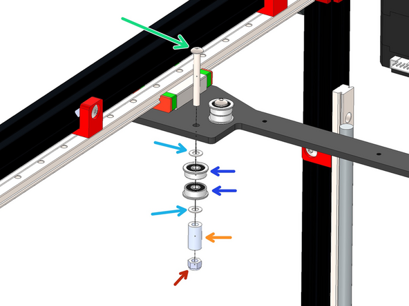
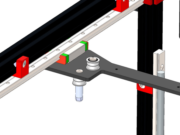
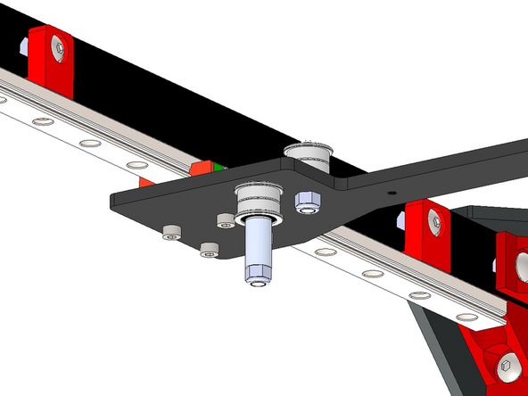
M3 x 10 x 6 Sholder Bolt
-
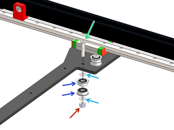
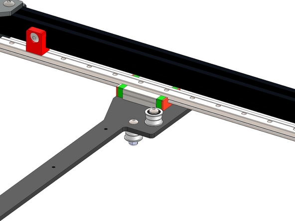
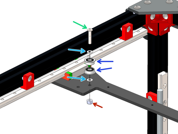
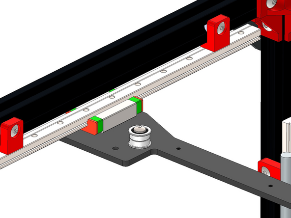
Match the orientation of the gantry bracket as shown.
also, this is a good time to install all gantry panel idlers if you don't want to contort yourself later.
to ensure that the gantry panel is fastened perpendicular to rails:
- move both carriages onto the extreme ends of the rails
- lightly fasten the gantry panel to the side with the shoulder nut. this will be the anchor point, since the other side has oval slots to accommodate some degree of adjustment
- lightly fasten the non-shoulder side of the gantry to its carriage
- slide the gantry panel to the other extreme end of the rail, ensuring that both sides of the gantry panel contact the orange stoppers/frame
- tighten all fasteners on the gantry panel
- slide the gantry back to the other extreme position on the rail, and ensure that it also contacts the orange stoppers/frame, with no resistance along the way.
-re-tighten gantry panel fasteners if required
-
-
-
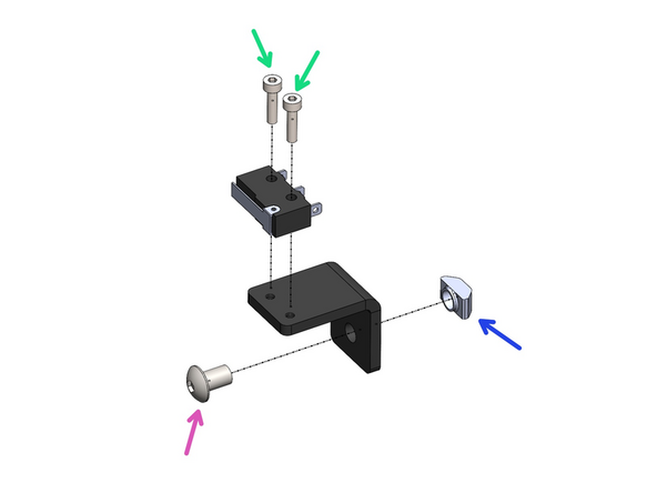
Assemble an endstop to the X-Endstop Bracket.
-
M2.5 x 10mm Cap
-
Loosely fasten on an M5 bolt and T-nut
-
M5 x 8mm
-
M5 T-nut
The X-Endstop would not click if I fully moved the gantry all the way to the right.
So I printed out a 2mm thick washer and then used a M5*10 screw, re-assembled the X-Endstop Bracket and I now hear a nice clicking noise just before the gantry goes all the way to the right.
Richard Thomas - Resolved on Release Reply
The end stop switches have long wires attached. Initially I was looking for just the limit switch. Also, there are two of them. Grab one.
Paul Platt - Resolved on Release Reply
If M2.5 x 10mm is what's included then surely you should change the text, rather than leaving us to (eventually) notice in the comments?
Mark Wheadon - Resolved on Release Reply
-
-
-
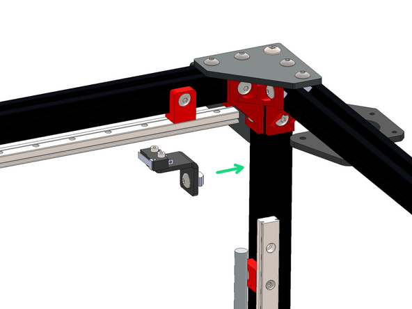
Mount the X-Endstop Assembly to the inside of the frame on the rear right side.
-
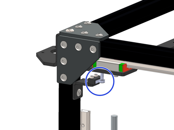
Align the endstop switch with the shoulder bolt on the gantry - It should trigger the endstop when the gantry is moved all the way to the right.
This requires removing the orange stoppers at the end of the rails. Otherwise, the shoulder bolt won’t reach the limit switch.
Paul Platt - Resolved on Release Reply
-
-
-
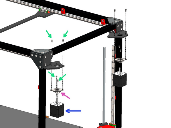
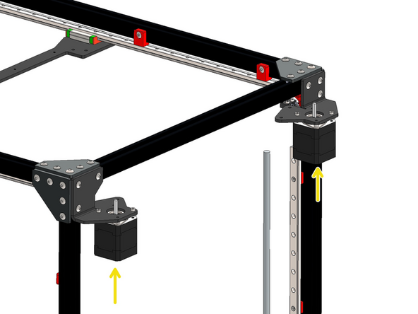
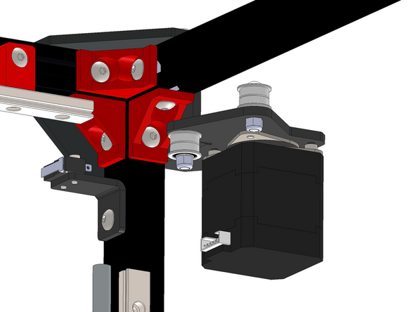
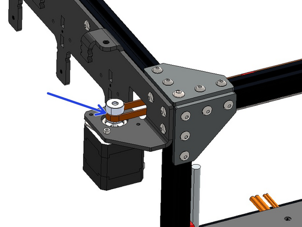
Install the LDO motors to the frame with the motor dampeners.
-
M3 x 6mm Cap Bolt
-
Motor Dampener
-
LDO NEMA 17 Motor
-
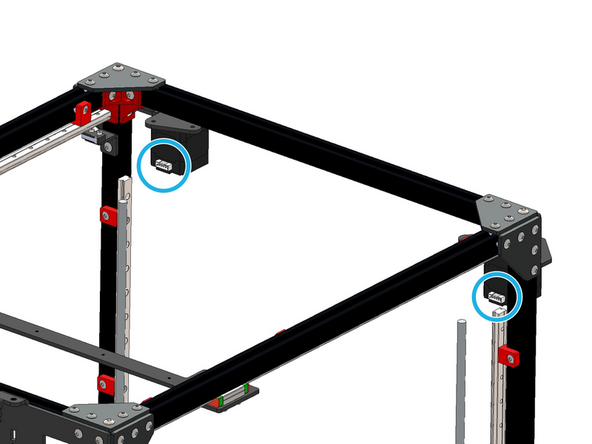
Install the motor so that the cable connector faces inwards.
-
Finally add the heatsinks to the underside of the motors.
-
Use the cables that came with the LDO motors with the LDO motors and NOT the BIQU Z-motors. We recommend placing these cables back into the LDO box until the wiring stage.
I'm assuming those heatsinks stick on the end of the stepper, so over the top of the back end of the axle? @makertech3d could you confirm please, and perhaps update the text?
Mark Wheadon - Resolved on Release Reply
This is the all important step where you realize you used the wrong set of steppers on the base. Sigh.
Brian Mettlen - Resolved on Release Reply
-
-
-
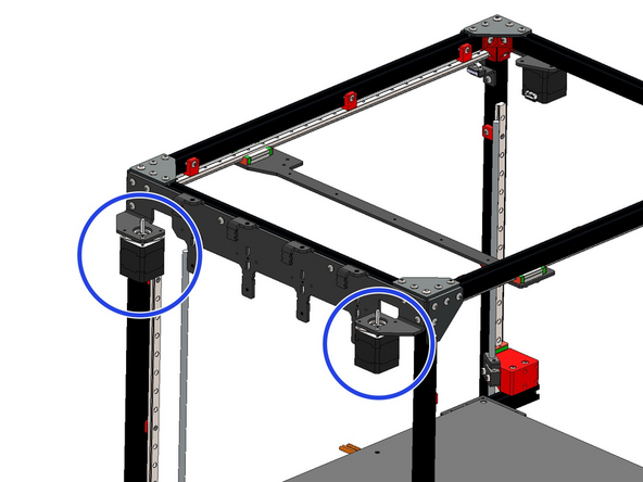
Repeat the process for the motors on the other side of the frame.
-
Again, it's very important to use the cables that came with the LDO motors with the LDO motors and NOT the BIQU Z-motors. We recommend placing these cables back into the LDO box until the wiring step.
-
-
-
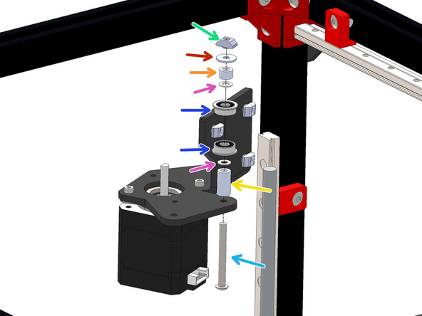
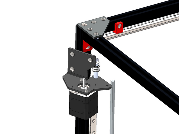
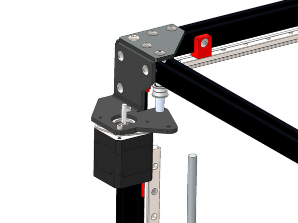
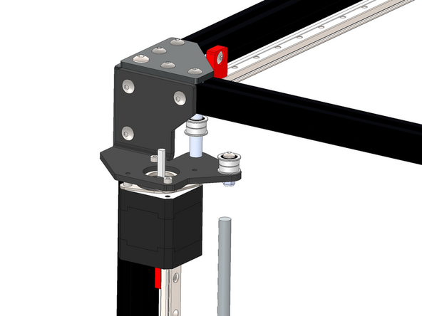
You will need to unmount the bracket to gain access for assembling this idler stack, re-mount it to the frame after building the Idler stack by also fixing the M4 x 40mm bolt to the top extrusion.
-
M4 T-nut
-
M4 Penny Washer
-
M4 x 5mm Spacer
-
M4 x 8 x 0.5mm Shim
-
F624ZZ Bearing
-
M4 x 15mm Spacer
-
M4 x 40mm Button bolt
-
-
-
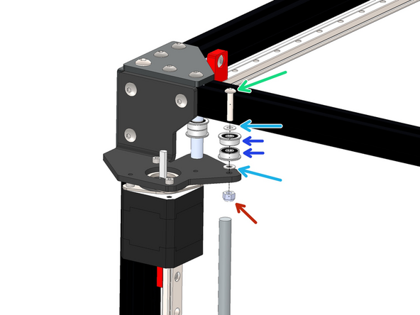
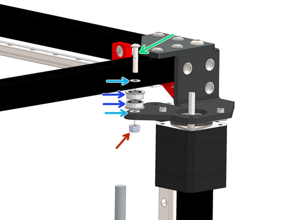
Assemble the second idler stack to the same front right motor bracket as shown.
-
M4 x 20mm Button
-
M4 x 8 x 0.5mm Shim
-
F624ZZ Bearing
-
M4 Nyloc Nut
-
-
-
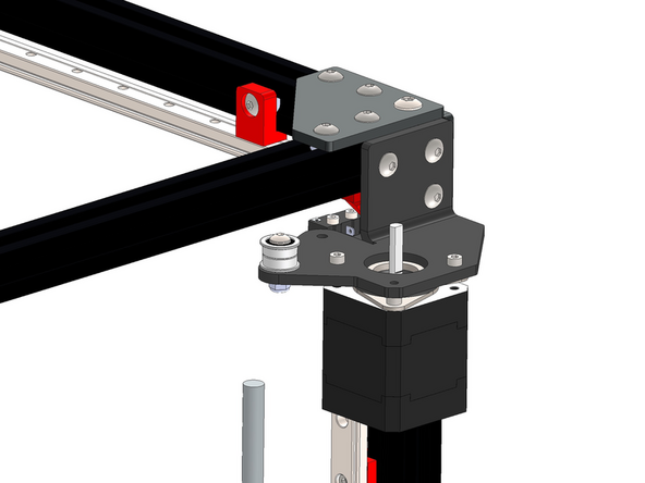
Assemble the Idler stack to the rear right motor bracket as shown.
-
M4 x 20mm Button Bolt
-
M4 x 8 x 0.5mm Shim
-
F624ZZ Bearing
-
M4 Nyloc Nut
-
-
-
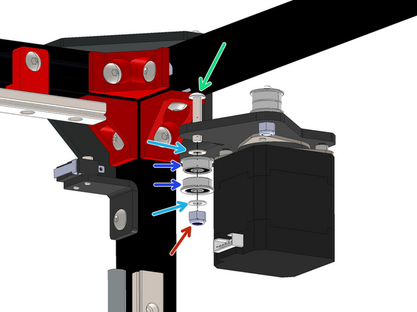
Install the second Idler stack to the rear right motor bracket as shown.
-
M4 x 20mm Button bolt
-
M4 x 8 x 0.5mm Shim
-
F624ZZ Bearing
-
M4 Nyloc Nut
If you slide the bolt toward the corner and parallel to the top rail, it will just fit.
Chris Urban - Resolved on Release Reply
How does this bolt go in? There isn’t enough distance between the bracket with the hole and the rail.
Paul Platt - Resolved on Release Reply
-
-
-
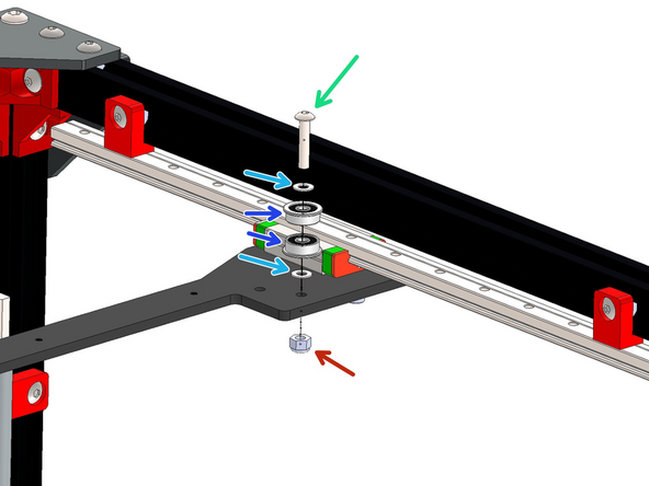
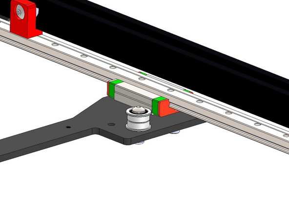
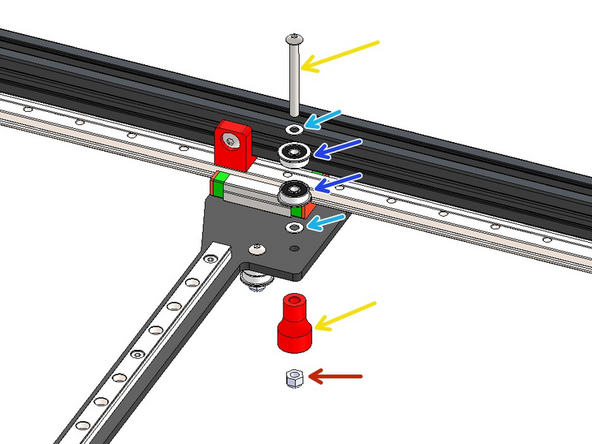
Build the Idler stack as shown on the far side of the gantry bracket.
-
M4 x 20mm Button Bolt
-
M4 x 8 x 0.5 mm Shim
-
F624ZZ Bearing
-
M4 Nyloc Nut
-
If you're building v4.2 use an M4 x 40mm bolt and add the 3d printed endstop trigger.
-
-
-
Build the second Idler stack as shown on the far side of the gantry bracket.
-
M4 x 20mm Button Bolt
-
M4 x 8 x 0.5mm Shim
-
F624ZZ Bearing
-
M4 Nyloc Nut
-
-
-
Build the third Idler stack as shown on the near side of the gantry bracket.
-
M4 x 20mm Button Bolt
-
M4 x 8 x 0.5mm Shim
-
F624ZZ Bearing
-
M4 Nyloc Nut
-
-
-
Build the fourth Idler stack as shown on the near side of the gantry bracket.
-
M4 x 35mm Button Bolt
-
M4 x 8 x 0.5mm Shim
-
F624ZZ Bearing
-
M4 x 15mm Spacer
-
M4 Nyloc Nut
-
-
-
Mount the MGN9 rail onto the gantry.
-
M3 x 8mm Cap Bolt
-
Take care to not let the carriage fall of the rail. Use the orange stoppers for this.
-
-
-
Fix the Tool Changer Bracket onto the rail carriage.
-
M3 x 6mm Cap Bolt
-
-
-
Fix the Master Plate onto the tool changer bracket.
-
M3 x 45mm Cap Bolt
-
3mm x 35mm Spacer
-
M4 x 6mm Button
I can’t find the 4x6 button bolts. I have taken two from the parts for one of the extruders. I hope I can get some before I need them.
Paul Platt - Resolved on Release Reply
-
-
-
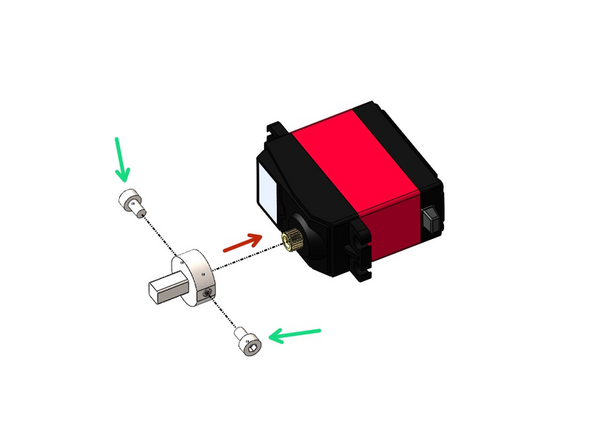
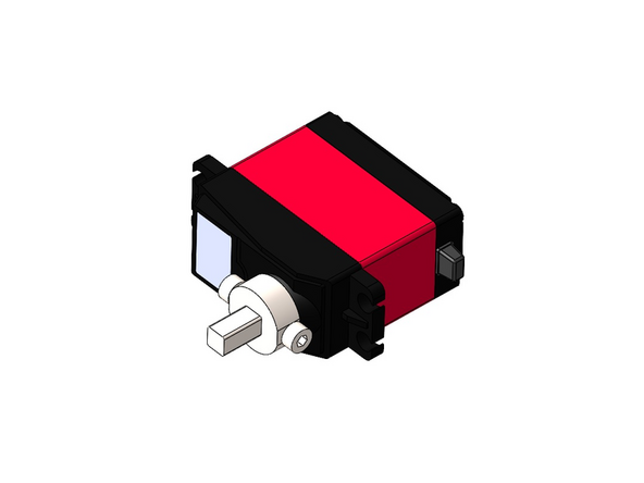
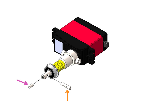
Loosely fix on two M3 x 5mm bolts to the Tool Changer Drive Shaft
-
Then slide it onto the servo motor
-
-
-
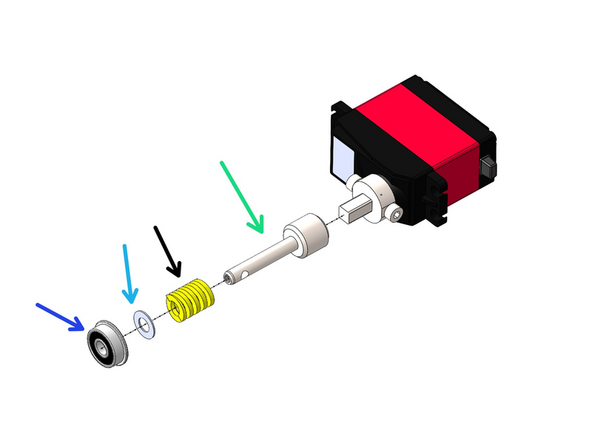
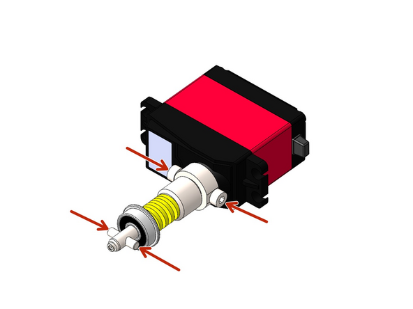
Build the Tool Changer Mechanism as shown
-
Tool Changer - Cam Shaft
-
Spring
-
M5 x 10 x 0.5mm Shim
-
F605ZZ Bearing
-
Cam Pin
-
M3 x 4mm Grub Screw - Tighten the grub screw against the flat side of the cam pin.
-
Make sure the cam pin is aligned with the bolts on the drive shaft.
-
-
-
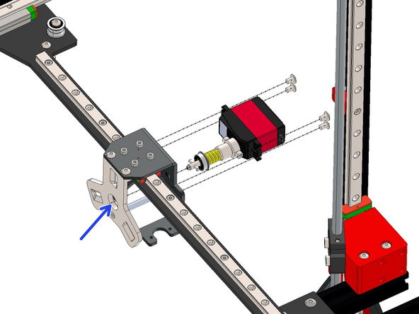
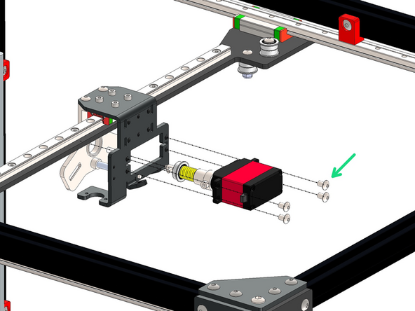
Slide the assembly in through the rear of the carriage bracket and into the hole on the master plate as shown.
-
Fix the servo in place with four M4 x 6mm Bolts
It's not clear whether the two M3 x 5mm bolts holding the Tool Changer Drive Shaft are still meant to be loose. I've left them slack so that when the servo powers up it can find its position before I tighten up those bolts.
Mark Wheadon - Resolved on Release Reply
Yes, don't tighten these bolts just yet - they are tightened later when up and running.
-
-
-
Fix the 50mm blower fan to the tool changer assembly.
-
M4 x 25mm Button
-
3D Printed Fan Shroud
-
50mm Blower Fan
-
Do not over tighten, the shroud is 3d printed and could snap.
Don't over-torque the bolts as that fan case is only so strong.
Mark Wheadon - Resolved on Release Reply
-
-
-
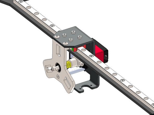
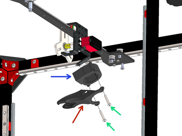
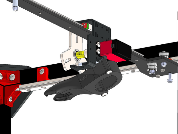
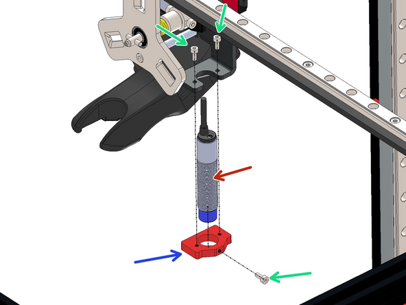
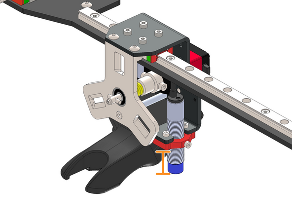
Install the probe by sliding it into the probe mount.
-
Then fix the assembly to the bracket.
-
M2.5 x 6mm Bolt (x3)
-
Approx. 25mm
-
The position of the probe will be adjusted later.
The hole in the mounting bracket for the prox is way too sloppy for my liking. I understand why it wasn't threaded so you don't have to twist up the cable when making adjustments but it could have been more of a clearance fit. I added one of the nuts that came with the proxy to the bottom to help square it up more securely.
In which step do we adjust the probe position? I can't find it.
-
-
-
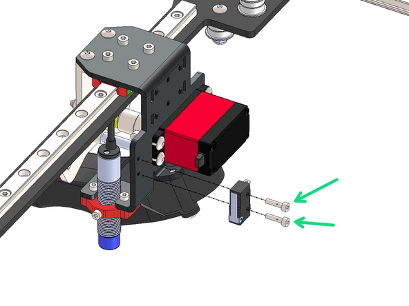
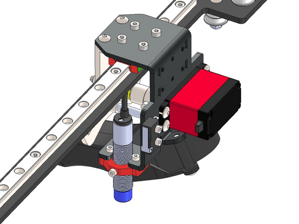
Fix the endstop onto the carriage with two M2.5 x 10mm bolts.
-
-
-
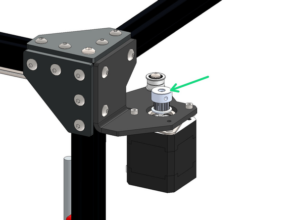
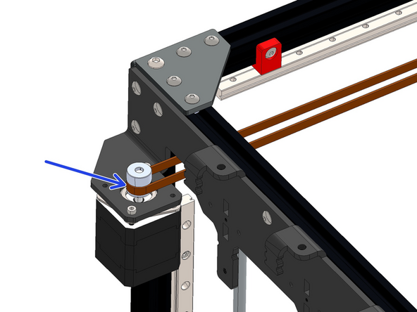
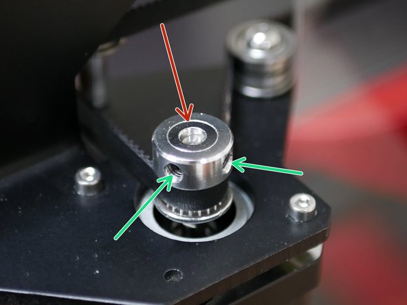
Drop pulleys onto each of the four motors.
-
Orientate so that the pulley teeth are facing downwards.
-
Do not tighten yet.
-
-
-
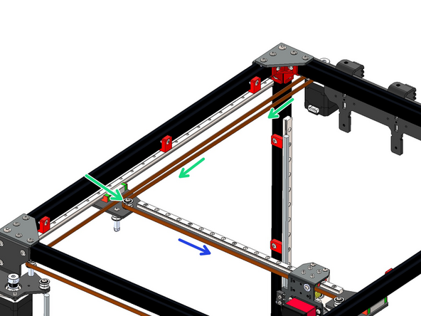
Take the 5m roll of GT2 belt and cut it in half.
-
Aim to get both halves as equal in length as possible.
-
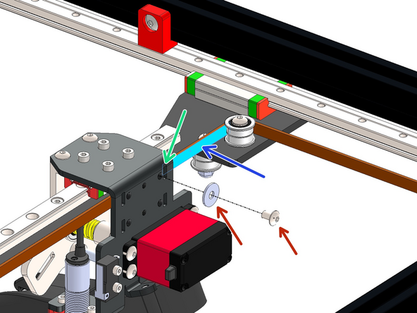
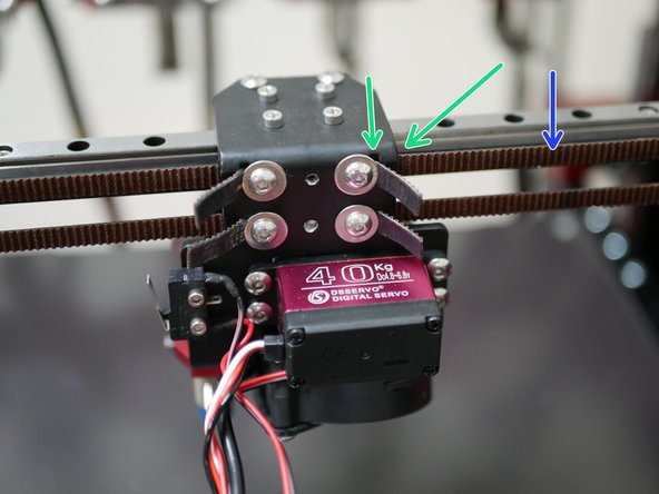
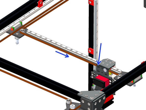
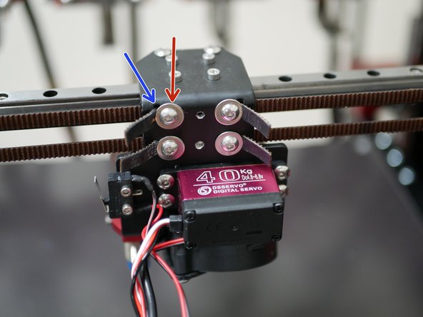
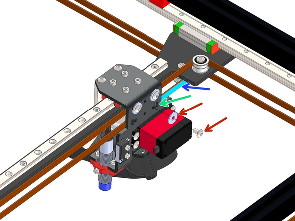
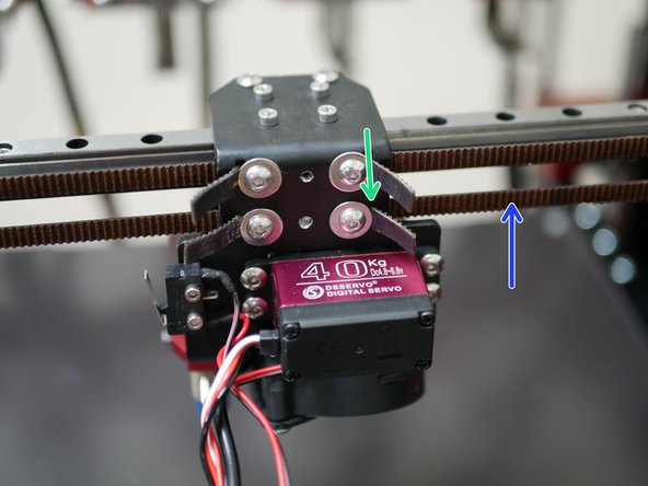
Take an end of one of the belts and feed it in through the top right slit on the back of the carriage bracket.
-
It needs to be fed in from the inside of the bracket - you will need to temporarily remove the bracket from the linear rail carriage to gain better access.
-
Ensure that the belts teeth are facing out.
-
Fix the belt in place with an M4 x 6mm bolt and M4 penny washer.
A hook style needle nose tweezer works well to push the belt through slot without removing the bracket from the linear rail.
Pete Pubben - Resolved on Release Reply
-
-
-
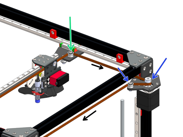
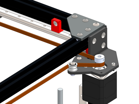
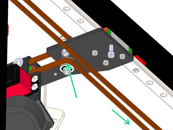
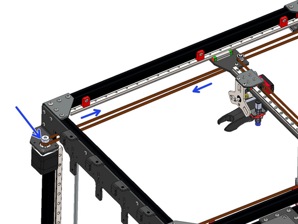
Wrap the belt around the idler on the gantry.
-
Next feed it around the pulley on the rear right motor's pulley and idler.
-
-
-
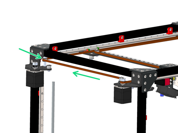
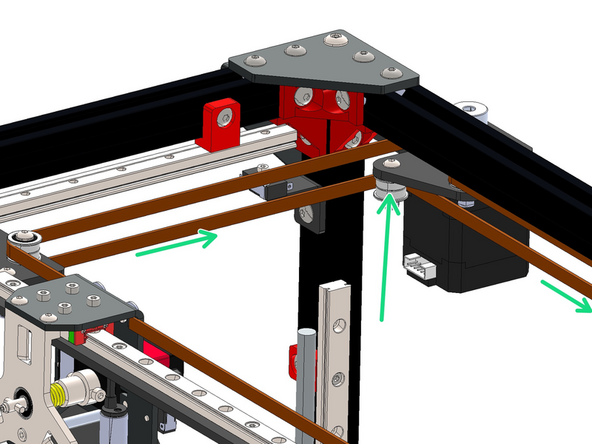
Next feed the belt across the top and to the idler on the other motor bracket.
-
-
-
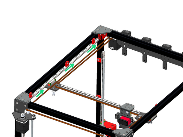
Next feed the belt down the long side of the frame going over the gantry bracket.
-
Wrap the belt around the front left motor's pulley.
Over the gantry (i.e. not under it). (Don't know whether this is obvious enough that I shouldn't comment.)
Mark Wheadon - Resolved on Release Reply
-
-
-
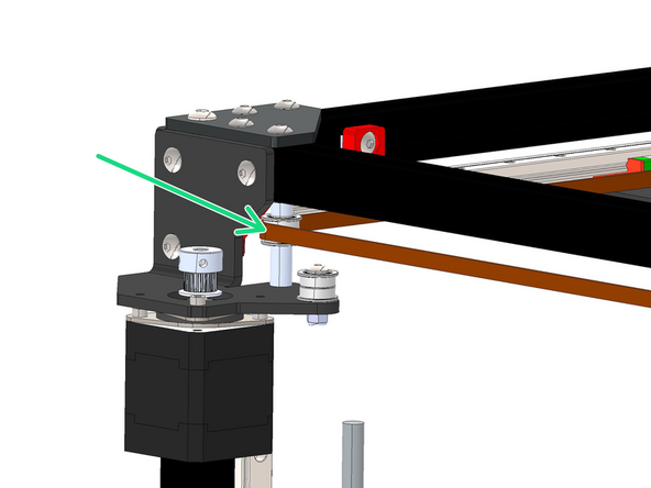
Feed the belt back down the long side of the frame and around the pulley on the gantry bracket.
-
Fix the end of the belt into the slot on the top left of the bracket - again feeding it in from the inside of the bracket.
-
Secure the belt with an M4 x 6mm bolt and M4 penny washer - do not fully tighten down this bolt yet, as we will be tensioning this belt later.
-
-
-
Take an end of one of the belts and feed it in through the slit on the back of the carriage bracket.
-
Again, it needs to be fed in from the inside of the bracket - you may need to temporarily remove it from the linear rail carriage to gain better access.
-
Ensure that the belts teeth are facing out.
-
Fix the belt in place with an M4 x 6mm bolt and M4 penny washer.
-
-
-
Start by wrapping the belt around the idler on the underside of the gantry bracket.
-
Next feed it around the pulley on the rear left motor.
-
-
-
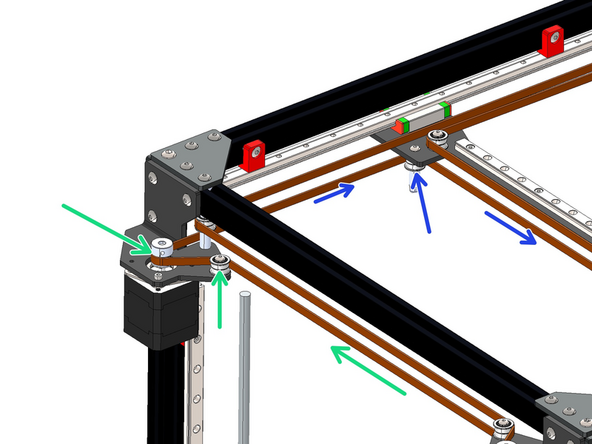
Feed the belt down the long side of the frame and wrap it around the idler on the rear right side motor bracket.
-
-
-
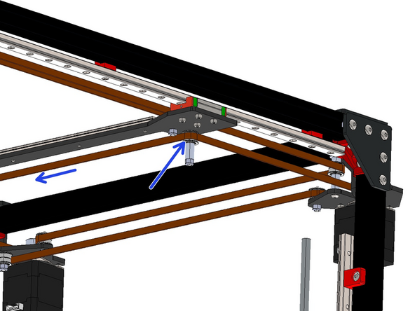
Feed the belt around the idler and pulley on the front right motor bracket.
-
Next feed the belt around the idler on the bottom of the gantry.
This is a good time to double check that the M3 x 6mm Cap Bolts and Dampeners you installed back in step 7 are positioned the right way so as not to rub the belt.
Chris Urban - Resolved on Release Reply
-
-
-
Finally feed the end of the belt into the slot on the bottom left of the bracket - again feeding it in from the inside of the bracket.
-
Secure the belt with an M4 x 6mm bolt and M4 penny washer - do not fully tighten down this bolt yet, as we will be tensioning the belts in the next step.
-
-
-
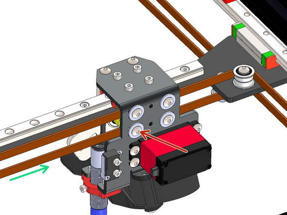
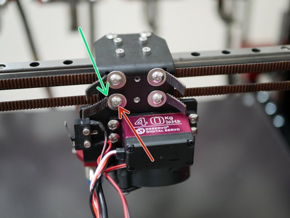
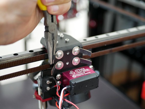
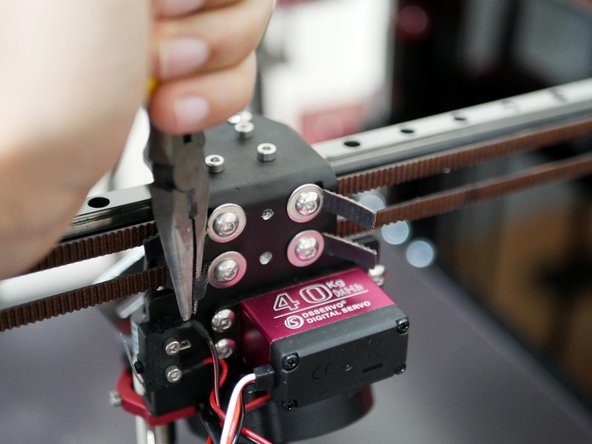
Use the included pair of plies to tension the belts.
-
Loosen these bolts enough to be able to pull the belt with the pliers but also hold the tension without letting the belts slip back.
-
Tension the belts as equally as possible.
-
Tension both belts until they are guitar string tight. Avoid over tensioning as this can put unnecessary strain on the motor shafts.
-
Trim any excess, leaving approx. an inch free for any future adjustments.
The iPhone app I haven’t figured out. The Prusa site sort of works. I am around 100 Hz. The carriage is now very difficult to move. I think it is because all of the tension is on the right side of the carriage. Is this normal?
Paul Platt - Resolved on Release Reply
for anyone else wondering what "guitar tight" means - don't, this is a pretty vague definition that won't help you get proper belt tension.
instead, refer to the voron documentation (applicable to other coreXY printers like the PF4), which gives more detailed instructions + real, numerical values which you can target: https://docs.vorondesign.com/tuning/seco...
I would also recommend this app, its very easy to use compared to other I could find.
-
-
-
With the belts tensioned manually move the tool carriage around to allow the pulley heights to settle into position.
-
The ideal position for all of the pulleys should be approx 2mm above the end of the motor's shaft.
-
Tighten the set screw against the flat of the motor shaft.
-
-
-
Install the cable relief bracket to the carriage with two M3 x 6mm Bolts.
-
-
-
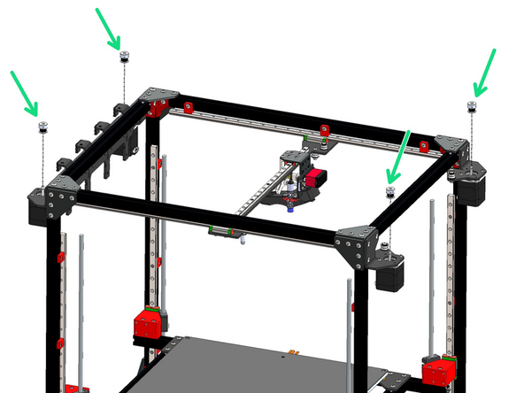
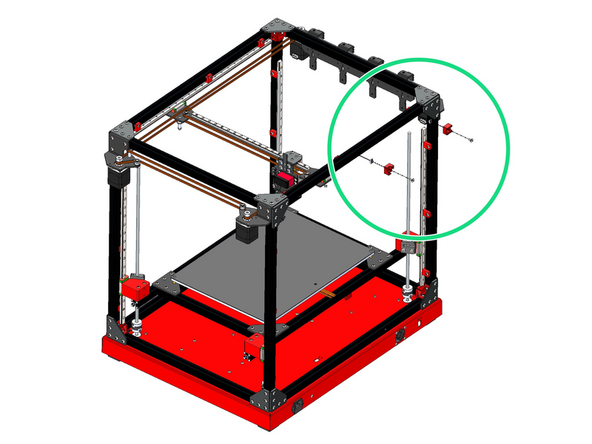
Mount to the rear top of the frame the two 3d printed cables brackets.
-
3D Printed Cable Guide
-
3D Printed Cable Guide - Right Angle
-
M5 x 8mm Button Bolt
-
M5 T-nut
-
-
-
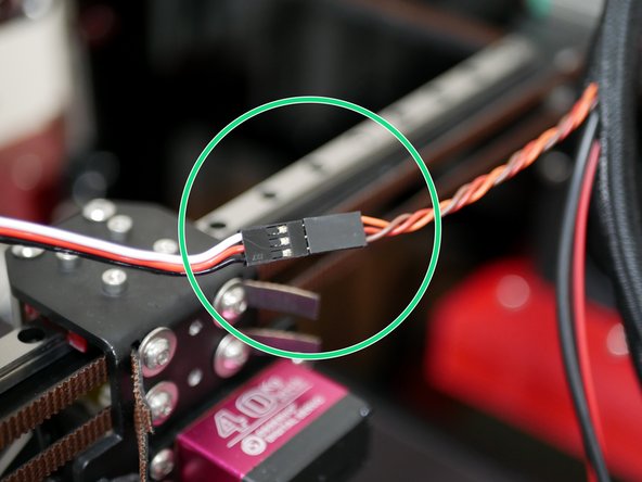
Attach to the servo cable to the servo extension cable.
-
An earlier batch of extension cables came with the wrong connector, it should be male but is female. An adapter cable was later shipped in order to make this connection.
-
Adapter colours shouldn't matter - the extension cable and servo cable should have orange match with white and brown match with black, as shown in the image.
I just realized that the adapter and the extension are two different cables.
Paul Platt - Resolved on Release Reply
The colors on my adapter cable are green-white-orange. The middle wire is white. That makes for green to brown, white to orange and orange to yellow. Does this work?
Paul Platt - Resolved on Release Reply
The servo wires are one set of colors, the adapter has a second set of colors and the extension cable has a third set of colors. The connectors are not keyed so which way do they get connected together? Please provide a picture of the completed cable assembly showing how the adapter is connected to the other two cables.
Dane Weber - Resolved on Release Reply
-
-
-
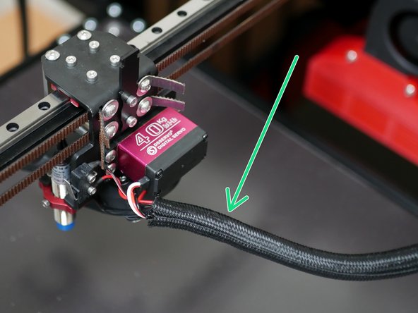
Take the remaining braided sleeving that you cut the sleeving of the heated bed cables from and use it to wrap the tool changer carriage cables.
-
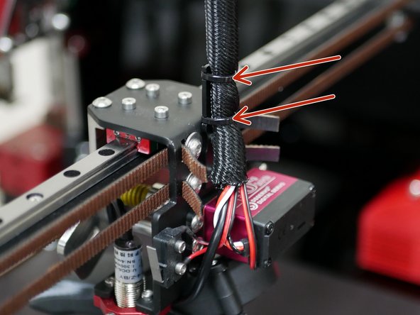
Use cable ties to fix the cable loom to the bracket.
-
-
-
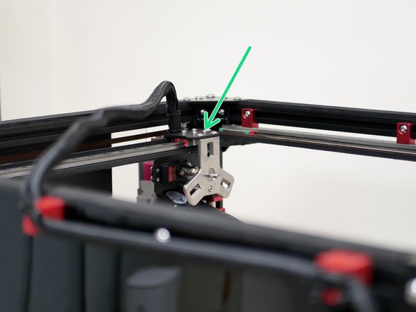
Move the tool head to the bottom right as shown.
-
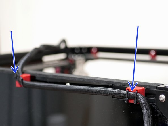
Use cable ties to secure the cable loom to the back of the frame.
-
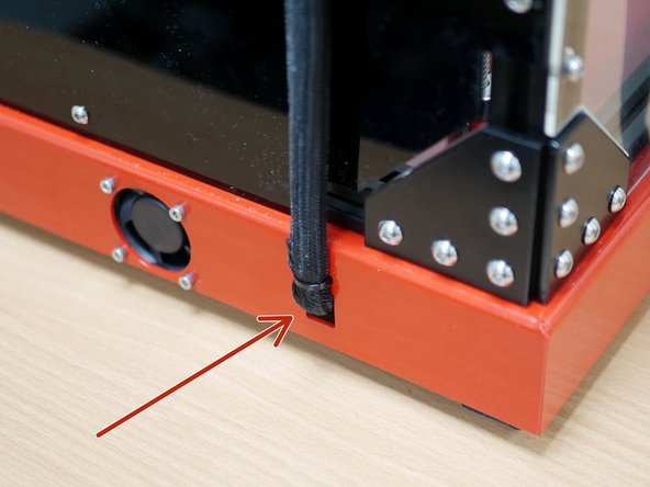
Feed the cables into the base using a cable tie to hold it in place.
as @stefanooo said, my braided sleeve is also much too short. maybe about a foot or so. might need to include another .5 meters in kit.
dan mansfield - Resolved on Release Reply
-
Cancel: I did not complete this guide.
18 other people completed this guide.
2 Comments
***Step 41*** Servo Extension Cable - I found that my extension cable has different colours than whats in the picture. Needless to say look at the way the two cables meet in the picture. One has the silver prongs showing, and the other doesn't. Follow that and it worked for me.



It should also say M5x8 Button
Paul Platt - Resolved on Release Reply
This step of instructions should say 6 rail mounts instead of 12 - a total of 18 are provided, and 12 were already used by the rail mounts for the Platform stage.
Trees - Resolved on Release Reply
Updated, thanks for pointing out.
Makertech 3D -