
-
-
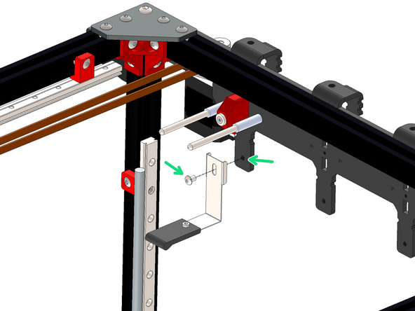
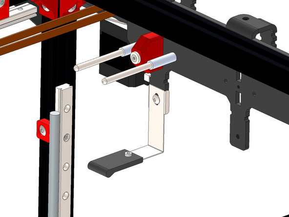
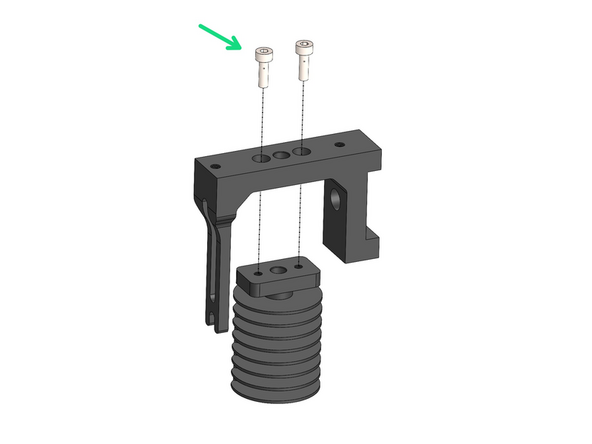
Fix dock pins to tool dock bracket.
-
Dock Pin
-
3 x 25mm Spacer
-
M3 x 35mm Bolt
-
Repeat this across the bracket for the number of print heads you are building.
-
-
-
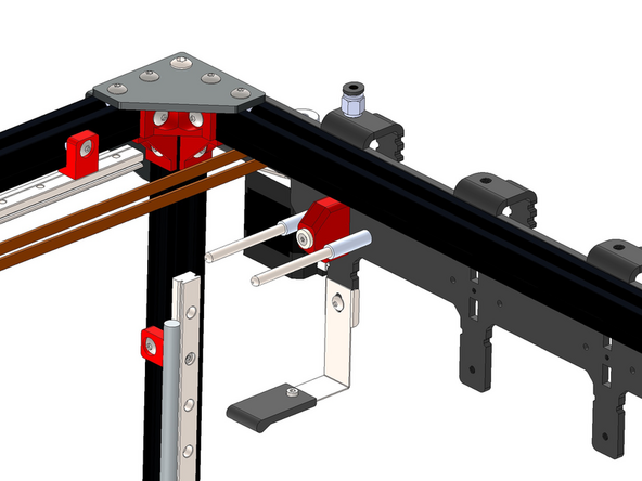
Push the 3d printed dock bracket into the slots on the aluminium bracket.
-
Watch the orientation, the nut holes on the printed part face the back of the printer.
-
Secure it in place with:
-
M3 x 30mm Counter Sunk Bolt
-
M3x10x2mm Countersunk Magnet
-
The magnets are brittle - do not over tighten!
-
Repeat this across the bracket for the number of print heads you are building.
-
-
-
If you have the orbiter filament sensors then you can skip installing these sensors.
-
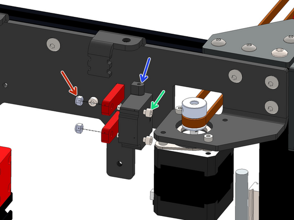
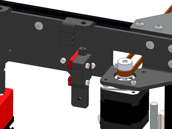
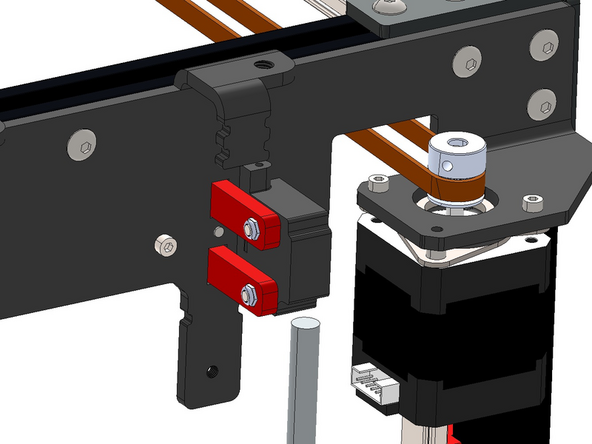
Install the filament sensor to the 3D printed dock bracket.
-
Filament Sensor
-
M3 x 20mm Bolt
-
M3 Nyloc Nut
-
Repeat this across the bracket for the number of print heads you are building that will not be using orbiter filament sensors.
-
-
-
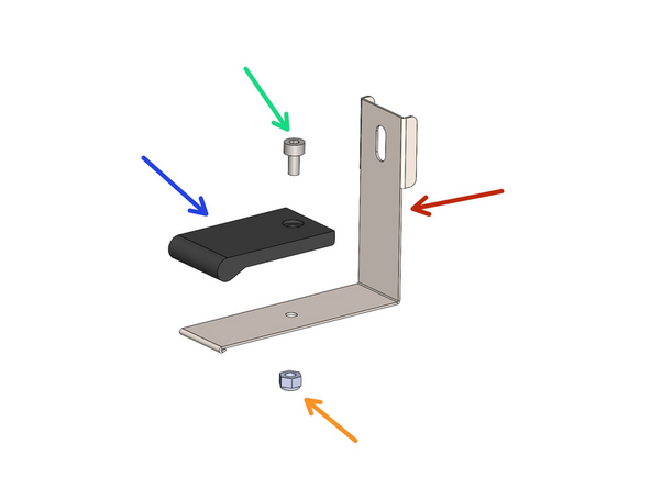
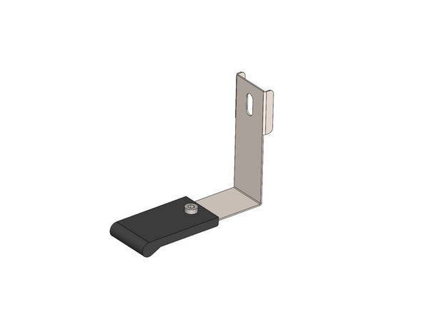
Fix the silicone pad onto the spring steel sled bracket.
-
Spring Steel Sled
-
Silicone Pad
-
M3 x 6mm Bolt
-
M3 Nyloc Nut
-
Repeat this for the number of print heads you are building.
-
-
-
Mount the sled assembly onto the bracket with an M4 x6mm bolt.
-
Repeat this across the bracket for the number of print heads you are building.
-
-
-
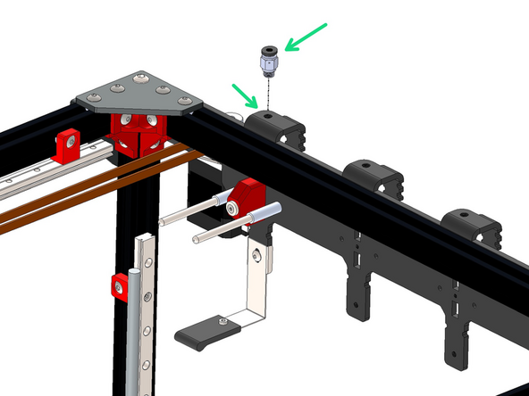
Screw onto the tool dock bracket a PC4-M6 coupling.
-
Repeat this across the bracket for the number of print heads you are building.
-
-
-
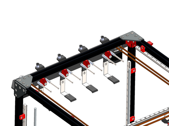
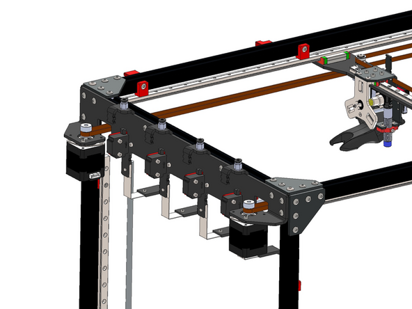
This is what your assembly should now look like if you are building for all four print heads.
-
-
-
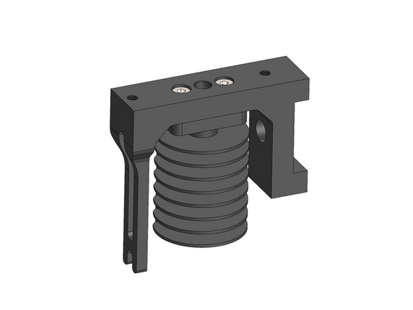
Fix the heat sink core to the heatsink bracket.
-
M2.5mm x 8mm Bolt
-
Match the orientation of the components as shown in the images.
-
Repeat this assembly for the number of print heads you're building.
-
-
-
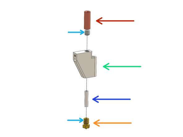
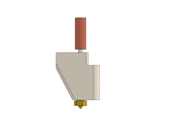
Build the heated block assembly by fastening together the following components.
-
Copper/Titanium Heatbreak
-
Aluminium Heater Block
-
Stainless Steel Spacer - An oversight with the initial batch of kits (pre-2024) meant that these spacers were too short - longer 19mm spacers have now been shipped separately to everyone.
-
Nozzle - This can be of your choosing: Brass/Stainless Steel/Hardened Steel
-
We recommend using PTFE tape to wrap the threads (3-4 turns) to prevent any leaking. PTFE tape was included with the set of hardware sent out later to pre-2024 customers.
-
Tighten as firmly as you can - we will also hot tighten later.
-
Repeat this assembly for the number of print heads you're building.
-
-
-
Drop a heater cartridge into the heater block.
-
Secure in place with two M2.5 x 3mm grub screws.
-
Repeat this assembly for the number of print heads you're building.
-
-
-
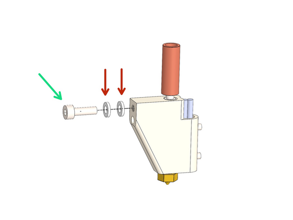
Add to the heater block assembly two ceramic washers.
-
M3 x 10mm Bolt
-
M3 Ceramic Washer
-
Fasten the bolt on by just a few turns, it will be tightened down in the next step.
-
Repeat this for the number of print heads you're building.
-
-
-
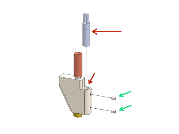
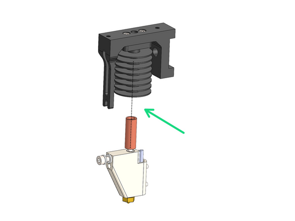
Push the Heater Block Assembly into the Heatsink as shown.
-
The heatsink bracket should fit in-between the two ceramic spacer.
-
Tighten lightly to prevent the ceramic spacer from breaking.
-
Repeat this for the number of print heads you're building.
-
-
-
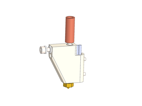
Secure the heater block assembly with two M2.5 x 8mm bolts.
-
Repeat this for the number of print heads you're building.
-
-
-
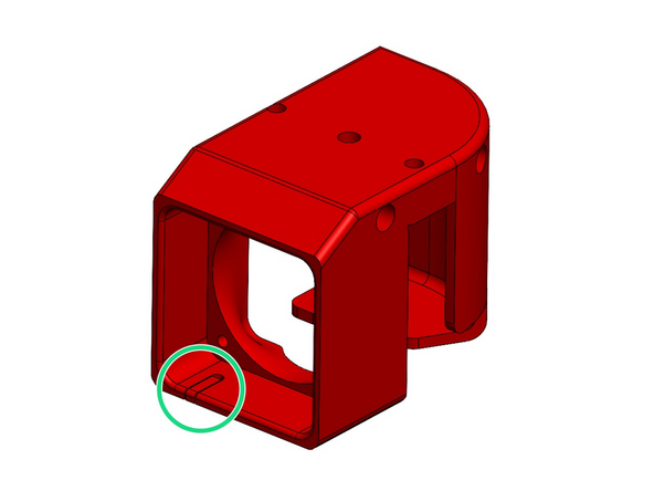
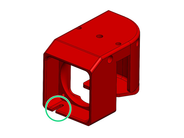
Remove the support material from the 3d printed hotend case.
-
Repeat this for the number of print heads you're building.
-
-
-
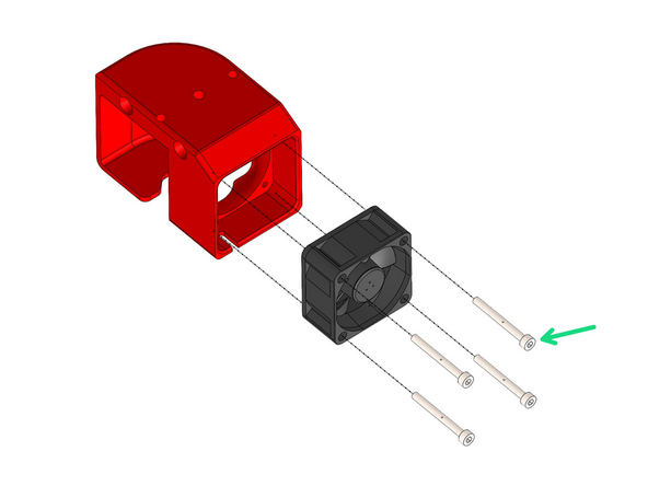
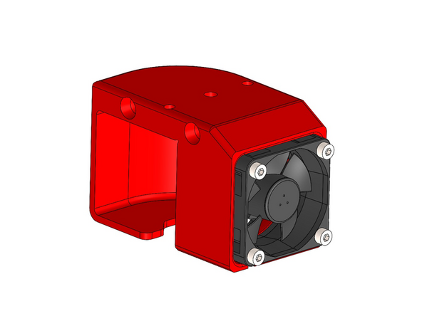
Install the 40mm fan to the 3d printed casing.
-
M3 x 30mm bolt
-
These bolts can be self tapped into the holes on the 3d printed part. Do not over-tighten.
-
The fans cable should pass through the gap that you removed the support material from in the previous step.
-
Repeat this for the number of print heads you're building.
-
-
-
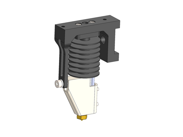
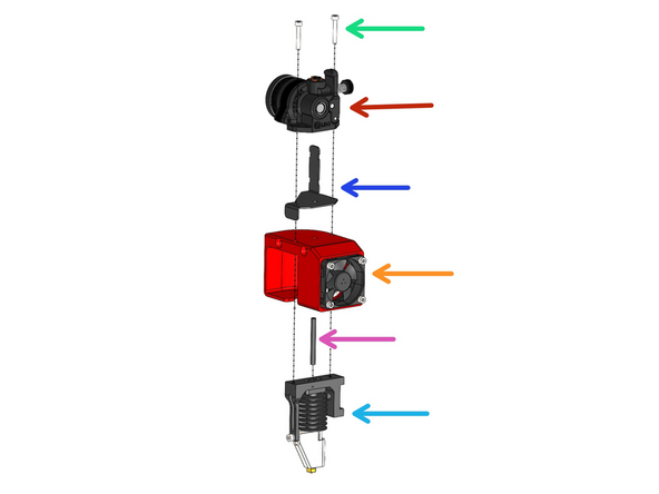
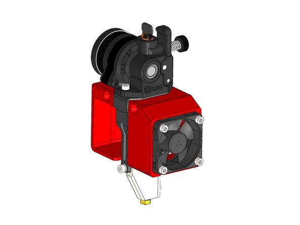
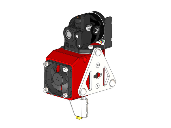
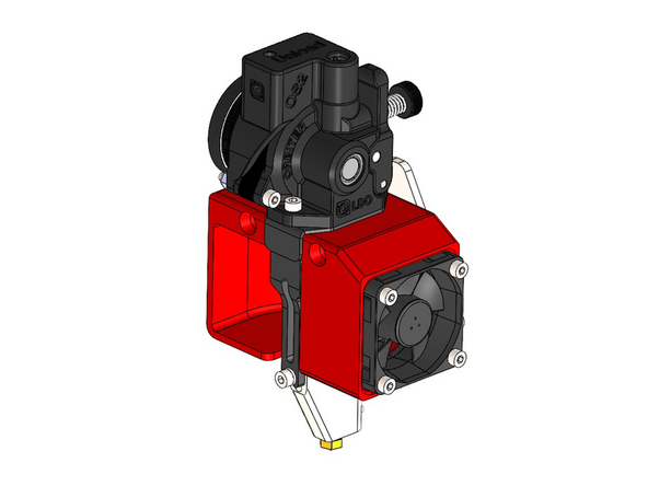
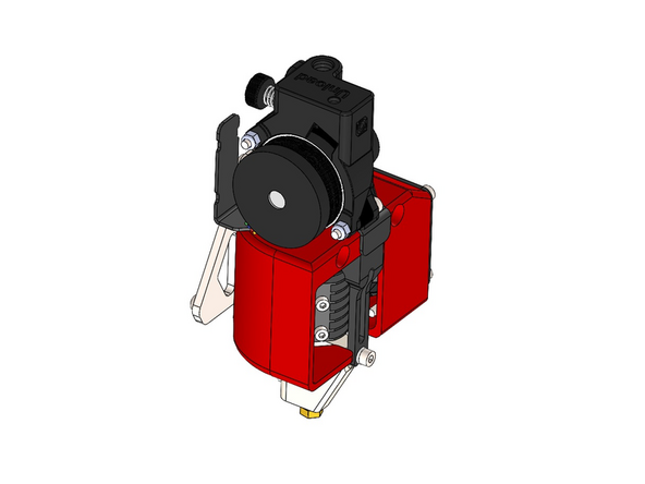
Build the print head assembly as shown by fastening the M3 bolts into the heatsink:
-
M3 x 20mm Bolt
-
Orbiter v2 Extruder
-
Hotend Cable Bracket
-
Fan Assembly
-
PTFE Tubing - 40mm length
-
Hotend Assembly
-
Repeat this for the number of print heads you're building.
-
-
-
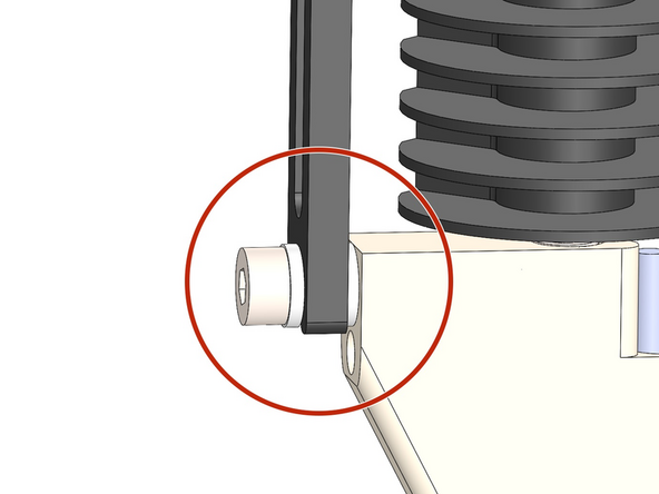
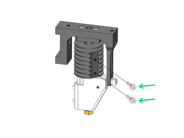
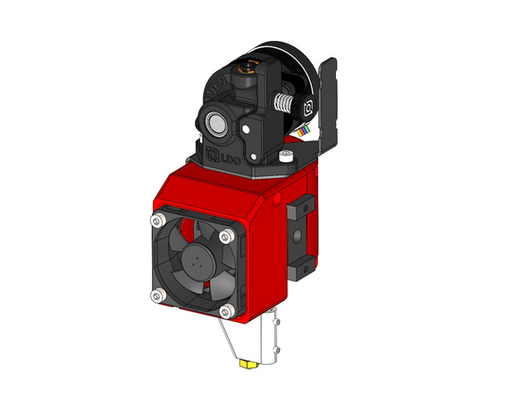
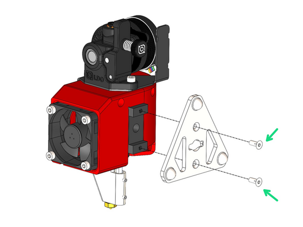
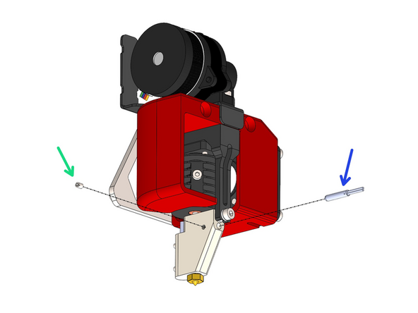
Fix the Tools Plate onto the print head assembly.
-
M3 x 8mm Counter Sunk Bolt
-
Repeat this for the number of print heads you're building.
-
-
-
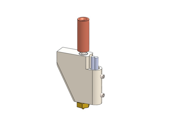
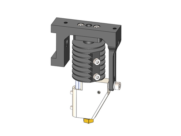
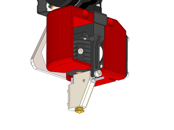
Fix the PT1000 sensor to the heater block.
-
M2.5 x 3mm Grub Screw
-
Repeat this for the number of print heads you're building.
-
-
-
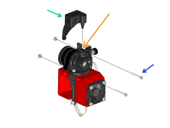
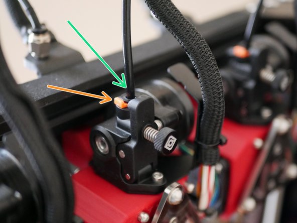
Installing the Orbiter filament sensors will require you to first remove the PTFE coupling from the extruder. Do this by removing the orange clip and pulling on the inserted coupling.
-
Next drop in the sensor.
-
Secure the sensor with the included bolts and nuts.
-
-
-
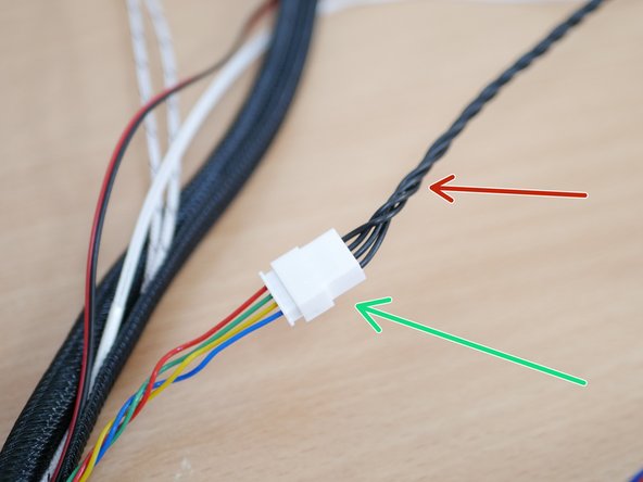
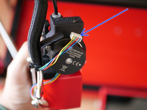
Connect the orbiter extension cable to the end of the orbiter extruders cable.
-
The colours for this cable are red, green, yellow, and blue - not black as shown in the picture.
-
If you have the orbiter filament sensors installed connect its cable to the back of the sensor.
-
-
-
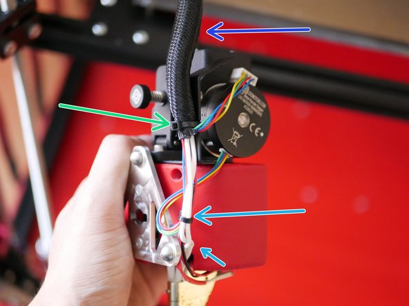
Route the cables from the print head to the rear of the fan case. Use a cable tie to hold them together.
-
Wrap all of the cables from the print head into the braided cable sleeving.
-
Use cable ties to tie it to the bracket as shown.
-
-
-
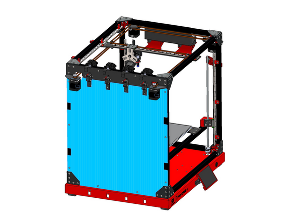
If you plan on installing the enclosure, we recommend installing the left panel at this point before securing the cables form the print heads to the frame.
-
Follow the first two steps from the enclosure install guide here.
-
-
-
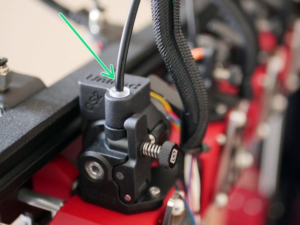
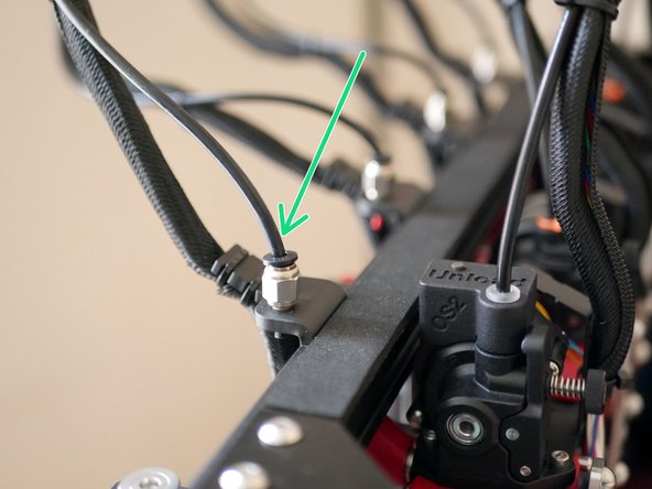
Take the PTFE tube and connect one side to the print head and the other to the coupling on the frame.
-
To fix the tubing to the Orbiter extruder the orange clip needs to first be removed, the PTFE tube inserted and then the orange clip be pushed back on to hold it in place.
-
-
-
Cable supports are now available here. See install guide here.
-
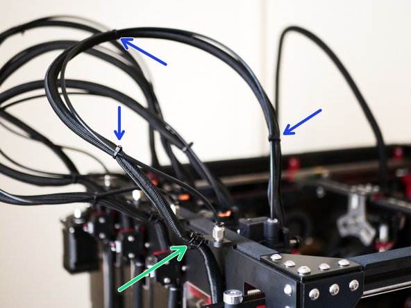
Use cable ties to secure the cable loom to the PTFE tube.
-
If you are running the default filament sensors, connect their cable to them now and feed them into the braided sleeving.
-
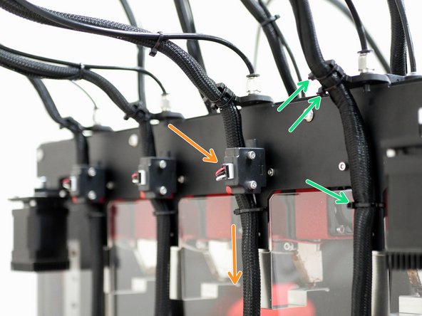
Use cable ties again to fix the cable loom to the frame as shown - in the production version this part of the bracket points down.
-
Make sure that there is still enough slack in the cable that the print head can reach the far corners of the printer.
-
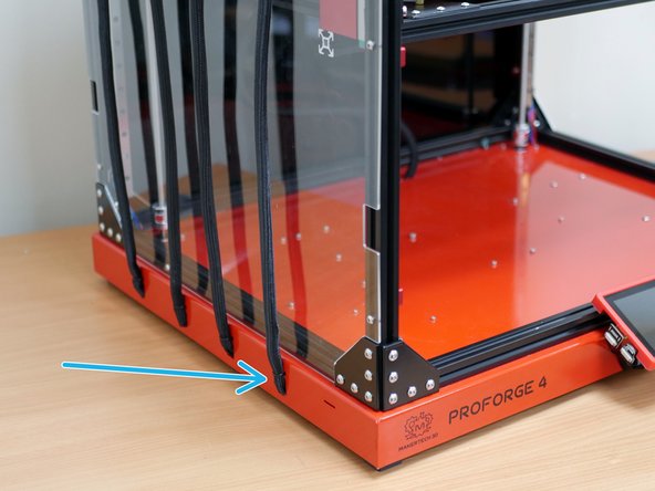
Feed the cable loom into the base and secure with cable ties.
-
-
-
An oversight with the initial batch of kits meant that the bolts which act as spool holders were not included - these have now been shipped separately to everyone.
-


Cancel: I did not complete this guide.
16 other people completed this guide.
