
-
-
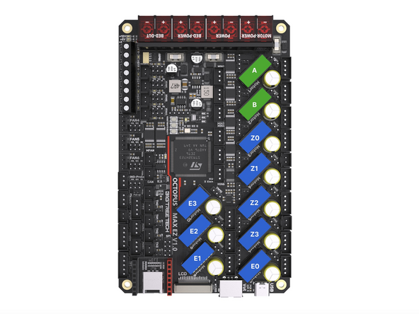
Double check that you have all of the jumpers installed in the positions highlighted in the image and this step here.
-
Powering up with jumpers installed incorrectly can cause irreversible damage to your electronics!
-
Pay special attention to the stepper driver jumpers. These control the voltages going into the driver. Sending 48v to the smaller 24v TMC2209 drivers will cause them to blow.
-
48V Position
-
24V Position
-
For v4.2 these stepper positions are not used as the extruder drivers are on the print heads tool board.
-
-
-
Connect motor cables to the gantry motors as shown.
-
Use the longer twisted cables that are included with the LDO motors.
-
On the rear right corner feed together the static fan, endstop and motor cable.
-
On the front right corner feed the motor cable and camera cable into the base together.
-
The corners on the left side should have just the motor cables going down into them.
-
Tuck the cables into the extrusions and hold in place with the cable tie mounts.
-
Route the cables down into the base.
-
-
-
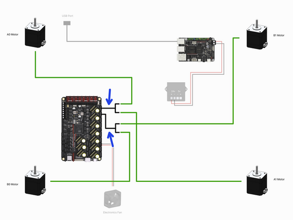
The diagram is orientated relative to the control board and shows the motors in the positions that they would be in if looking up from under the base.
-
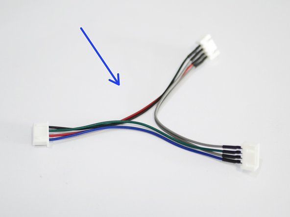
Connect to the control board the two motor cable adapters.
-
Connect to the adapters the four gantry motors as shown in the diagram.
-
-
-
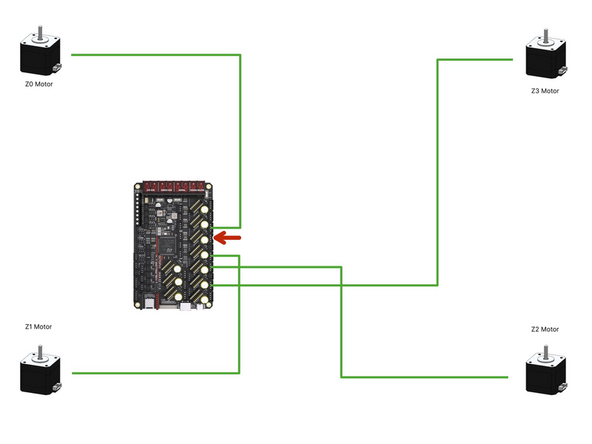
The diagram is orientated relative to the control board and shows the motors in the positions that they would be in if looking up from under the base.
-
Connect the four z-motors to the control board as shown.
-
These are the flat motor cables, not the twisted ones.
-
Note that a connector on the board is skipped out, this is on purpose.
-
-
-
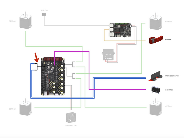
Connect the USB Camera to a free USB port on the BTT Pi board.
-
Connect the X-Endstop to the control board as shown.
-
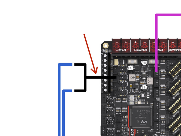
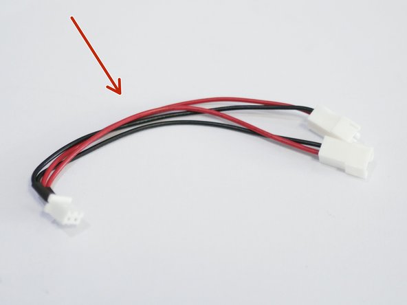
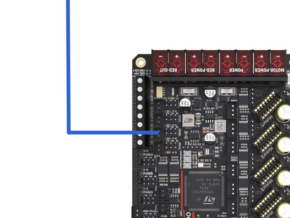
Connect the fan splitter to the control board.
-
Connect to the fan splitter the two static fans.
-
-
-
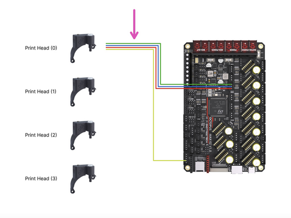
See the next step if you are building v4.2
-
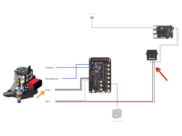
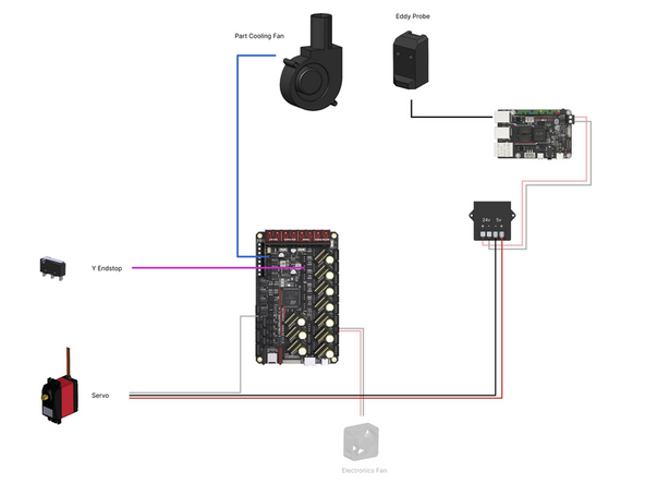
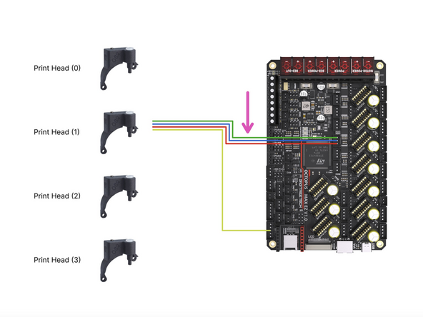
The following cables all come from the tool carriage loom:
-
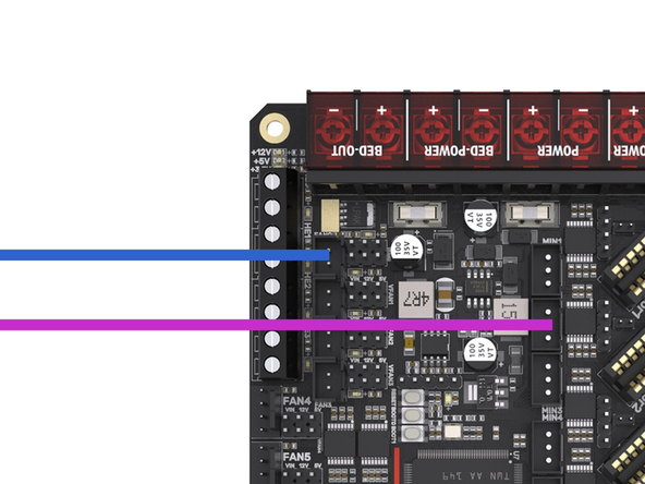
Connect the Y-Endstop to the control board.
-
Connect the part cooling fan to the control board.
-
Connect the bed probe to the control board.
-
Connect the white servo signal cable to the control board as shown.
-
Connect the servos power cables to the 5V output of the convertor. Red to positive and black to negative.
-
-
-
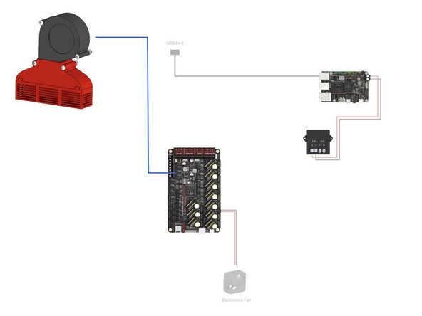
Complete this step if you have the enclosure upgrade installed.
-
Plug the filter fan into the control board as shown.
-
-
-
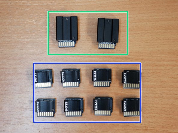
Before unpacking the stepper driver boards make sure that you have grounded yourself. You can do this by touching a large metal object. This is to prevent any static from damaging the drivers when handling them.
-
These drivers can only be plugged in one way. The fin side of the heatsink points to the back of the printer.
-
Plug the TMC5160 RGB EZ Drivers into the board as shown. They will drive the gantry motors.
-
Plug the TMC2209 EZ Drivers into the board as shown. They will drive the Z motors and extruders.
-
If building the 4.2, ignore the E drivers, as these are already on the print head orbiter control boards.
-
-
-
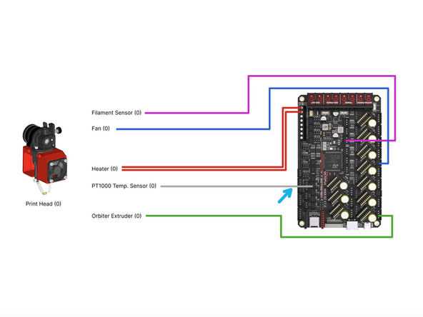
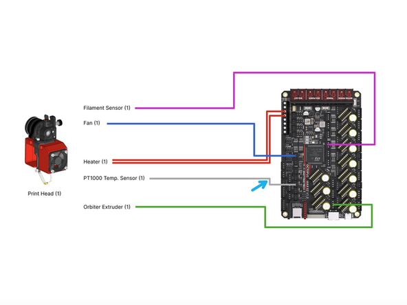
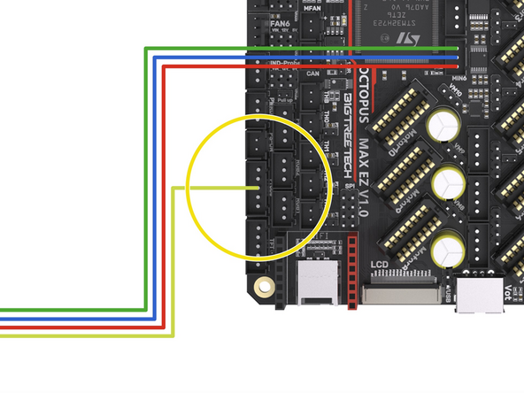
Connect the filament sensor to the control board as shown.
-
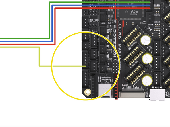
If you are running the Orbiter filament sensor then see the second image for wiring it to the control board.
-
Connect the loose yellow cable from it to the control board as shown. It doesn't have a dedicated position on the control board so we will need to borrow a pin from a header that we are not currently using.
-
We recommend using either tape or a hot glue gun to hold the cable in place.
-
Connect the hotend fan to the position shown on the board.
-
Connect the heater to the HE0 screw terminal on the board.
-
Connect the PT1000 to the TH0 position on the board.
-
Connect the Extruder to the Motor7 position on the board.
-
-
-
Connect the filament sensor to the control board as shown.
-
If you are running the Orbiter filament sensor then see the second image for wiring it to the control board.
-
Connect the loose yellow cable from it to the control board as shown. It doesn't have a dedicated position on the control board so we will need to borrow a pin from a header that we are not currently using.
-
We recommend using either tape or a hot glue gun to hold the cable in place.
-
Connect the hotend fan to the MFAN position on the board.
-
Connect the heater to the HE1 screw terminal on the board.
-
Connect the PT1000 to the TH1 position on the board.
-
Connect the Extruder to the Motor8 position on the board.
-
-
-
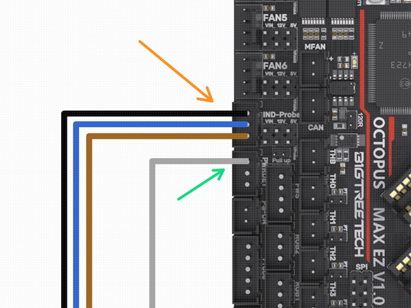
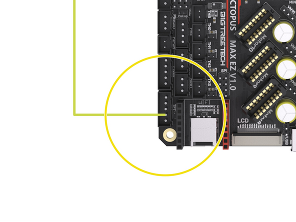
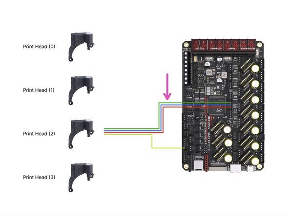
Connect the filament sensor to the control board as shown.
-
If you are running the Orbiter filament sensor then see the second image for wiring it to the control board.
-
Connect the loose yellow cable from it to the control board as shown. It doesn't have a dedicated position on the control board so we will need to borrow a pin from a header that we are not currently using.
-
We recommend using either tape or a hot glue gun to hold the cable in place.
-
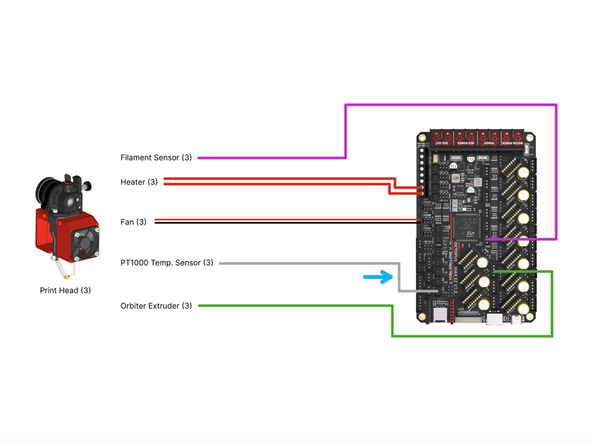
Connect the hotend fan to the FAN6 position on the board - this fan is connected to the two lower pins on the header as shown in the diagram, ensure to orientate the black and red cables as shown.
-
Connect the heater to the HE2 screw terminal on the board.
-
Connect the PT1000 to the TH2 position on the board.
-
Connect the Extruder to the Motor9 position on the board.
-
-
-
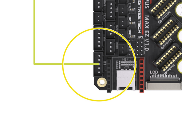
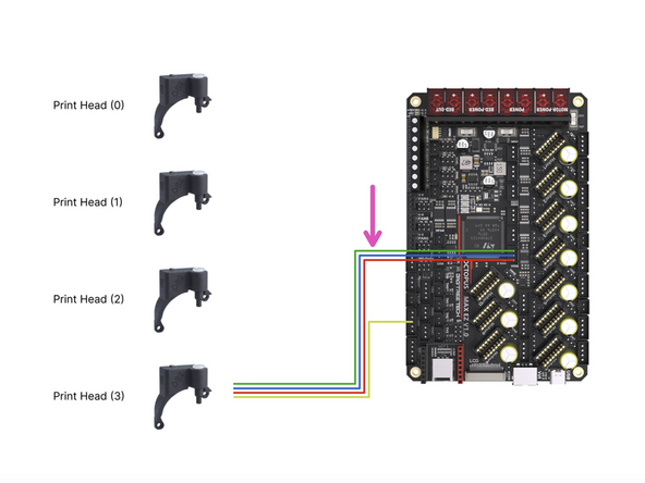
Connect the filament sensor to the control board as shown.
-
If you are running the Orbiter filament sensor then see the second image for wiring it to the control board.
-
Connect the loose yellow cable from it to the control board as shown. It doesn't have a dedicated position on the control board so we will need to borrow a pin from a header that we are not currently using.
-
We recommend using either tape or a hot glue gun to hold the cable in place.
-
Connect the hotend fan to the FAN5 position on the board - this fan is connected to the two lower pins on the header as shown in the diagram, ensure to orientate the black and red cables as shown.
-
Connect the heater to the HE3 screw terminal on the board.
-
Connect the PT1000 to the TH3 position on the board.
-
Connect the Extruder to the Motor10 position on the board.
-


Cancel: I did not complete this guide.
13 other people completed this guide.
